Advertisement
Quick Links
INSTALLATION
INSTRUCTIONS
PARTS LIST
Backup Sensor Attachment Kit
P/N 08V67-STK-200A
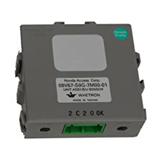
Control unit
Buzzer
Back-up sensor harness
Control unit bracket
Switch
13 Wire ties
2 Short wire ties
(not used)
8 Cushion tapes
© 2011 American Honda Motor Co., Inc. - All Rights Reserved.
Accessory
BACK-UP SENSORS
7 Harness clips
Screw grommet
2 Clips A (with center tab)
2 Clips B (with side tab)
Special screw
Self-tapping screw
Collar
Fuse label
Accessory User's Information Manual
BII 46119 (1108)
Application
2012 RDX
08V67-STK-2000-91
Publications No.
BII 46119
Issue Date
AUG 2011
1 of 12
Advertisement

Related Manuals for Acura 08V67-STK-200A


Summary of Contents for Acura 08V67-STK-200A
- Page 1 2012 RDX Issue Date INSTRUCTIONS AUG 2011 PARTS LIST 7 Harness clips Backup Sensor Attachment Kit P/N 08V67-STK-200A Screw grommet Control unit 2 Clips A (with center tab) Buzzer 2 Clips B (with side tab) Back-up sensor harness Special screw...
- Page 2 Back-up Sensor Kit INSTALLATION Client Information: The information in this installation instruction is intended for use only by skilled technicians who have the proper tools, 2 Corner sensors A equipment, and training to correctly and safely add equipment to your vehicle. These procedures should not be attempted by “do-it-yourselfers.”...
- Page 3 Remove the cargo area lid (four clips). Fold the right rear seat cushion forward, and lay the seat-back flat. 4 CLIPS RIGHT REAR 4 CLIPS SEAT RETAINING CARGO AREA LID TAILGATE OPENING RIGHT REAR 5D26030B SIDE STEP TRIM FRONT 5D26051B Pull up the tailgate weatherstrip in the area shown.
- Page 4 12. Open the right front tie-down hook cover. Remove 14. Remove the bolt cover from the right side trim the front tie-down hook from the right side trim panel, and remove the two bolts and three clips. panel (one screw). RIGHT SIDE BOLTS TRIM PANEL...
- Page 5 17. Remove the right rear speaker (two nuts and three 19. Remove the four caps and four bolts from the rear bolts, and unplug the vehicle connector). bumper. 4 SELF- TAPPING VEHICLE CONNECTOR SCREWS 3 BOLTS 4 CLIPS 4 CAPS REAR 4 BOLTS BUMPER...
- Page 6 24. Install the two corner sensors A and clips A into 22. While wearing eye protection, drill a 3 mm pilot the outer holes and two center sensors B and hole through the outside surface of the rear clips B into the inner holes on the rear bumper. bumper at each of the eight pierced points you just made.
- Page 7 26. Route the four back-up sensor harness 2-pin 28. Route the back-up sensor harness forward and connectors through the vehicle panel. Seat the secure it to the vehicle panel with two cushion back-up sensor harness grommet in the hole. tapes. 27.
- Page 8 30. Route the back-up sensor harness 5-pin (green) 31. Install the screw grommet (supplied) into the connector forward and secure it to the vehicle vehicle panel hole in the area shown. harness with three wire ties. SCREW VEHICLE PANEL VEHICLE GROMMET HOLE CONNECTORS...
- Page 9 35. Route the back-up sensor harness up along the 33. Using isopropyl alcohol, thoroughly clean the vehicle harness, and secure it to the vehicle vehicle panel area where the cushion tape will harness with five wire ties. Don’t secure the back- attach.
- Page 10 38. Plug the back-up sensor harness 2-pin connector 40. Plug the back-up sensor harness 14-pin connector into the vehicle 2-pin connector. into the control unit and install the control unit bracket to the vehicle panel with the special screw. VEHICLE BACK-UP SENSOR VEHICLE BACK-UP...
- Page 11 43. Route the back-up sensor harness 4-pin connector 46. Route the back-up sensor harness along the rear into the 19 mm hole, and reinstall the right quarter bumper beam. pillar trim. 4 HARNESS ADHESIVE BACK-UP CLIPS BACKING SENSOR HARNESS BACK-UP SENSOR REAR BUMPER BACK-UP SENSOR HARNESS 4-PIN...
- Page 12 48. With an assistant holding the rear bumper near the 49. Check that all wire harnesses and cables are vehicle, plug in the four back-up sensor harness routed properly and that all connectors are plugged 2-pin connectors. 50. Reinstall all removed parts. 4 BACK-UP SENSOR 51.
Need help?
Do you have a question about the 08V67-STK-200A and is the answer not in the manual?
Questions and answers