Advertisement
Advertisement
Table of Contents

Related Manuals for DEVI DEVIlink FT


Summary of Contents for DEVI DEVIlink FT
- Page 1 Installation Guide DEVIlink™ FT Floor thermostat www.DEVI.com...
- Page 2 DEVIlink™ FT Table of Contents Introduction � � � � � � � � � � � � � � � � � � � � � 3 Placement of DEVIlink™ FT � � � � � � � � � � � � 4 Operation mode .
-
Page 3: Introduction
DEVIlink™ FT Introduction The DEVIlink™ FT (Floor Thermostat) is a device for switch- ing the heating element ON/OFF. In connection with a floor sensor it can also measure the temperature in the floor (FTS). Secondly you have the possibility to use the FT as a on and off switch to other equipments manually or by schedule. -
Page 4: Placement Of Devilink™ Ft
DEVIlink™ FT Placement of DEVIlink™ FT Installation and placement must be according to local building regulations. 2�1 Operation mode DEVIlink™ FT supports two types of operation modes. 1. Heating regulation 1. On/OFF switching When used in heating regulation mode you have to con- sider the following advices for controlling the heating. - Page 5 DEVIlink™ FTs in a room need to havethe same sensor configuration. DEVI recommends always installing a floor sensor. Do not install floor heating system without a floor sensor when the heating element is installed on or beneath wooden...
-
Page 6: Installation Of Devilink™ Ft
DEVIlink™ FT Installation of DEVIlink™ FT 1. To remove the front cover, gently press the release tabs under the bottom of the thermostat with a screw- driver. Then remove the front. 2. Connect the thermostat according to the connection diagram. LOAD LOAD (Optional) -
Page 7: Technical Specifications
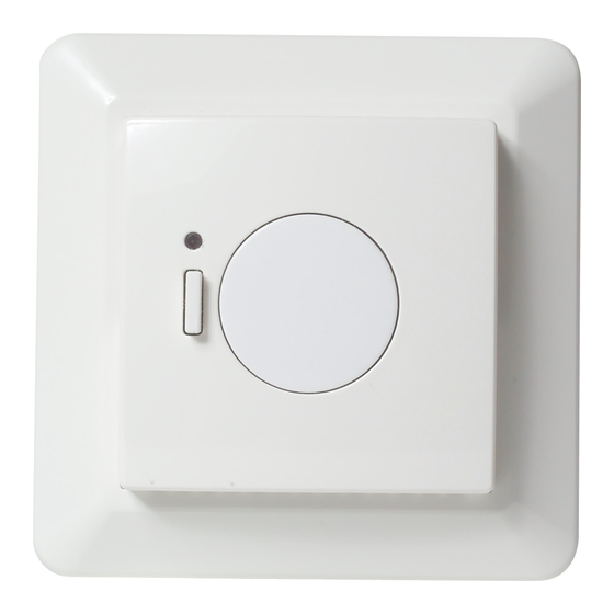
DEVIlink™ FT 3�1 Configuration See Step-by-Step guide in DEVIlink™ CC instruction manual. Green LED ON Standby Red LED ON Heating Green LED fast flash Inclusion or link test Red LED short flash Inclusion not OK, goes to not included. Linktest not OK, goes to missing link RED LED slow flash Sensor failure... - Page 8 DEVIlink™ FT Relay: • Resistive load 230 V ~ 15 A / 3450 W cos ϕ = 0.3 Max. 1 A • Inductive load Sensing unit NTC 15 kOhm at 25°C Sensing values: • 0°C 42 kOhm • 20°C 18 kOhm •...
-
Page 9: Radio Equipment Directive
SIMPLIFIED EU DECLARATION OF CONFORMITY Hereby, Danfoss A/S declares that the radio equipment type DEVIlink™ FT is in compliance with Directive 2014/53/EU The full text of the EU declaration of conformity is available at the following internet address: devi�danfoss�com Warranty Installation Guide... -
Page 10: Disposal Instructions
DEVIlink™ FT Disposal instructions Installation Guide... - Page 11 This also applies to products already on order provided that such alterations can be made without subsequential changes being necessary in specifications already agreed. All trademarks in this material are property of the respective companies. DEVI and the DEVI logo-type are trademarks of Danfoss A/S. All rights reserved Installation Guide 08095924 &...
- Page 12 DEVIlink™ FT Installation Guide...
Need help?
Do you have a question about the DEVIlink FT and is the answer not in the manual?
Questions and answers