Vega VEGABAR 17 Operating Instructions Manual
Process pressure transmitter with metallic measuring cell
Hide thumbs
Also See for VEGABAR 17:
- Operating instructions manual (37 pages) ,
- Operating instructions manual (37 pages) ,
- Operating instructions manual (37 pages)

Related Manuals for Vega VEGABAR 17


Summary of Contents for Vega VEGABAR 17
-
Page 1: Operating Instructions
Operating Instructions Process pressure transmitter with metallic measuring cell VEGABAR 17 Document ID: 27636... -
Page 2: Table Of Contents
Recalibration ........................17 7 Maintenance and fault rectification Maintenance ........................20 Rectify faults ........................20 How to proceed if a repair is needed ................20 Dismount Dismounting steps......................22 Disposal ......................... 22 Supplement Technical data ........................ 23 Dimensions ........................29 VEGABAR 17 •... - Page 3 Contents Safety instructions for Ex areas Take note of the Ex specific safety instructions for Ex applications. These instructions are attached as documents to each instrument with Ex approval and are part of the operating instructions manual. Editing status: 2015-02-10 VEGABAR 17 •...
-
Page 4: About This Document
The dot set in front indicates a list with no implied sequence. → Action This arrow indicates a single action. Sequence of actions Numbers set in front indicate successive steps in a procedure. Battery disposal This symbol indicates special information about the disposal of bat- teries and accumulators. VEGABAR 17 •... -
Page 5: For Your Safety
During work on and with the device the required personal protective equipment must always be worn. Appropriate use VEGABAR 17 is a pressure transmitter for measurement of gauge pressure, absolute pressure and vacuum. You can find detailed information about the area of application in chapter "Product description". Operational reliability is ensured only if the instrument is properly used according to the specifications in the operating instructions manual as well as possible supplementary instructions. -
Page 6: Safety Label On The Instrument
That is why we have introduced an environment management system with the goal of continuously improving company environmental pro- tection. The environment management system is certified according to DIN EN ISO 14001. Please help us fulfill this obligation by observing the environmental instructions in this manual: • Chapter "Packaging, transport and storage" • Chapter "Disposal" VEGABAR 17 •... -
Page 7: Product Description
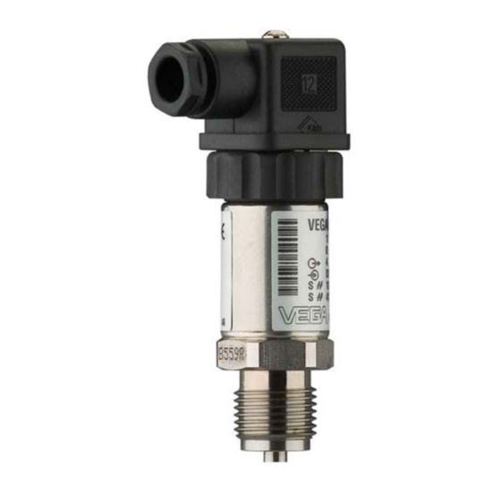
Documentation – this operating instructions manual – Ex-specific "Safety instructions" (with Ex versions) – if necessary, further certificates Configuration Fig. 1: VEGABAR 17 with plug connector according to ISO 4400 1 Process fitting Housing with electronics Pressure compensation (beneath the knurled nut) Plug connector Type label... -
Page 8: Operation
Voltage supply 4 … 20 mA two-wire electronics for voltage supply and measured value transmission on the same cable. Operation The VEGABAR 17 has no adjustment options. However, there are two built-in potentiometers for recalibration of zero and span. Packaging, transport and storage Packaging Your instrument was protected by packaging during transport. Its capacity to handle normal loads during transport is assured by a test based on ISO 4180. -
Page 9: Mounting
Installation procedure For mounting VEGABAR 17, a welded socket is required. You can find Welding the socket these components in the supplementary instructions manual "Welded socket and seals". Sealing/Screwing in Use the seal fitting to the instrument, or in case of NPT connections, a high-resistance sealing material. Screw VEGABAR 17 into the welded socket with a wrench applied to the hexagon of the process fitting. For the proper torque see chapter "Technical data", for spanner size see chapter "Dimensions". VEGABAR 17 •... - Page 10 4 Mounting Fig. 2: Mounting of VEGABAR 17 VEGABAR 17 •...
-
Page 11: Connecting To Power Supply
For the version with round plug connector M12 x 1, a suitable, ready- made connection cable (article no. ASL.1S.) in 5 m, 10 m or 25 m lengths is available from the line of VEGA accessories. If screened cable is required, connect the cable screen on both ends... -
Page 12: Connection Procedure
Proceed as follows: plug connector 1. Loosen the screw on the rear of the plug connector 2. Remove the plug connector and seal from VEGABAR 17 3. Remove the plug insert from the plug housing Fig. 3: Loosen the plug insert... - Page 13 Plug housing Plug insert Plug seal 7. Snap the plug insert into the plug housing and insert the sensor seal 8. Plug the plug insert with seal to VEGABAR 17 and tighten the screw The electrical connection is finished. Connection via angle Proceed as follows: plug connector with 1.
- Page 14 9. Tighten the screws on the strain relief and cable entry 10. Hook in the cover and push onto the plug connection, tighten cover screw 11. Plug the plug insert with seal to VEGABAR 17 and tighten the screw The electrical connection is finished.
-
Page 15: Wiring Plan
Voltage supply and signal output Round plug connector M12 x 1 Fig. 8: Wiring plan, round plug connector M12 x 1, top view to VEGABAR 17 Voltage supply and signal output Connection via connection cable with 4-pole socket M12 x 1... - Page 16 5 Connecting to power supply Terminal housing – – Fig. 10: Wiring plan, terminal housing To power supply or processing system Control instrument (4 … 20 mA measurement) VEGABAR 17 •...
-
Page 17: Setup
6 Setup Setup Setup steps After mounting and electrical connection, VEGABAR 17 is ready for operation. VEGABAR 17 delivers a current of 4 … 20 mA corresponding to the actual process pressure. Further settings are not necessary. Recalibration With both instruments with thread ring or terminal housing, zero and span can be adjusted via integrated potentiometers. Adjustment range: •... - Page 18 4. Set span with exact reference pressure 5. Check zero Fig. 12: Adjustment of zero and span Zero (Z) Span (S) 6. Assemble the instrument and connect it. Instruments with terminal Proceed as follows: housing 1. Screw on the housing cover in connected status VEGABAR 17 •...
- Page 19 6 Setup Fig. 13: Adjustment of zero and span Zero (Z) Span (S) 2. Set zero in unpressurized status, check 4 mA signal in the circuit 3. Set a span with a sufficiently precise reference pressure 4. Check zero 5. Screw the housing lid back on VEGABAR 17 •...
-
Page 20: Maintenance And Fault Rectification
24 hour service hotline Should these measures not be successful, please call in urgent cases the VEGA service hotline under the phone no. +49 1805 858550. The hotline is manned 7 days a week round-the-clock. Since we offer this service worldwide, the support is only available in the English language. The service is free, only standard call charges are incurred. - Page 21 Clean the instrument and pack it damage-proof • Attach the completed form and, if need be, also a safety data sheet outside on the packaging • Please contact the agency serving you to get the address for the return shipment. You can find the agency on our home page www.vega.com. VEGABAR 17 •...
-
Page 22: Dismount
WEEE directive. Correct disposal avoids negative effects on humans and the environ- ment and ensures recycling of useful raw materials. Materials: see chapter "Technical data" If you have no way to dispose of the old instrument properly, please contact us concerning return and disposal. VEGABAR 17 •... -
Page 23: Supplement
Synthetic oil: For measuring ranges up to 16 bar, FDA listed for the food processing industry. For measuring ranges up to 25 bar not available. Halocarbon oil: With version oil and greasefree, not with vacuum measuring ranges, not with absolute measur- ing ranges < 1 bar VEGABAR 17 •... - Page 24 0 … 1 bar/0 … 100 kPa 5 bar/500 kPa 0 … 1.6 bar/0 … 160 kPa 10 bar/1000 kPa 0 … 2.5 bar/0 … 250 kPa 10 bar/1000 kPa 0 … 4 bar/0 … 400 kPa 17 bar/1700 kPa VEGABAR 17 •...
- Page 25 < 0.2 %/10 K Ʋ Meas. ranges 0 … 0.1 and < 0.4 %/10 K 0 … 0.16 bar Relating to the adjusted span, incl. non-linearity, hysteresis and non-reproducibility. Relating to the set span, incl. hysteresis and repeatability. VEGABAR 17 •...
- Page 26 80°C (176°F) 55°C (131°F) 130°C 150°C (266°F) (302°F) Fig. 14: Temperature derating VEGABAR 17 Ambient temperature Process temperature Storage and transport temperature -30 … +100 °C (-22 … +212 °F) Process conditions Product temperature Ʋ Standard -30 … +100 °C (-22 … +212 °F) Under reference conditions, relating to the adjusted span.
- Page 27 ≤ (U - 10 V)/0.02 A- (cable length in m x 0.14 Ω) Ʋ Version with terminal housing ≤ (U -11 V)/0.02 A Ʋ Example - U = 24 V DC (24 V - 10 V)/0.022 A = 636 Ω Electrical protective measures Protection rating Ʋ with angled plug connector IP 65 According to EN 60529/IEC 529. VEGABAR 17 •...
- Page 28 For that reason the associated approval documents of these instruments have to be carefully noted. They are part of the delivery or can be downloaded under www.vega.com via "VEGA Tools" and "Instrument search" as well as via "Downloads" and "Approvals".
-
Page 29: Dimensions
1/4NPT 1/2NPT ø 30 mm (1.18") 84L/84B Fig. 15: VEGABAR 17 standard housing, GBX = G¼ B manometer connection, GDX = G½ B manometer connec- tion, GTX = G½ A according to DIN 3852-E, TBX = G½ B, inside G¼ B, 84L/84B = G1 B front-flush max. 25 bar, 851/85L/85B = G1 B front-flush with O-ring up to 1.6 bar, 861/86L/86B = G½ B front-flush with O-ring > 1.6 bar, NBX = ¼ NPT thread, NDX = ½ NPT thread VEGABAR 17 •... - Page 30 1/4NPT 1/2NPT ø 30 mm (1.18") 84L/84B Fig. 16: VEGABAR 17 standard housing, GBX = G¼ B manometer connection, GDX = G½ B manometer connec- tion, GTX = G½ A according to DIN 3852-E, TBX = G½ B, inside G¼ B, 84L/84B = G1 B front-flush max. 25 bar, 851/85L/85B = G1 B front-flush with O-ring up to 1.6 bar, 861/86L/86B = G½ B front-flush with O-ring > 1.6 bar, NBX = ¼ NPT thread, NDX = ½ NPT thread VEGABAR 17 •...
- Page 31 1/4NPT 1/2NPT ø 30 mm (1.18") 84L/84B Fig. 17: VEGABAR 17 terminal housing, GBX = G¼ B manometer connection, GDX = G½ B manometer connec- tion, GTX = G½ A according to DIN 3852-E, TBX = G½ B, inside G¼ B, 84L/84B = G1 B front-flush max. 25 bar, 851/85L/85B = G1 B front-flush with O-ring up to 1.6 bar, 861/86L/86B = G½ B front-flush with O-ring > 1.6 bar, NBX = ¼ NPT thread, NDX = ½ NPT thread VEGABAR 17 •...
- Page 32 9 Supplement VEGABAR 17 - Cooling elements, plug, cable outlet ~48 mm (1.89") G1/2 Fig. 18: VEGABAR 17 - Cooling elements, plug, cable outlet Cooling element G½ B Cooling element G1 B Plug according to ISO 4400 Cable outlet M12 x 1 plug...
- Page 33 Notes VEGABAR 17 •...
- Page 34 Notes VEGABAR 17 •...
- Page 35 Notes VEGABAR 17 •...
- Page 36 Subject to change without prior notice © VEGA Grieshaber KG, Schiltach/Germany 2015 VEGA Grieshaber KG Phone +49 7836 50-0 Am Hohenstein 113...
Need help?
Do you have a question about the VEGABAR 17 and is the answer not in the manual?
Questions and answers