
Related Manuals for Krautzberger 200-0138


Summary of Contents for Krautzberger 200-0138
- Page 1 Operating instructions Hand-held Spray Gun Mignon 3 T-Dok-198-GB-Rev.3 200-0137 ■ 200-0138 ■ 200-0187 ■ 090-3566 ■ 200-0155 ■ 200-0156 Translation of the original operating instructions...
- Page 2 Thank you for selecting a Krautzberger product. This product has been manufactured following state-of-the-art manufacturing procedures and extensive quality assurance measures. We promise you a product of the highest quality. If you have questions, requests or suggestions, please contact us. We are always glad to assist you.
-
Page 3: Table Of Contents
Temporary shut-down..................... 24 7.5.2 Long-term shut-down....................24 Maintenance........................26 Safety......................... 26 General maintenance information................26 Maintenance schedule....................26 Cleaning the hand-held spray gun................27 Changing the fluid needle..................30 200-0137 ■ 200-0138 ■ 200-0187 ■ 090-3566 ■ 200-0155 ■ 200-0156 GB–3... - Page 4 Spare parts........................52 Accessories........................53 Disassembly and disposal....................54 12.1 Safety........................54 12.2 Disassembly......................54 12.3 Disposal........................54 Technical data........................55 13.1 Dimensions and weight.................... 55 13.2 General specifications..................... 55 13.3 Dimensions......................56 Declaration of conformity....................58 Index..........................59 GB–4 mail@krautzberger.com, www.krautzberger.com...
-
Page 5: Function And Identification
Gravity feed cups and suction cups are made of aluminium, copper or plastic. Before starting up the hand-held spray gun, check the compatibility of the device materials with the coating materials that are used! 200-0137 ■ 200-0138 ■ 200-0187 ■ 090-3566 ■ 200-0155 ■ 200-0156 GB–5... -
Page 6: Identification
Scope of delivery Model Product number Flow design 200-0137 Fluid connection on the handle 200-0138 Fluid connection on the bottom of the head section 200-0187 Compressed air connection from the top on the main body 090-3566 Flow design ; HV3M 200-0155 Fluid connection on the handle ;... -
Page 7: Using This Operating Manual
This combination of symbol and signal word indicates potential dangers to the environment. Tips and recommendations This symbol highlights useful tips and recommendations as well as information for efficient and trouble-free operation. 200-0137 ■ 200-0138 ■ 200-0187 ■ 090-3566 ■ 200-0155 ■ 200-0156 GB–7... -
Page 8: Personnel Requirements
Tasks that go beyond the operation in standard mode must only be carried out by the operator if such is indicated in this manual and the operate has explicitly been tasked to do so. GB–8 mail@krautzberger.com, www.krautzberger.com... -
Page 9: Personal Protective Equipment
The personal protective equipment is described below: Protective work clothing Protective work clothing are tight fitting work clothes with low tear resistance, with tight sleeves, and without any protruding parts. 200-0137 ■ 200-0138 ■ 200-0187 ■ 090-3566 ■ 200-0155 ■ 200-0156 GB–9... - Page 10 Safety goggles are used to protect the eyes from flying parts and splashes of liquid. Protective gloves Protective gloves protect hands from friction, abrasion, puncture wounds, or deeper injuries, as well as from contact with hot surfaces. Safety shoes GB–10 mail@krautzberger.com, www.krautzberger.com...
- Page 11 Safety shoes protect the feet against crushing, falling parts or slipping on slippery ground. Safety helmet The helmet protects the head against injuries from falling parts and oscillating loads as well as in tight spaces. 200-0137 ■ 200-0138 ■ 200-0187 ■ 090-3566 ■ 200-0155 ■ 200-0156 GB–11...
-
Page 12: Safety And Responsibility
Depending on the operating conditions, the sound pressure of the device may cause hearing damage. Take suitable action to reduce the impact of the existing sound pressure level. The owner is responsible for the type and implementation of suitable measures, which may depend on the local conditions. GB–12 mail@krautzberger.com, www.krautzberger.com... -
Page 13: Intended Use
Do not operate the hand-held spray gun in areas that are at risk for explosions. WARNING! Misuse of the hand-held spray gun can cause dangerous situations. No claims of any kind can be asserted due to damage resulting from misuse! 200-0137 ■ 200-0138 ■ 200-0187 ■ 090-3566 ■ 200-0155 ■ 200-0156 GB–13... -
Page 14: Responsibility Of The Owner
Residual risks The hand-held spray gun made by Krautzberger GmbH has been manufactured based on state-of- the-art technology and generally accepted technical safety regulations. Nonetheless, its use can pose a threat to the life or health of users or third parties, damage the hand-held spray gun itself or cause other property damage. -
Page 15: Transport And Storage
The hand-held spray gun is packaged in accordance with the anticipated transport conditions and the packaging needs to protect it against transport damage, corrosion, and other damage. Remove packaging material. Remove potentially present transport safety restraints. 200-0137 ■ 200-0138 ■ 200-0187 ■ 090-3566 ■ 200-0155 ■ 200-0156 GB–15... -
Page 16: Overview
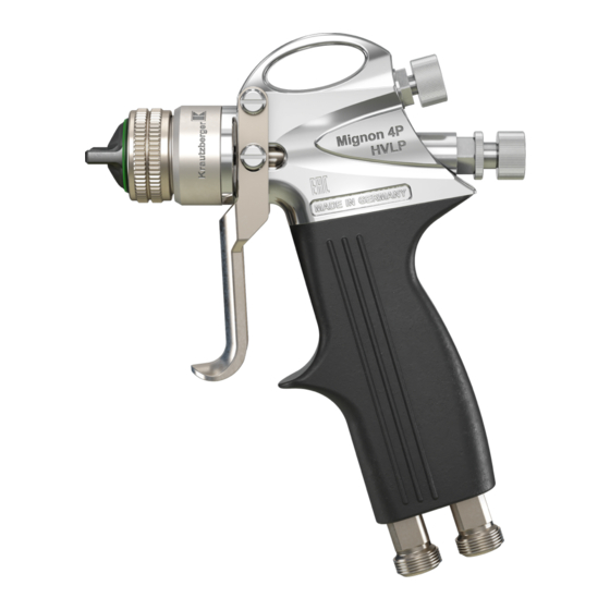
Fluid connection, flow (variant 200-0137 and variant 200-0155) Flat jet controller Needle stroke adjustment screw Main element Compressed-air connection Fluid connection (variant 200-0138 and variant 200-0156) Fluid connection, suction (variant 200-0187) Compressed-air connection (variant 090-3566) 10 Pull lever 11 Air nozzle GB–16... -
Page 17: Installation
Make sure that the connected compressed air is oil-free and free of solid matter. Operate the spray gun with processed, dried compressed air (air quality pursuant to DIN ISO 8573-1: grade 4). Never point the compressed air at living beings. 200-0137 ■ 200-0138 ■ 200-0187 ■ 090-3566 ■ 200-0155 ■ 200-0156 GB–17... -
Page 18: Connections Of The Hand-Held Spray Gun
Depending on the design, connect the compressed-air line to the compressed air connec- tion ( Fig. 2/2 or 5) of the hand-held spray gun. Establish material supply, depending on the design, through gravity feed cup ( Fig. 2/1), suction cup ( Fig. 2/4) or hose ( Fig. 2/3). GB–18 mail@krautzberger.com, www.krautzberger.com... -
Page 19: Operation
Uncontrolled leaks of compressed air can lead to serious injuries. Note: – Prior to any work on the device/machine, all compressed-air lines must be closed and disconnected. – Never point compressed air at living beings. 200-0137 ■ 200-0138 ■ 200-0187 ■ 090-3566 ■ 200-0155 ■ 200-0156 GB–19... -
Page 20: General Information About Start-Up / Commissioning
Do not use sharply abrasive, chemically aggressive, very hot or very cold spray media without first consulting with and receiving approval from Krautzberger GmbH. Adhere to the safety data sheets of the spray media manufacturer. Only operate the hand-held spray gun in compliance with the values specified in ( Ä... -
Page 21: Operation
Nozzle type Description Remark Round jet Cone-shaped stream in front of the nozzle Flat jet Width-adjustable jet for flat-shaped A closed flat jet regulator creates application round jet 200-0137 ■ 200-0138 ■ 200-0187 ■ 090-3566 ■ 200-0155 ■ 200-0156 GB–21... - Page 22 It is recommended that you first adjust the spray pattern by varying the air and coating material pressure. If you cannot achieve satisfactory results this way, you should experiment with other nozzle sizes. GB–22 mail@krautzberger.com, www.krautzberger.com...
- Page 23 Adjust needle stroke with adjustment screw ( Fig. 4/2) on the spray gun. Adjust width of the spray stream with flat jet regulator ( Fig. 4/1). Adjustment only possible for flat jet nozzles. 200-0137 ■ 200-0138 ■ 200-0187 ■ 090-3566 ■ 200-0155 ■ 200-0156 GB–23...
-
Page 24: Shutting Down
Disrupt the spraying process by releasing the pull lever ( Fig. 5/1). Close the material supply and switch off the fluid pressure pump if necessary. Release the residual energy by activating the pull lever ( Fig. 5/1). 7.5.2 Long-term shut-down Fig. 6: Long-term shut-down GB–24 mail@krautzberger.com, www.krautzberger.com... - Page 25 Properly clean the hand-held spray gun before storage and transport so that there is no toxic, flammable or explosive products inside. Clean parts with adhering residual material in an appropriate manner. 200-0137 ■ 200-0138 ■ 200-0187 ■ 090-3566 ■ 200-0155 ■ 200-0156 GB–25...
-
Page 26: Maintenance
The use of incorrect or defective spare parts can cause hazards for the personnel as well as damage, malfunctions or complete failure. – Only use OEM parts from Krautzberger or Krautzberger-approved spare parts. – In case of questions, always contact our Customer Care department. -
Page 27: Cleaning The Hand-Held Spray Gun
Observe the safety data sheets of the medium manufacturer. – Observe the safety data sheets of the cleaning product manufacturer. – Do not use any halogenated cleaning products. 200-0137 ■ 200-0138 ■ 200-0187 ■ 090-3566 ■ 200-0155 ■ 200-0156 GB–27... - Page 28 Depending on the operating conditions, the sound pressure of the hand-held spray gun may cause hearing damage. Start spraying process by activating the pull lever ( Fig. 7/4). Spray until the cleaning product runs clear. End the spraying process by releasing the pull lever ( Fig. 7/4). GB–28 mail@krautzberger.com, www.krautzberger.com...
- Page 29 Never immerse the entire hand-held spray gun in solvent. This could destroy the seals and rinse off the lubricant. Clean the outside of the hand-held spray gun with a cloth soaked in cleaning product. 200-0137 ■ 200-0138 ■ 200-0187 ■ 090-3566 ■ 200-0155 ■ 200-0156 GB–29...
-
Page 30: Changing The Fluid Needle
( Fig. 8/4) on the locking piece ( Fig. 8/3) to the end stop. Unscrew the locking piece ( Fig. 8/3) with a fork wrench. CAUTION! Risk of injury due to fluid needles! Remove the spring ( Fig. 8/2) and the fluid needle ( Fig. 8/1). Fig. 9: Fluid needle GB–30 mail@krautzberger.com, www.krautzberger.com... - Page 31 ENGLISH Hand-held Spray Gun Mignon 3 Loosen the needle pusher ( Fig. 9/2) and unscrew the fluid needle ( Fig. 9/1) from the needle bolt ( Fig. 9/3). 200-0137 ■ 200-0138 ■ 200-0187 ■ 090-3566 ■ 200-0155 ■ 200-0156 GB–31...
- Page 32 Screw fluid needle ( Fig. 10/1) into needle bolt ( Fig. 10/3) and needle pusher ( Fig. 10/2). Fig. 11: Needle dimension Adjust needle dimension ( Fig. 11/I or II) and tighten needle pusher: I: Needle dimension without piercing pin II: Needle dimension with piercing pin lll: Needle dimension valid for variant 200-0187 GB–32 mail@krautzberger.com, www.krautzberger.com...
- Page 33 Screw in locking piece ( Fig. 12/4) and tighten with a fork wrench. Ä Chapter 7.4 Adjust spray pattern with needle stroke adjustment screw ( Fig. 12/5) ( ‘Adjusting the spray pattern’ on page 21). 200-0137 ■ 200-0138 ■ 200-0187 ■ 090-3566 ■ 200-0155 ■ 200-0156 GB–33...
-
Page 34: Changing The Material Nozzle And The Air Nozzle
Activate and hold the pull lever ( Fig. 13/5). Unscrew the fluid nozzle ( Fig. 13/3) with a fork wrench. Always replace fluid nozzle ( Fig. 13/3) and fluid needle ( Fig. 13/4) at the same time. GB–34 mail@krautzberger.com, www.krautzberger.com... - Page 35 Risk of injury through the use of incorrect spare parts! Attach the new air nozzle ( Fig. 14/2) and tighten it with the cap nut ( Fig. 14/1). 200-0137 ■ 200-0138 ■ 200-0187 ■ 090-3566 ■ 200-0155 ■ 200-0156 GB–35...
-
Page 36: Changing The Sealing Cone
Fig. 15: Dismantling the sealing cone Remove the spring ( Fig. 15/4). Pull out sealing bushing ( Fig. 15/3) and sealing cone ( Fig. 15/2) using the dismantling tool. Take out sealing ( Fig. 15/1) and check for wear, replace if necessary. GB–36 mail@krautzberger.com, www.krautzberger.com... - Page 37 Risk of injury through the use of incorrect spare parts! Insert sealing ( Fig. 16/1). Lightly grease the sealing ( Fig. 16/1). We recommend Krautzberger special grease (contact data see last page). Insert the sealing cone ( Fig. 16/2) and the sealing bushing ( Fig. 16/3).
-
Page 38: Changing O-Ring In Air Connection
Interrupt the external material supply. Fig. 17: Removing the O-ring Unscrew double nipple ( Fig. 17/3) of the air connection ( Fig. 17/1) with suitable fork wrench. Remove O-ring ( Fig. 17/2) from the double nipple ( Fig. 17/3). GB–38 mail@krautzberger.com, www.krautzberger.com... - Page 39 Risk of injury through the use of incorrect spare parts! Insert new O-ring ( Fig. 18/2) into the double nipple ( Fig. 18/3). Tighten double nipple ( Fig. 18/3) with a suitable fork wrench. 200-0137 ■ 200-0138 ■ 200-0187 ■ 090-3566 ■ 200-0155 ■ 200-0156 GB–39...
-
Page 40: Changing Needle Pack
34). Fig. 19: Dismantling the needle pack Loosen sealing screw ( Fig. 19/1) with a suitable screw driver. Remove the seal ( Fig. 19/2). Pay attention to position of seal! Remove the needle guide ( Fig. 19/3). GB–40 mail@krautzberger.com, www.krautzberger.com... - Page 41 Tighten sealing screw ( Fig. 20/1) with a suitable screw driver. Ä Chapter 8.6 ‘Changing the material nozzle and the air nozzle’ Attach the fluid nozzle ( on page 34). 200-0137 ■ 200-0138 ■ 200-0187 ■ 090-3566 ■ 200-0155 ■ 200-0156 GB–41...
-
Page 42: Changing O-Ring In The Locking Piece
( Fig. 21/4) on the locking piece ( Fig. 21/3) to the end stop. Unscrew the locking piece ( Fig. 21/3) with a fork wrench. Remove the O-ring ( Fig. 21/2). For that, turn the adjustment screw ( Fig. 21/4) up to the end stop in the locking piece. GB–42 mail@krautzberger.com, www.krautzberger.com... - Page 43 Risk of injury through the use of incorrect spare parts! Insert new O-ring ( Fig. 22/1). Lightly grease the O-ring ( Fig. 22/1). We recommend Krautzberger special grease (contact data see last page). Unscrew adjustment screw ( Fig. 22/3) all the way to the end position.
-
Page 44: Changing O-Ring In The Flat Jet Regulator
If necessary, secure fluid pressure pump or pressurised fluid container for the spray media against restart. Interrupt the external material supply. Fig. 23: Removing the O-ring Dismantle flat jet regulator ( Fig. 23/2) with a suitable fork wrench. Remove the O-ring ( Fig. 23/1). GB–44 mail@krautzberger.com, www.krautzberger.com... -
Page 45: Changing O-Ring In The Fluid Pipe
Risk of injury through the use of incorrect spare parts! Insert new O-ring ( Fig. 24/1). Lightly grease the O-ring ( Fig. 24/1). We recommend Krautzberger special grease (contact data see last page). Tighten flat jet regulator ( Fig. 24/2) with a suitable fork wrench. - Page 46 Fig. 25: Dismantle the handle Loosen double nipple air connection ( Fig. 25/2) with a suitable fork wrench. Pull off handle ( Fig. 25/1). The material connection nipple ( Fig. 25/3) will be pulled off at the same time GB–46 mail@krautzberger.com, www.krautzberger.com...
- Page 47 Pull fluid pipe ( Fig. 26/3) from head piece ( Fig. 26/1) and remove it. Dismantle O-rings ( Fig. 26/2 and 4) from fluid pipe ( Fig. 26/3). 200-0137 ■ 200-0138 ■ 200-0187 ■ 090-3566 ■ 200-0155 ■ 200-0156 GB–47...
- Page 48 Fig. 27: Installing fthe luid pipe WARNING! Risk of injury through the use of incorrect spare parts! Attach new O-rings ( Fig. 27/2 and 4) to fluid pipe. Carefully insert fluid pipe ( Fig. 27/3) in head piece ( Fig. 27/1). GB–48 mail@krautzberger.com, www.krautzberger.com...
- Page 49 Place handle ( Fig. 28/1) and material connection nipple ( Fig. 28/3) onto the fluid pipe. Tighten double nipple air connection ( Fig. 28/2) with a suitable fork wrench. Check O-ring air connection and renew if necessary. 200-0137 ■ 200-0138 ■ 200-0187 ■ 090-3566 ■ 200-0155 ■ 200-0156 GB–49...
-
Page 50: Troubleshooting
Operating instructions T-Dok-198-GB-Rev.3 9 Troubleshooting Personnel: Qualified personnel If the fault is not included in the following tables or if it cannot be eliminated with the measures described, contact Krautzberger Customer Care. Troubleshooting table Spray pattern Error Cause Remedy Normal flat jet spray pattern... -
Page 51: Customer Care
34) fluid nozzle. Customer Care Krautzberger GmbH Customer service Stockbornstr. 13 65343 Eltville am Rhein +49 6123 - 698151 customercare@krautzberger.com 200-0137 ■ 200-0138 ■ 200-0187 ■ 090-3566 ■ 200-0155 ■ 200-0156 GB–51... -
Page 52: Spare Parts
Designation – Item number according to spare parts list – Quantity – Desired shipping method (post, freight, sea, air, express) – Delivery address A complete spare part overview is available on the website of Krautzberger GmbH: www.krautzberger.de GB–52 mail@krautzberger.com, www.krautzberger.com... -
Page 53: Accessories
Hand-held Spray Gun Mignon 3 Accessories A wide range of accessories are available for the spray gun. For further information, visit us on the Internet (www.krautzberger.com) or contact your Krautzberger dealer, consultant or our office staff. Here are a few examples: Gravity feed cup... -
Page 54: Disassembly And Disposal
Sort remaining components based on the respective material and dispose of them accord- ingly. Properly dispose of potential spray fluid residue separately from the device. If in doubt, obtain information about environmentally-appropriate disposal with the local municipali- ties or specialised disposal companies. GB–54 mail@krautzberger.com, www.krautzberger.com... -
Page 55: Technical Data
Sound pressure level (depends on the nozzle) 73-96 dB (A) Vibration < 2.5 Angle of spray jet in front of nozzle up to approx. 90 °C 200-0137 ■ 200-0138 ■ 200-0187 ■ 090-3566 ■ 200-0155 ■ 200-0156 GB–55... -
Page 56: Dimensions
Operating instructions T-Dok-198-GB-Rev.3 13.3 Dimensions Fig. 29: Dimensions variant 200-0137, 200-0155 and variant 200-0138, 200-0156 GB–56 mail@krautzberger.com, www.krautzberger.com... - Page 57 ENGLISH Hand-held Spray Gun Mignon 3 Fig. 30: Dimensions 200-0187 and 090-3566 200-0137 ■ 200-0138 ■ 200-0187 ■ 090-3566 ■ 200-0155 ■ 200-0156 GB–57...
-
Page 58: Declaration Of Conformity
Operating instructions T-Dok-198-GB-Rev.3 Declaration of conformity Fig. 31: Declaration of conformity GB–58 mail@krautzberger.com, www.krautzberger.com... -
Page 59: Index
Weight ............55 200-0137 ■ 200-0138 ■ 200-0187 ■ 090-3566 ■ 200-0155 ■ 200-0156... - Page 61 Krautzberger GmbH Stockbornstrasse 13 65343 Eltville am Rhein, Germany Hotline: +49 (0) 6123 698-222 Reception: +49 (0) 6123 698-0 Fax: +49 (0) 6123 698-200 Email: mail@krautzberger.com Internet: www.krautzberger.com © Krautzberger GmbH 2017 © Krautzberger GmbH 2017...
Need help?
Do you have a question about the 200-0138 and is the answer not in the manual?
Questions and answers