AudioCodes Mediant 4000 SBC Hardware Installation Manual
Audiocodes family of mediant session border controllers (sbc)
Hide thumbs
Also See for Mediant 4000 SBC:
- User manual (1037 pages) ,
- User manual (964 pages) ,
- User manual (930 pages)
Table of Contents
Advertisement
Quick Links
Download this manual
See also:
User Manual
Advertisement
Table of Contents

Related Manuals for AudioCodes Mediant 4000 SBC


Summary of Contents for AudioCodes Mediant 4000 SBC
- Page 1 Hardware Installation Manual AudioCodes Family of Mediant™ Session Border Controllers (SBC) Mediant 4000 SBC...
-
Page 3: Table Of Contents
Hardware Maintenance ..................36 Prerequisites ......................36 6.1.1 Grounding the Device ....................36 6.1.2 Preventing Electrostatic Discharge Damage ............36 Replacing the SBC Module ................... 37 Replacing the Fan Tray and Power Supply Modules ..........39 Session Border Controllers Mediant 4000 SBC... - Page 4 Mediant 4000 SBC List of Figures Figure 3-1: Front Panel .......................... 13 Figure 3-2: SBC Module Ports ....................... 15 Figure 3-3: SBC Module LEDs ......................16 Figure 3-5: Rear Panel........................... 18 Figure 4-1: Rubber Feet Locations ......................20 Figure 4-2: Rear-Mounting Brackets Attached to Rear-Rack Posts (60 cm)......... 23 Figure 4-3: Rear-Mounting Brackets Attached to Rear-Rack Posts (80 cm).........
- Page 5 Please contact your local recycling authority for disposal of this product. Customer Support Customer technical support and services are provided by AudioCodes or by an authorized AudioCodes Service Partner. For more information on how to buy technical support for AudioCodes products and for contact information, please visit our Web site at www.audiocodes.com/support.
- Page 6 Mediant 4000 SBC Related Documentation Manual Name SIP Release Notes Mediant 4000 SBC User's Manual Notes and Warnings Warning: The device is an INDOOR unit and thus, must be installed ONLY indoors. In addition, Ethernet port interface cabling must be routed only indoors and must not exit the building.
- Page 7 Hardware Installation Manual Notices Documentation Feedback AudioCodes continually strives to produce high quality documentation. If you have any comments (suggestions or errors) regarding this document, please fill out the Documentation Feedback form on our Web site at http://www.audiocodes.com/downloads. Session Border Controllers...
- Page 8 Mediant 4000 SBC This page is intentionally left blank. Hardware Installation Manual Document #: LTRT-41511...
-
Page 9: Introduction
Introduction This document provides a hardware description of the Mediant 4000 (hereafter referred to as device) and step-by-step procedures for cabling the device. For configuring the device, refer to the device's User’s Manual. Note: Session Border Controllers Mediant 4000 SBC... - Page 10 Mediant 4000 SBC This page is intentionally left blank. Hardware Installation Manual Document #: LTRT-41511...
-
Page 11: Unpacking The Device
Adjustable Rear-Rack Mounting Bracket Kit for mounting the chassis in a 19-inch rack Two-meter serial interface cable adaptor. Check, retain and process any documents. If there are any damaged or missing items, notify your AudioCodes sales representative. Session Border Controllers Mediant 4000 SBC... - Page 12 Mediant 4000 SBC This page is intentionally left blank. Hardware Installation Manual Document #: LTRT-41511...
-
Page 13: Physical Description
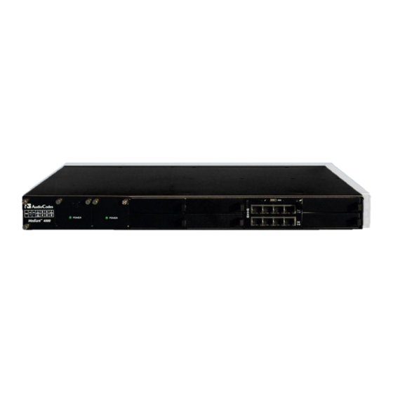
The device's front panel is shown in the figure below and described in the subsequent table. Figure 3-1: Front Panel Note: The figure above provides only an example of the Mediant 4000 hardware configuration; module slot locations and type of modules depend on the ordered hardware configuration. Session Border Controllers Mediant 4000 SBC... -
Page 14: Fan Tray Module
Mediant 4000 SBC Table 3-2: Front-Panel Description Item # Component Description Fan Tray module with a schematic displayed on its front panel showing the chassis' slot numbers. For more information on this module, see Section 3.2.1 on page 14. The figure below shows the location of the Fan Tray module, Power Supply modules, and chassis slot numbers: Power Supply module No. -
Page 15: Sbc Module
Slots 3-4. 3.2.3.1 Ports Description The SBC module provides various port interfaces as shown in the figure below and described in the subsequent table. Figure 3-2: SBC Module Ports Session Border Controllers Mediant 4000 SBC... -
Page 16: Leds Description
Mediant 4000 SBC Table 3-4: SBC Module Ports Description Item # Label Description Reset pinhole button: To reset the device, press the button for at least 1 second but no longer than 10 seconds. To reset the device to factory defaults, press the button for at least 12 seconds but no longer than 25 seconds. - Page 17 Ports established. Blue Blue hot-swap LED indicating that the AMC module can be fully removed or inserted. Note: Do not remove the module before this LED turns blue. The module insertion process is complete. Session Border Controllers Mediant 4000 SBC...
-
Page 18: Rear Panel Description
Mediant 4000 SBC Rear Panel Description The chassis rear panel is displayed in the figure below and described in the subsequent table. Figure 3-4: Rear Panel Table 3-6: Rear-Panel Description Item # Label Description AC power supply inlet (100-240V~2.5A, 50-60 Hz) for Power Supply module No. - Page 19 Hardware Installation Manual 3. Physical Description This page is intentionally left blank. Session Border Controllers Mediant 4000 SBC...
-
Page 20: Mounting The Device
Mediant 4000 SBC Mounting the Device The device can be mounted in one of the following ways: Placed on a desktop - see Section 'Desktop Mounting' on page Installed in a standard, 19-inch rack - see Section ‘Rack Mounting' on page... -
Page 21: 19-Inch Rack Mounting
Reliable Earthing: Reliable earthing of rack-mounted equipment should be maintained. Particular attention should be given to supply connections other than direct connections to the branch circuit (e.g., use of power strips.) Session Border Controllers Mediant 4000 SBC... -
Page 22: Mounting In A 19-Inch Rack Using A Pre-Installed Rack Shelf
Depending on the depth of the rack in which you are installing the device, you can order one of the following rear-mounting brackets, which differ in length, from AudioCodes as a Rear- Rack Mounting Bracket Kit accessory item (separate orderable item): ... -
Page 23: Figure 4-2: Rear-Mounting Brackets Attached To Rear-Rack Posts (60 Cm)
See the figure below for correct orientation of the brackets when attaching them to the posts. Figure 4-2: Rear-Mounting Brackets Attached to Rear-Rack Posts (60 cm) Figure 4-3: Rear-Mounting Brackets Attached to Rear-Rack Posts (80 cm) Session Border Controllers Mediant 4000 SBC... -
Page 24: Figure 4-4: Attaching Rear-Mounting Flange To Chassis' Rear-Side Mounting Holes (60 Cm)
Mediant 4000 SBC Attach the rear-mounting flanges to the rear sides of the chassis, using three screws (supplied) per flange. Figure 4-4: Attaching Rear-Mounting Flange to Chassis' Rear-Side Mounting Holes (60 cm) Figure 4-5: Attaching Rear-Mounting Flange to Chassis' Rear-Side Mounting Holes (80 cm) With two people, lift the chassis into the rack from the front of the rack. -
Page 25: Figure 4-6: Sliding The Rear-Mounting Flanges Into The Rear-Mounting Brackets (60 Cm)
Slide the two rear-mounting flanges into the slide rails of the rear-mounting brackets that you previously attached to the rear posts. Figure 4-6: Sliding the Rear-Mounting Flanges into the Rear-Mounting Brackets (60 cm) Figure 4-7: Sliding the Rear-Mounting Flanges into the Rear-Mounting Brackets (80 cm) Session Border Controllers Mediant 4000 SBC... -
Page 26: Figure 4-8: Fastening Rear-Mounting Flange To Rear-Mounting Bracket (60 Cm)
Mediant 4000 SBC Hold the chassis in position while the second person secures the rear-mounting flanges to the rear-mounting brackets. Insert the supplied screws (6-32 x 5/16 inch) from the inside of the rack, through the flange's grid and into the screw hole on the rear-mounting bracket. -
Page 27: Figure 4-11: Front-Mounting Brackets Flush And Aligned With Front-Rack Posts (80 Cm)
If the depth of the rack exceeds the maximum length of the adjustable rear- mounting brackets, install an additional side rack post to accommodate the length of the rear-mounting bracket. Session Border Controllers Mediant 4000 SBC... -
Page 28: Cabling The Device
Mediant 4000 SBC Cabling the Device This section describes how to cable the device: Grounding the device – see Section on page Connecting to the LAN – see Section on page Connecting to a computer for serial communication – see Section on page ... -
Page 29: Connecting The Ethernet Ports
Connect one end of a straight-through RJ-45 Ethernet Cat 5, 5e, or 6 cable to the Ethernet ports on the LAN module. Figure 5-2: Connecting the LAN Interface Connect the other end of the cable to the LAN network. Session Border Controllers Mediant 4000 SBC... -
Page 30: Deployment Of A Standalone Device
Mediant 4000 SBC 5.2.2 Deployment of a Standalone Device The Ethernet ports on the SBC module can operate in pairs, called Ethernet Groups, to provide Ethernet port 1+1 redundancy. In each pair, one port serves as the active Ethernet port while the other as standby. When the active port fails, the device switches to the standby Ethernet port. -
Page 31: Deployment Of Two Devices For High Availability
In High Availability, the two devices interconnect through their Maintenance interfaces, using the same Ethernet Port Group. Note: For possible connections (including Tx / Rx settings) between the HA devices, refer to the User's Manual. Session Border Controllers Mediant 4000 SBC... -
Page 32: Connecting The Serial Interface To A Computer
Mediant 4000 SBC Connecting the Serial Interface to a Computer The RS-232 interface port is used to access the command line interface (CLI) for serial communication. The cable adapter shown below is provided for this purpose: Figure 5-6: Serial Interface Cable Adapter and Connector Pinouts ... -
Page 33: Connecting To Power
Each module provides an AC power socket on the device's rear panel. If both power modules are used, ensure that you connect each one to a different AC supply socket. The two AC power sources must have the same ground potential. Session Border Controllers Mediant 4000 SBC... -
Page 34: Figure 5-8: Connecting To Power
Mediant 4000 SBC To connect the device to the power supply: Connect the AC power cord (supplied) to one of the power sockets located on the rear panel. Figure 5-8: Connecting to Power Connect the other end of the power cord to a standard AC electrical outlet (100- 240V~50-60 Hz). - Page 35 Hardware Installation Manual 5. Cabling the Device This page is intentionally left blank. Session Border Controllers Mediant 4000 SBC...
-
Page 36: Hardware Maintenance
Mediant 4000 SBC Hardware Maintenance The device is designed as a modular chassis and allows you to order any module as a Field Replacement Unit (FRU). This section describes the procedures for installing or replacing modules. Warning: Maintenance service of this device must be made only by qualified service personnel in restricted access locations and connected to an earthed power socket. -
Page 37: Replacing The Sbc Module
Figure 6-2: Module Handle Partially Pulled Out (Top View) Wait till the Hot Swap Blue LED is lit, which indicates that the shutdown sequence has completed. Grip and pull the module handle firmly to slide the module out of the slot. Session Border Controllers Mediant 4000 SBC... -
Page 38: Figure 6-3: Module Handle Pushed In (Top View)
Mediant 4000 SBC Install the module: Remove the new module from its ESD shielding packet in which it was shipped. Carefully insert the module into the slot and slide it along the slot's guide rails until it makes contact with the card-edge connector located on the backplane. -
Page 39: Replacing The Fan Tray And Power Supply Modules
Using a flathead screwdriver, tighten the two module's mounting pins. Fasten the two screws on the top right-hand corner and the bottom right-hand corner of the front panel of the Fan Tray module. Session Border Controllers Mediant 4000 SBC... - Page 40 International Headquarters Contact us: www.audiocodes.com/info www.audiocodes.com Website: Document #: LTRT-41511...
Need help?
Do you have a question about the Mediant 4000 SBC and is the answer not in the manual?
Questions and answers