
Related Manuals for AudioCodes Mediant 2600 SBC


Summary of Contents for AudioCodes Mediant 2600 SBC
- Page 1 Hardware Installation Manual AudioCodes Family of Mediant™ Session Border Controllers (SBC) Mediant 2600 SBC...
-
Page 3: Table Of Contents
Hardware Installation Manual Contents Table of Contents Introduction ......................9 Unpacking the Device ..................11 Physical Description ..................13 Physical Dimensions ....................13 Front Panel Description ..................13 3.2.1 Fan Tray Module ...................... 14 3.2.2 Power Supply Modules .................... 14 3.2.2.1 Power LED Description ................15 3.2.3... - Page 4 Mediant 2600 E-SBC List of Figures Figure 3-1: Front Panel .......................... 13 Figure 3-2: E-SBC Module Ports ......................15 Figure 3-3: E-SBC Module LEDs ......................16 Figure 3-4: MPM LEDs .......................... 18 Figure 3-5: Rear Panel .......................... 19 Figure 4-1: Rubber Feet Locations ......................21 Figure 4-2: Rear-Mounting Brackets Attached to Rear-Rack Posts (60 cm) .........
- Page 5 Customer Support Customer technical support and services are provided by AudioCodes or by an authorized AudioCodes Service Partner. For more information on how to buy technical support for AudioCodes products and for contact information, please visit our Web site at https://www.audiocodes.com/services-support/maintenance-and-support.
- Page 6 AudioCodes. Avertissement: Cet appareil est destiné à recevoir uniquement des modules AMC approuvés par AudioCodes. Warning: Modules may contain a non-rechargeable lithium battery. If you need to replace the battery, replace it only with batteries of the same type and manufacturer.
- Page 7 Hardware Installation Manual Notices Document Revision Record LTRT Description 41576 Initial versions. 41577 AC power cable warning (Japanese). 41578 Logo updated. 41579 19-inch rack mounting brackets updated. Session Border Controllers Mediant 2600 E-SBC...
- Page 8 Mediant 2600 E-SBC Documentation Feedback AudioCodes continually strives to produce high quality documentation. If you have any comments (suggestions or errors) regarding this document, please fill out the Documentation Feedback form site https://online.audiocodes.com/documentation-feedback. Hardware Installation Manual Document #: LTRT-41579...
-
Page 9: Introduction
Hardware Installation Manual 1. Introduction Introduction This document provides a hardware description of the Mediant 2600 (hereafter referred to as device) and step-by-step procedures for cabling the device. Note: For configuring the device, refer to the device's User’s Manual. Session Border Controllers Mediant 2600 E-SBC... - Page 10 Mediant 2600 E-SBC This page is intentionally left blank. Hardware Installation Manual Document #: LTRT-41579...
-
Page 11: Unpacking The Device
Two AC power cables. • Four anti-slide bumpers for desktop installation. • Two-meter serial interface cable adaptor. Check, retain and process any documents. If there are any damaged or missing items, notify your AudioCodes sales representative. Session Border Controllers Mediant 2600 E-SBC... - Page 12 Mediant 2600 E-SBC This page is intentionally left blank. Hardware Installation Manual Document #: LTRT-41579...
-
Page 13: Physical Description
Hardware Installation Manual 3. Physical Description Physical Description This chapter provides a physical description of the device. Physical Dimensions The device's physical dimensions are listed in the table below. Table 3-1: Physical Dimensions Item Description Enclosure 4/8-slot, 1U chassis Dimensions (H x W x D) 1U x 19”... -
Page 14: Fan Tray Module
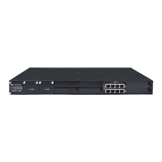
Mediant 2600 E-SBC Item # Component Description Power Supply module No. 2. For more information, see Section 3.2.2 on page Power Supply module No. 1. For more information, see Section 3.2.2 on page Slots 1-2, shown covered with blank AMC modules for unused AMC slots. These slots house the optional, Media Processing Module (MPM). -
Page 15: Power Led Description
Hardware Installation Manual 3. Physical Description 3.2.2.1 Power LED Description Each Power Supply module provides a POWER LED on its front panel which indicates the status of the power supply, as described in the table below. Table 3-3: Power Supply Module LED Description Color State Description... -
Page 16: Leds Description
Mediant 2600 E-SBC Table 3-4: E-SBC Module Ports Description Item # Label Description Reset pinhole button: To reset the device, press the button for at least 1 second but no longer than 10 seconds. To reset the device to factory defaults, press the button for at least 12 seconds but no longer than 25 seconds. - Page 17 Hardware Installation Manual 3. Physical Description Item # Color State Description Active state Yellow Application is starting Boot / synchronizing Flashing Application is running in HA Redundant state Out of service Normal operation Left LED Green Ethernet link established. Flashing Data is being received or transmitted Ethernet (activity) on the Ethernet port.
-
Page 18: Media Processing Module
Mediant 2600 E-SBC 3.2.4 Media Processing Module The Media Processing module (MPM) is an optional, customer-ordered module that provides additional digital signaling resources (DSP) required for transcoding call sessions. The addition of this module increases the maximum number of sessions that can undergo transcoding. -
Page 19: Rear Panel Description
Hardware Installation Manual 3. Physical Description Rear Panel Description The chassis rear panel is displayed in the figure below and described in the subsequent table. Figure 3-5: Rear Panel Table 3-7: Rear-Panel Description Item # Label Description AC power supply inlet (100-240V~2.5A, 50-60 Hz) for Power Supply module No. - Page 20 Mediant 2600 E-SBC This page is intentionally left blank. Hardware Installation Manual Document #: LTRT-41579...
-
Page 21: Mounting The Device
Hardware Installation Manual 4. Mounting the Device Mounting the Device The device can be mounted in one of the following ways: Placed on a desktop (see Section 'Desktop Mounting' on page 21) Installed in a standard 19-inch rack (see Section ‘Rack Mounting' on page 22) Warning: The sides of the chassis, where the air vents are located must remain unobstructed to ensure adequate airflow and prevent overheating inside the chassis. -
Page 22: Rack Mounting
Mediant 2600 E-SBC Rack Mounting The device is designed to fit into a 19-inch industrial rack of 1 rack-unit height (1U). You can mount it in the rack using any one of the following mounting options: (Recommended) Mounting the chassis on a pre-installed shelf in a 19-inch rack – see Section 4.2.1 on page... -
Page 23: Mounting In A 19-Inch Rack Using A Pre-Installed Rack Shelf
Hardware Installation Manual 4. Mounting the Device 4.2.1 Mounting in a 19-inch Rack using a Pre-Installed Rack Shelf The device can be placed on a pre-installed shelf in a 19-inch rack, as described below. This is the recommended method for mounting the device. ... - Page 24 Mediant 2600 E-SBC The device is shipped with the following types of rear-mounting kits, each suited for a specific rack depth: Adjustable rear-mounting bracket whose length can be adjusted from 59.3 to 62.7 cm (23.3 to 24.6 in.) to suit the distance between the chassis and the rear post. Rear-Mounting Bracket x 2 Rear-Mounting Flange x 2 ...
-
Page 25: Figure 4-2: Rear-Mounting Brackets Attached To Rear-Rack Posts (60 Cm)
Hardware Installation Manual 4. Mounting the Device To mount the device in a 19-inch rack using front- and rear-mounting brackets: Open the Rear Mounting Bracket kit and remove its contents. Make sure that all the items are included in the kit (see above). Attach the two rear-mounting brackets to the two-rear rack posts, using two screws (not supplied) per bracket. -
Page 26: Figure 4-4: Attaching Rear-Mounting Flange To Chassis' Rear-Side Mounting Holes (60 Cm)
Mediant 2600 E-SBC Attach the rear-mounting flanges to the rear sides of the chassis, using three screws (supplied) per flange. Figure 4-4: Attaching Rear-Mounting Flange to Chassis' Rear-Side Mounting Holes (60 cm) Figure 4-5: Attaching Rear-Mounting Flange to Chassis' Rear-Side Mounting Holes (> 70 cm) With two people, lift the chassis into the rack from the front of the rack. -
Page 27: Figure 4-6: Sliding Rear-Mounting Flanges Into The Rear-Mounting Brackets (60 Cm)
Hardware Installation Manual 4. Mounting the Device Slide the two rear-mounting flanges into the slide rails of the rear-mounting brackets that you previously attached to the rear posts. Figure 4-6: Sliding Rear-Mounting Flanges into the Rear-Mounting Brackets (60 cm) Figure 4-7: Sliding Rear-Mounting Flanges into the Rear-Mounting Brackets (> 70 cm) Session Border Controllers Mediant 2600 E-SBC... -
Page 28: Figure 4-8: Fastening Rear-Mounting Flange To Rear-Mounting Bracket (60 Cm)
Mediant 2600 E-SBC Hold the chassis in position while the second person secures the rear-mounting flanges to the rear-mounting brackets. Insert the supplied screws (6-32 x 5/16 inch) from the inside of the rack, through the flange's grid and into the screw hole on the rear-mounting bracket. -
Page 29: Figure 4-10: Front-Mounting Brackets Flush And Aligned With Front-Rack Posts (60 Cm)
Hardware Installation Manual 4. Mounting the Device Hold the chassis for support while the second person positions the chassis so that the front-mounting brackets are flush against the front-rack posts and that the holes of the front-mounting brackets align with the holes on the front-rack posts. Figure 4-10: Front-Mounting Brackets Flush and Aligned with Front-Rack Posts (60 cm) Figure 4-11: Front-Mounting Brackets Flush and Aligned with Front-Rack Posts (>... - Page 30 Mediant 2600 E-SBC Tighten the bolts on the front-mounting brackets. With a Philips screwdriver, tighten the screws securing the rear-mounting flanges to the rear-mounting brackets. Notes: • Make sure that all the mounting brackets are attached at the same level to the mounting posts so that the chassis is supported in a horizontal position.
-
Page 31: Cabling The Device
Hardware Installation Manual 5. Cabling the Device Cabling the Device This section describes how to cable the device: Grounding the device – see Section on page Connecting to the LAN – see Section on page Connecting to a computer for serial communication – see Section on page ... -
Page 32: Connecting The Ethernet Ports
Mediant 2600 E-SBC Connecting the Ethernet Ports This section describes the cabling of the LAN interfaces. 5.2.1 RJ-45 LAN Connector Pinouts The RJ-45 connectors with the following pinouts are used for the LAN interfaces: Table 5-1: RJ-45 Connector Pinouts Name Description BI_DA+ Bi-directional pair A+... -
Page 33: Deployment Of A Standalone Device
Hardware Installation Manual 5. Cabling the Device 5.2.2 Deployment of a Standalone Device The Ethernet ports on the E-SBC module can operate in pairs called Ethernet Groups to provide Ethernet port 1+1 redundancy. In each pair, one port serves as the active Ethernet port while the other as standby. -
Page 34: Deployment Of Two Devices For High Availability
Mediant 2600 E-SBC 5.2.3 Deployment of Two Devices for High Availability The device supports 1+1 high availability, whereby two devices are deployed and connected to the same broadcast domain/s. In such a setup, the same Ethernet port-pair redundancy setup is done for each device. For example, if port-pair 5 and 6 are used for Device "A", then Device "B"... -
Page 35: Connecting The Serial Interface To A Computer
Hardware Installation Manual 5. Cabling the Device Connecting the Serial Interface to a Computer The RS-232 interface port is used to access the command line interface (CLI) for serial communication. The cable adapter shown below is provided for this purpose: Figure 5-6: Serial Interface Cable Adapter and Connector Pinouts ... -
Page 36: Connecting To Power
Mediant 2600 E-SBC Connecting to Power The procedure below describes how to connect the device to the power supply. Table 5-2: Power Specifications Item Description Power Supply Up to two hot swappable, power supply modules for power load sharing and AC power redundancy in case of failure of one of the modules. -
Page 37: Figure 5-8: Connecting To Power
Hardware Installation Manual 5. Cabling the Device To connect the device to the power supply: Connect the AC power cord (supplied) to one of the power sockets located on the rear panel. Figure 5-8: Connecting to Power Connect the other end of the power cord to a standard AC electrical outlet (100- 240V~50-60 Hz). - Page 38 Mediant 2600 E-SBC This page is intentionally left blank. Hardware Installation Manual Document #: LTRT-41579...
-
Page 39: Hardware Maintenance
Hardware Installation Manual 6. Hardware Maintenance Hardware Maintenance The device is designed as a modular chassis and allows you to order any module as a Field Replacement Unit (FRU). This section describes the procedures for installing or replacing modules. Warning: Maintenance service of this device must be made only by qualified service personnel in restricted access locations and connected to an earthed power socket. -
Page 40: Replacing The E-Sbc Module
Mediant 2600 E-SBC To attach an ESD wrist strap to the chassis: Attach the ESD wrist strap to your body (typically, the wrist) so that it is in direct contact with your skin. Attach the other end of the wrist strap (e.g., an alligator clip) to the ESD spring screw located on the rear panel of the chassis, as shown below. -
Page 41: Installing The Mpm
Hardware Installation Manual 6. Hardware Maintenance Install the module: Remove the new module from its ESD shielding packet in which it was shipped. Carefully insert the module into the slot and slide it along the slot's guide rails until it makes contact with the card-edge connector located on the backplane. Using only the module handle, press the module into the chassis to engage it with the chassis backplane. -
Page 42: Replacing The Fan Tray And Power Supply Modules
Mediant 2600 E-SBC Push the module handle of the MPM until it clicks firmly in to engage the MPM with the chassis backplane. Note: If you purchased this device in an initial release where the E-SBC module is housed in Slots 3-4, you must relocate this module to Slots 5-6 instead, as shown below: Follow the instructions in Section for replacing this module. - Page 43 Hardware Installation Manual 6. Hardware Maintenance To replace the Fan Tray or Power Supply modules: Remove the module: Using a flathead screwdriver, on the front panel of the module, loosen the two screws securing the module to the chassis. Grip the two screws and gently slide the module out of the chassis slot.
- Page 44 Website: ©2018 AudioCodes Ltd. All rights reserved. AudioCodes, AC, HD VoIP, HD VoIP Sounds Better, IPmedia, Mediant, MediaPack, What’s Inside Matters, OSN, SmartTAP, User Management Pack, VMAS, VoIPerfect, VoIPerfectHD, Your Gateway To VoIP, 3GX, VocaNom, AudioCodes One Voice and CloudBond are trademarks or registered trademarks of AudioCodes Limited.
Need help?
Do you have a question about the Mediant 2600 SBC and is the answer not in the manual?
Questions and answers