Raritan PX3TS User Manual
Transfer switch
Hide thumbs
Also See for PX3TS:
- User manual (842 pages) ,
- Quick setup manual (11 pages) ,
- User manual (696 pages)
Table of Contents
Advertisement
Quick Links
Download this manual
See also:
User Manual
Advertisement
Table of Contents

Related Manuals for Raritan PX3TS


Summary of Contents for Raritan PX3TS
- Page 1 PX3TS Transfer Switch User Guide Release 3.2.10 Copyright © 2016 Raritan, Inc. PX3TS-0F-v3.2.10-E March 2016 255-80-0033-00...
-
Page 2: Safety Guidelines
60950-1 or equivalent rating. Attempting to power non-rated devices may result in electric shock, fire, personal injury and death. WARNING! Do not use a Raritan product containing outlet relays to power large inductive loads such as motors or compressors. Attempting to power a large inductive load may result in damage to the relay. -
Page 3: Safety Instructions
Safety Instructions 1. Installation of this product should only be performed by a person who has knowledge and experience with electric power. 2. Make sure the line cord is disconnected from power before physically mounting or moving the location of this product. 3. - Page 4 Raritan, Inc. © Copyright 2016 Raritan, Inc. All third-party software and hardware mentioned in this document are registered trademarks or trademarks of and are the property of their respective holders.
-
Page 6: Table Of Contents
Contents Safety Guidelines Safety Instructions What's New in the PX3TS User Guide xvii Chapter 1 Introduction Product Models ..........................1 PX3TS Overview..........................2 Front View..........................2 Rear View ..........................3 Package Contents.......................... 4 APIPA and Link-Local Addressing....................4 Chapter 2 Installation and Configuration Before You Begin........................... - Page 7 Mixing Diverse Sensor Types....................41 Before Connecting Equipment to Feature Port................46 Connecting Asset Management Sensors ..................46 Combining Regular Asset Sensors..................47 Connecting Regular Asset Sensors to the PX3TS ............49 Connecting Blade Extension Strips ...................51 Connecting Composite Asset Sensors (AMS-Mx-Z) ............54 Connecting a Logitech Webcam....................56 Connecting a GSM Modem ......................57...
- Page 8 Replacing a Fuse on 2U Models ..................94 Overcurrent Protectors for Outlets....................95 Resetting the Button-Type Circuit Breaker................95 Beeper ............................96 Power Cycling the PX3TS ......................96 Chapter 5 Using the Web Interface Supported Web Browsers......................98 Logging in to the Web Interface....................98 Login ..........................
- Page 9 Resetting Inlet Active Energy Readings ................209 Outlet Management ........................209 Naming Outlets ........................209 Viewing Outlet Information ....................210 Outlet Switching.......................213 PX3TS Latching Relay Behavior ..................216 Setting the Default Outlet State ..................217 Changing the Cycling Power-Off Period................219 Setting the Initialization Delay ..................221 Setting the Inrush Guard Delay ..................222 Setting the Outlet Power-On Sequence ................222...
- Page 10 Expanding a Blade Extension Strip .................320 Displaying the Asset Sensor Information ................321 Bulk Configuration........................322 Saving the PX3TS Configuration..................323 Copying the PX3TS Configuration...................324 Backup and Restore of PX3TS Device Settings................325 Webcam Management.......................326 Configuring Webcams .....................326 Adjusting Image Properties .....................327 Viewing Webcam Snapshots or Videos ................328 Sending Snapshots or Videos in an Email or Instant Message ........330...
- Page 11 Monitoring the LHX/SHX ....................340 Turning the LHX/SHX On or Off ..................343 Requesting Maximum Cooling for an SHX-30..............344 Firmware Upgrade ........................344 Updating the PX3TS Firmware..................345 Viewing Firmware Update History ...................347 Full Disaster Recovery ....................347 Updating the Asset Sensor Firmware................348 Accessing the Help ........................348 Retrieving Software Packages Information ..............348...
- Page 12 Clearing Information........................397 Clearing Event Log ......................397 Clearing WLAN Log......................398 Entering Configuration Mode .....................398 Quitting Configuration Mode ......................399 PX3TS Control and Configuration .....................399 Controlling the Transfer Switch ..................399 PDU Configuration Commands ..................404 Network Configuration Commands..................412 Time Configuration Commands..................436 Checking the Accessibility of NTP Servers ..............440 Security Configuration Commands..................441...
- Page 13 Switching On an Actuator ....................522 Switching Off an Actuator ....................522 Example - Turning On a Specific Actuator ..............523 Unblocking a User........................523 Resetting the PX3TS .........................523 Restarting the PDU......................524 Resetting Active Energy Readings ..................524 Resetting to Factory Defaults ..................525 Network Troubleshooting......................525 Entering Diagnostic Mode ....................525...
- Page 14 Step A. Determine User Accounts and Roles................580 Step B. Configure User Groups on the AD Server ..............581 Step C. Configure LDAP Authentication on the PX3TS Device ..........582 Step D. Configure Roles on the PX3TS Device ................584 Appendix H Updating the LDAP Schema Returning User Group Information.....................588...
- Page 15 Sensor Threshold Settings ......................626 Thresholds and Sensor States ..................627 "To Assert" and Assertion Timeout..................629 "To De-assert" and Deassertion Hysteresis ..............631 PDView App for Viewing the PX3TS ..................633 Altitude Correction Factors ......................635 Ways to Probe Existing User Profiles ..................636 Raritan Training Website ......................636 Appendix K Integration Dominion KX II / III Configuration ....................637...
- Page 16 What's New in the PX3TS User Guide The following sections have changed or information has been added to the PX3TS User Guide based on enhancements and changes to the equipment and/or user documentation. (on page 4) APIPA and Link-Local Addressing...
- Page 17 Chapter 1: What's New in the PX3TS User Guide (on page 336) Downloading Diagnostic Information (on page 398) Clearing WLAN Log (on page Enabling or Disabling Peripheral Device Auto Management 411) (on page 432) Determining the SSH Authentication Method (on page 439)
-
Page 18: Chapter 1 Introduction
APIPA and Link-Local Addressing ............4 Product Models The PX3TS comes in several models that are built to stock and can be obtained almost immediately. Raritan also offers custom models that are built to order and can only be obtained on request. -
Page 19: Px3Ts Overview
This section introduces the components shown on the front and rear panels of a PX3TS device. Front View All components on the front panel are the same on all PX3TS models except that those models rated over 20A (North America) or 16A (international) contain overcurrent protectors for controlling the current flowing through outlets. -
Page 20: Rear View
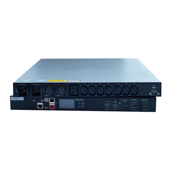
Chapter 1: Introduction USB-A port FEATURE port 2. LCD display and control buttons 3. Transfer switch status indicators, including: Power quality indicator lamps Inlet configuration indicator lamps Active inlet indicator lamps 4. Transfer switch alarm indicators 5. -
Page 21: Package Contents
APIPA and the link-local address is replaced by the DHCP-assigned address. Scenarios where APIPA applies: DHCP is enabled on the PX3TS, but no IP address is assigned to the PX3TS. This may be caused by the absence or malfunction of DHCP servers in the network. - Page 22 Chapter 1: Introduction Note: Configuration by connecting the PX3TS to a computer using a network cable is an application of this scenario. See Connecting the PX3TS to a Computer (on page 12). The PX3TS previously obtained an IP address from the DHCP server, but the lease of this IP address has expired, and the lease cannot be renewed, or no new IP address can be obtained.
-
Page 23: Chapter 2 Installation And Configuration
Raritan's Technical Support Department for assistance. 4. Verify that all circuit breakers on the PX3TS device are set to ON. If not, turn them ON. Or make sure that all fuses are inserted and seated properly. If there are any fuse covers, ensure that they are closed. -
Page 24: Checking The Branch Circuit Rating
Mounting a PX3TS Device Using appropriate brackets and tools, fasten the 1U or 2U PX3TS device to the rack or cabinet. The way to install a PX3TS device varies according to the device length. To mount a PX3TS device which is long: 1. - Page 25 Chapter 2: Installation and Configuration 2. Adjust slide-rail assemblies to match your rack posts and fasten them to the rack using your own fasteners. 3. Line up the mounting brackets with slide-rails and push this product into rails.
- Page 26 4. Fasten front mounting ears to the rack using your own fasteners. To mount a PX3TS device which is short: 1. Attach a rackmount bracket to both sides of the PX3TS with the provided screws. For a 1U model, the total number and locations of screw holes are different from the following 2U diagram.
-
Page 27: Inlet And Outlet Power Connections
The PX3TS connects to two different, but identically rated, branch circuits. The PX3TS will operate when the branch circuit voltages are out of phase, but works most reliably and fastest when in phase. The front panel Phase Sync lamp lights if inlets are out of phase. -
Page 28: Connecting Power And Equipment
Your PX3TS may have fuses and/or circuit breakers. Verify that all are firmly seated or set to ON before connecting power. The PX3TS inlets are labeled INLET 1 (I1) and INLET 2 (I2). INLET 1 is the factory default preferred inlet, and INLET 2 is the factory default alternate inlet. -
Page 29: Connecting The Px3Ts To A Computer
Chapter 2: Installation and Configuration Connecting the PX3TS to a Computer The PX3TS can be connected to a computer for configuration via one of the following ports. ETHERNET port (female) USB-B port (male) RS-232 serial port (male) -
Page 30: Installing The Usb-To-Serial Driver (Optional)
Automatic driver installation is highly recommended. ® Automatic driver installation in Windows 1. Make sure the PX3TS is NOT connected to the computer via a USB cable. 2. Run dominion-serial-setup-<n>.exe on the computer and follow online instructions to install the driver. - Page 31 Chapter 2: Installation and Configuration 3. Connect the PX3TS to the computer via a USB cable. The driver is automatically installed. ® Manual driver installation in Windows 1. Make sure the PX3TS has been connected to the computer via a USB cable.
-
Page 32: Connecting The Px3Ts To Your Network
Connecting the PX3TS to Your Network To remotely administer the PX3TS, you must connect the PX3TS to your local area network (LAN). The PX3TS can be connected to a wired or wireless network. Note: If your PX3TS will be used as a master device in the USB-cascading configuration where the bridging mode applies, make a wired connection. - Page 33 Supported Wireless LAN Configuration If wireless networking is preferred, ensure that the wireless LAN configuration of your PX3TS matches the access point. The following is the wireless LAN configuration that the PX3TS supports. Network type: 802.11 A/B/G/N ...
-
Page 34: Initial Network Configuration Via Cli
3. In the communications program, press Enter to send a carriage return to the PX3TS. 4. The PX3TS prompts you to log in. Both user name and password are case sensitive. a. Username: admin b. Password: raritan (or a new password if you have changed it). - Page 35 Chapter 2: Installation and Configuration where <mode> is wired (default) or wireless. b. For the wired network mode, you may configure the LAN interface settings. In most scenarios, the default setting (auto) works well and should not be changed unless required. To set Use this command LAN interface...
- Page 36 Chapter 2: Installation and Configuration To set Use this command EAP outer network wireless authentication eapOuterAuthentication <outer_auth> <outer_auth> = PEAP EAP inner network wireless authentication eapInnerAuthentication <inner_auth> <inner_auth> = MSCHAPv2 EAP identity network wireless eapIdentity <identity> <identity> = your user name for EAP authentication EAP passord network wireless eapPassword...
- Page 37 Chapter 2: Installation and Configuration Whether to Use this command Make the network wireless connection allowConnectionWithIncorrectC successful by lock <option3> ignoring the "incorrect" system time <option3> = true or false d. To determine which IP protocol (IPv4 or IPv6) is enabled and which IP address (IPv4 or IPv6) returned by the DNS server is used, configure the following parameters.
- Page 38 Chapter 2: Installation and Configuration To set Use this command Preferred host network <version> name preferredHostName <name> (optional) <name> = preferred host name Tip: To override the DHCP-assigned DNS servers with those you specify manually, type this command: network <version> overrideDNS <option> where <option>...
-
Page 39: Bulk Configuration Methods
Tip: You can type "show network wireless" to display a shortened version of wireless settings. 11. If all are correct, type exit to log out of the PX3TS. If any are incorrect, repeat Steps 7 to 10 to change network settings. -
Page 40: Cascading The Px3Ts Via Usb
539). Cascading the PX3TS via USB You can use USB cables to cascade up to eight Raritan devices. All devices in the USB-cascading chain share the Ethernet connectivity. Different Raritan models can be cascaded as long as they are running an appropriate firmware. - Page 41 Wireless LAN Adapters 4. Connect the USB-A port of the master device to the USB-B port of an additional PX3TS via a USB cable. This additional device is Slave 5. Connect Slave 1's USB-A port to the USB-B port of an additional PX3TS via a USB cable.
- Page 42 Chapter 2: Installation and Configuration Number Device role Master device Slave 1 Slave 2 Slave 3...
- Page 43 Identifying Cascaded Devices (on page 128). Tip: The USB-cascading configuration can be a combination of diverse Raritan products that support the USB-cascading feature, including PX2, PX3, PX3TS, EMX and BCM. See the USB-Cascading Solution Guide on Raritan website's Support page (http://www.raritan.com/support/).
-
Page 44: Chapter 3 Connecting External Equipment (Optional)
An environmental sensor package may comprise sensors only or a combination of sensors and actuators. The PX3TS can manage a maximum of 32 sensors and/or actuators. The supported maximum cabling distance is 98 feet (30 m), except for DPX sensor packages. -
Page 45: Dpx Sensor Packages
Connect the adapter's RJ-45 connector to the RJ-45 SENSOR port of the PX3TS. To directly connect a differential air pressure sensor: 1. Connect a Raritan-provided phone cable to the IN port of a differential air pressure sensor. 2. Get an RJ-12 to RJ-45 adapter. Connect the adapter's RJ-12 connector to the other end of the phone cable. - Page 46 Using an Optional DPX-ENVHUB4 Sensor Hub Optionally, you can connect a Raritan DPX-ENVHUB4 sensor hub to the PX3TS. This allows you to connect up to four DPX sensor packages to the PX3TS via the hub. The DPX-ENVHUB4 sensor hub supports DPX sensor packages only.
- Page 47 DPX-ENVHUB4 sensor hub DPX sensor packages Using an Optional DPX-ENVHUB2 cable A Raritan DPX-ENVHUB2 cable doubles the number of connected environmental sensors per SENSOR port. This cable supports DPX sensor packages only. Do NOT connect DPX2, DPX3 or DX sensor packages to it.
- Page 48 Chapter 3: Connecting External Equipment (Optional) 2. The cable has two RJ-12 sensor ports. Connect DPX sensor packages to the cable's sensor ports. 3. Repeat the above steps if there are additional SENSOR ports on your PX3TS.
- Page 49 PX3TS and the sensor hub is up to 33' (10 m). Maximum Distance Illustration: The following illustrates the maximum distance when connecting DPX sensor packages with a maximum 16' (5 m) sensor cable to a PX3TS via a sensor hub. ...
-
Page 50: Dpx2 Sensor Packages
RJ-12 connector and one to three head connectors. You have to connect DPX2 sensor packages to the sensor cable. For more information on DPX2 sensor packages, access the Environmental Sensors Guide or Online Help on Raritan website's (http://www.raritan.com/support/). Support page Item... - Page 51 NOT work properly. Therefore, always occupy all head connectors prior to the final sensor package with a DPX2 sensor package. To connect DPX2 sensor packages to the PX3TS: 1. Connect a DPX2 sensor package to the first head connector of the DPX2 sensor cable.
-
Page 52: Dpx3 Sensor Packages
DPX3 sensor package. LED for indicating the sensor status. To connect DPX3 sensor packages to the PX3TS: 1. Connect a standard network patch cable (CAT5e or higher) to either RJ-45 port on the DPX3 sensor package. - Page 53 Chapter 3: Connecting External Equipment (Optional) Repeat the same steps to cascade more DPX3 sensor packages. 3. Connect the first DPX3 sensor package to the PX3TS by plugging its cable's connector into the RJ-45 SENSOR port of the PX3TS. Connecting a DPX2 Sensor Package to DPX3 You can connect only one DPX2 sensor package to the "end"...
-
Page 54: Dx Sensor Packages
PX3TS. For example, if you cascade 12 DX packages, and each package contains 3 functions (a function is a sensor or actuator), the PX3TS does NOT manage the last 4 functions because the total 36 (12*3=36) exceeds 32 by 4. - Page 55 Exception: You CANNOT cascade DX-PD2C5 sensor packages. A PX3TS device supports only one DX-PD2C5. 3. Connect the first DX sensor package to the PX3TS by plugging its cable's connector into the RJ-45 SENSOR port of the PX3TS. 4. If needed, connect a DPX2 sensor package to the end of the DX chain.
- Page 56 Chapter 3: Connecting External Equipment (Optional) Connecting a DPX2 Sensor Package to DX You can connect only one DPX2 sensor package to the "end" of a DX sensor chain. It is strongly recommended to use an RJ-12 to RJ-45 adapter for connecting the DPX2 to the final DX in the chain. The maximum number of DX sensor packages in the chain must be less than 12 when a DPX2 sensor package is involved.
-
Page 57: Using An Optional Dpx3-Envhub4 Sensor Hub
Plug the other end of the cable into the RJ-45 SENSOR port of the PX3TS. 2. Connect the Raritan sensor packages to any of the four OUT ports on the hub. An RJ-12 to RJ-45 adapter is required for connecting a DPX or ... -
Page 58: Mixing Diverse Sensor Types
DPX3-ENVHUB4 sensor hub is required. The PX3TS does NOT support any other sensor-mixing combinations than those described in this section. When mixing different sensor types, remember that the PX3TS supports a maximum of 32 sensors/actuators. 1 DX + 1 DPX: ... - Page 59 Chapter 3: Connecting External Equipment (Optional) A DPX2 sensor package A DPX sensor package...
- Page 60 Chapter 3: Connecting External Equipment (Optional) An RJ-12 to RJ-45 adapter is recommended to connect a DPX or DPX2 sensor package to DPX3-ENVHUB4. In the following diagrams, the sensor package in "green" can be replaced by a DPX2 sensor package. The sensor package in "blue" can be one DPX2, DPX3 or DX sensor package.
- Page 61 Chapter 3: Connecting External Equipment (Optional)
- Page 62 Chapter 3: Connecting External Equipment (Optional) Mix DPX3 and DX in a sensor chain: Any DX sensor package in a chain can be replaced by a DPX3 sensor package. For example, the following diagram shows a sensor chain comprising both DX and DPX3 sensor packages. The total number of sensor packages in this chain cannot exceed 12.
-
Page 63: Before Connecting Equipment To Feature Port
ID and positioning information to the PX3TS. Raritan asset tags: An asset tag is adhered to an IT device. The asset tag uses an electronic ID to identify and locate the IT device. Warning: The PX3TS does NOT support simultaneous connection of both DX-PD2C5 and asset management sensor(s) so do NOT connect both of them to the PX3TS device. -
Page 64: Combining Regular Asset Sensors
The difference between the master and slave asset sensors is that the master asset sensor has an RJ-45 connector while the slave does not. The following diagram illustrates some asset sensors. Note that Raritan provides more types of asset sensors than the diagram. - Page 65 Chapter 3: Connecting External Equipment (Optional) Make sure that the U-shaped sheet metal adjacent to the male DIN connector is inserted into the rear slot of the master asset sensor. Screw up the U-shaped sheet metal to reinforce the connection.
-
Page 66: Connecting Regular Asset Sensors To The Px3Ts
IT device at one end and plugged in to an asset sensor at the other. The asset sensor is connected to the PX3TS, and the asset tag transmits the ID and positioning information to the asset sensor. - Page 67 The PX3TS device Asset sensors Asset tags IT devices, such as servers Note: The PX3TS cannot detect how many rack units the connected asset sensor(s) has. You must provide the information to it manually. Configuring the Asset Sensor (on page 317).
-
Page 68: Connecting Blade Extension Strips
For blade servers, which are contained in a single chassis, you can use a blade extension strip to track individual blade servers. Raritan's blade extension strip functions similar to a Raritan asset sensor but requires a tag connector cable for connecting it to a tag port on the regular or composite asset sensor. - Page 69 Cable socket(s) for connecting the tag connector cable Note: Each tag port on the blade extension strip is labeled a number, which is displayed as the slot number in the PX3TS device's web interface. To install a blade extension strip: 1.
- Page 70 Up to 128 asset tags on blade extension strips are supported per FEATURE port. Note: If you need to temporarily disconnect the blade extension strip from the asset sensor, wait at least 1 second before re-connecting it back, or the PX3TS device may not detect it.
-
Page 71: Connecting Composite Asset Sensors (Ams-Mx-Z)
Tag ports To connect composite asset sensors to the PX3TS device: 1. Connect a composite asset sensor to the PX3TS device via a standard network patch cable (CAT5e or higher). a. Connect one end of the cable to the RJ-45 port labeled "Input"... - Page 72 The maximum cable length between composite asset sensors is 2 meters, but the total cable length cannot exceed 10 meters. The maximum number of composite asset sensors that can be daisy chained vary according to the Raritan device.
-
Page 73: Connecting A Logitech Webcam
Important: Do NOT mix different types of composite asset sensors in a chain. For example, all in the chain are AMS-M2-Z or all are AMS-M3-Z. Connecting a Logitech Webcam Connect webcams to PX3TS in order to view videos or snapshots of the webcam's surrounding area. The following UVC-compliant webcams are supported: ... -
Page 74: Connecting A Gsm Modem
Important: If a USB hub is used to connect the webcam, make sure it is a "powered" hub. Snapshots or videos captured by the webcam are immediately displayed in the PX3TS web interface after the connection is complete. See (on page 328). Viewing Webcam Snapshots or Videos... -
Page 75: Connecting An Analog Modem
This dial-in feature provides an additional alternative to access the PX3TS when the LAN access is not available. To dial in to the PX3TS, the remote computer must have a modem connected and dial the correct phone number. -
Page 76: Connecting A Schroff Lhx/Shx Heat Exchanger
To remotely monitor and administer the Schroff LHX-20, LHX-40 and ® SHX-30 heat exchangers through the PX3TS device, you must establish a connection between the heat exchanger and the PX3TS device. For more information on the LHX/SHX heat exchanger, see the user documentation accompanying that product. -
Page 77: Chapter 4 Using The Px3Ts
Power Cycling the PX3TS ...............96 Power Transfer The PX3TS has two inlets: INLET 1 and INLET 2. These inlets are to connect to diverse power sources. One inlet is configured as the primary (preferred), and the other is configured as the standby (alternate). The factory default preferred power source is Inlet 1, and the default alternate source is Inlet 2. -
Page 78: Automatic Transfer
The preferred inlet's power quality (voltage or frequency) enters the critical level. Power quality is indicated through the Power Quality indicator lamps. (on page 68). Power Quality Indicator Lamps The table below indicates which inlet the PX3TS selects when the power quality changes. Inlet power quality Active inlet Preferred... - Page 79 Chapter 4: Using the PX3TS Automatic Transfer Scenarios The PX3TS determines whether an automatic power transfer from the preferred to the alternate inlet should be performed based on the status or fault occurred on both inlets. The following table indicates when an automatic transfer is allowed to occur.
-
Page 80: Automatic Retransfer
An internal hardware malfunction on the preferred inlet's circuitry may lead to a less reliable power state. Note: The PX3TS indicates an alarm through the Alarm indicator lamps. Alarm Indicator Lamps (on page 70). Tip: Per default the automatic retransfer can be performed only when both inlets are in phase. - Page 81 Chapter 4: Using the PX3TS Tip: To remotely perform manual transfer using the web interface, see Remote Manual Transfer (on page 125). To transfer using the CLI, see Performing Manual Transfer (on page 399). A manual transfer using the front panel button is prevented if: ...
- Page 82 Fuse alarm 12V SMPS fault Whenever the PX3TS prevents a manual transfer from being performed, it is disabled across all interfaces, including the front panel button, web interface and CLI command. Note: Switch open/short, MOV, 12V SMPS faults are internal transfer switch faults, causing the Internal Failure indicator lamp on the front panel to turn on.
-
Page 83: Transfer Switch Indicator Lamps
Manual transfer is prevented when the PX3TS enters an alarm state, such as the Phase Sync alarm. In certain scenarios, you still can force the PX3TS to perform a manual transfer by holding the Alarm Override button while pressing the Manual Transfer button. See Manual Transfer (on page 65). - Page 84 Chapter 4: Using the PX3TS These lamps are divided into 3 sections to indicate the inlet power status or configuration. Section Lamp type Function Power Inlet power quality is shown using a tricolor LED. Quality For details, see Power Quality Indicator Lamps (on page 68).
-
Page 85: Power Quality Indicator Lamps
Chapter 4: Using the PX3TS Power Quality Indicator Lamps The PX3TS monitors AC voltage and frequency of both inlets and rates the power quality into 3 categories. When the power quality of any inlet changes, the corresponding Power Quality lamp, which is a tricolor LED, changes its colors. -
Page 86: Inlet Configuration Indicator Lamps
A green LED indicates which inlet is preferred. The default is Inlet 1. A "Preferred" inlet is the power source that you prefer using for powering the PX3TS as long as this inlet's power is available and power quality is good. The other inlet is the "Alternate" inlet. -
Page 87: Alarm Indicator Lamps
Chapter 4: Using the PX3TS Alarm Indicator Lamps The PX3TS provides five Alarm indicator lamps, which are lit to alert you when the PX3TS detects unusual or abnormal transfer switch conditions. Indicator lamps Meaning when the lamp is on Manual Disabled The front panel Manual Transfer button is disabled. -
Page 88: Control Push Buttons
(on page 73). Short Circuit Detection Control Push Buttons The PX3TS provides three buttons on the front panel to perform manual transfer or verify the transfer switch indicator lamps. The table describes each button's function. Button... -
Page 89: Testing Indicator Lamps
Chapter 4: Using the PX3TS Button Description Lamp Test Turns on all transfer switch indicator lamps. Power Quality LEDs turn orange. (on page 72). Testing Indicator Lamps Manual Transfer Transfers power to the other inlet. Newly-activated inlet becomes the preferred inlet. -
Page 90: Short Circuit Detection
A short circuit in the load results in a power failure on the active inlet. The PX3TS monitors load current and does NOT perform an automatic power transfer if power fails because of an overload. Instead, the PX3TS activates the Overload alarm and turns on the Overload lamp. See (on page 70). -
Page 91: Connection Port Functions
LEDs show a steady color and the front panel display illuminates. Connection Port Functions A PX3TS model has 8 connection ports on the front and back panels respectively. Front panel CONSOLE port is functionally identical to back panel CONSOLE port, and front panel USB-A port is functionally identical to back panel USB-A port. - Page 92 Establishing a serial connection between the PX3TS and a computer or MODEM modem. This is a standard DTE RS-232 port. You can use a null-modem cable with two DB9 connectors on both ends to connect the PX3TS to the computer. SENSOR Connection to one of the following devices: (RJ-45) ...
-
Page 93: Lcd Display
(on page 23). LCD Display A PX3TS series model uses an LCD display to show the device's data. The following diagram shows the LCD display panel on a 1U model. The LCD display can show the reading or status of different components on the PX3TS, or this device's MAC address and IP address. -
Page 94: Overview Of The Character Lcd Display
Two types of information may be displayed: The "ALARM" status of the selected target. The selected inlet line number if your PX3TS is a 3-phase model. The measurement unit of the displayed data, such as % This section indicates: ... -
Page 95: Control Buttons
Chapter 4: Using the PX3TS Control Buttons There are four control buttons. Up and Down buttons for selecting a specific target, which can be an inlet, overcurrent protector, environmental sensor or a device setting MODE button for switching between various modes, including... - Page 96 2. On a multi-inlet model, press the Up or Down button until the desired inlet's number is displayed at the top. 3. If your PX3TS is a 3-phase model, the selected inlet line is indicated below the reading. Press the Up or Down button until the desired inlet line's number (L1, L2, L3, L1-L2, L2-L3 or L3-L1) is shown.
- Page 97 The outlet mode is NOT available for PX3TS-1000 series. The Outlet mode is displayed as "OUTLET" on the LCD display. By default the PX3TS displays the current reading of OUTLET 1. Below illustrates the outlet information shown on the LCD display.
- Page 98 This circuit breaker's current reading is 0 amps. The word "CLOSE" indicates that the state of the selected circuit breaker is closed. The word "MASTER" indicates the PX3TS is the master device in a USB-cascading configuration. See (on page 23).
- Page 99 IP address octets. It will cycle through four octets. "i4" indicates that the IP address shown on the LCD display is an IPv4 address. The word "MASTER" indicates the PX3TS is the master device in a USB-cascading configuration. See (on page 23).
- Page 100 Chapter 4: Using the PX3TS If you connect your PX3TS to the wireless network, a Wi-Fi icon is displayed at the bottom-right corner. To display the IPv4 address: 1. Press the MODE button to enter the Device mode, indicated by an alphabet "d"...
- Page 101 Chapter 4: Using the PX3TS Section Example information The word "MASTER" indicates the PX3TS is the master device in a USB-cascading configuration. See (on page 23). Cascading the PX3TS via USB Note: For a standalone PX3TS, this word is NOT displayed.
- Page 102 The selected target is the environmental sensor whose ID number is 9 (SENSOR 9). The selected environmental sensor's reading is 22 The word "MASTER" indicates the PX3TS is the master device in a USB-cascading configuration. See Cascading (on page 23).
- Page 103 Chapter 4: Using the PX3TS States Description The sensor enters the alarmed state. This state is accompanied with the word "ALARM" below it. Available states for a dry contact signal actuator (DX sensor series): States Description The actuator is turned on.
- Page 104 Chapter 4: Using the PX3TS 7. Press the FUNC button to display the serial number of the sensor, which is shown as "s:XX," where XX are two digits of the serial number. The LCD will cycle through the serial number from the first two digits to the final two.
- Page 105 Chapter 4: Using the PX3TS To cancel the outlet switching operation, press the FUNC button again. 4. To turn on the outlet, press the Up button. The "on?" confirmation message displays. To turn off the outlet, press the Down button. The "oF?" confirmation message displays.
- Page 106 Chapter 4: Using the PX3TS Asset Sensor Information If there is any asset sensor connected to the PX3TS, you can enter the Asset Sensor mode to show the asset tag state of each rack unit on the asset sensor. For the Raritan asset sensor, a rack unit refers to a tag port.
- Page 107 "CA" indicates that the USB-cascading information is being displayed. "SLAVE" indicates that this PX3TS is a slave device. Note: For a master device, it shows the word "MASTER" instead. The number 1 means the device position is Slave 1.
-
Page 108: Reset Buttons
Slave 6 Slave 7 Note 1: For a standalone PX3TS, its position is the number 0, but the word "MASTER" is NOT shown on the LCD display. Note 2: If reversing or disconnecting the USB cable from a slave device, causing the slave device to become a master or standalone device, you must plug an Ethernet cable to it to update its USB-cascading status. -
Page 109: Fuses For The Inlet Transfer Switch
Fuses for the Inlet Transfer Switch PX3TS models always contain two fuses for protecting the inlet transfer switch. These fuses blow when the current flowing through them exceeds the fuse rating. -
Page 110: Replacing A Fuse On 1U Models
Checking Inlet Component (on page 119). Status 2. Examine your PX3TS and the connected equipment to remove or resolve the cause that results in the overload or short circuit. This step is required, or you cannot proceed with the next step. -
Page 111: Replacing A Fuse On 2U Models
6. Insert a new fuse into the holder. Make sure the new fuse's rating is identical to the original one's. 7. Install back the fuse holder to the PX3TS and turn it clockwise until it is tightened properly. Replacing a Fuse on 2U Models This section introduces how to replace a fuse on a 2U model. -
Page 112: Overcurrent Protectors For Outlets
1. Locate the breaker whose ON button is up, indicating that the breaker has tripped. 2. Examine your PX3TS and the connected equipment to remove or resolve the cause that results in the overload or short circuit. This step is required, or you cannot proceed with the next step. -
Page 113: Beeper
The beeper stops after all tripped overcurrent protectors have been reset, or all blown or bad fuses are replaced with good ones. Warning: You must power OFF the PX3TS prior to replacing a fuse, or a personal injury or death may be caused. -
Page 114: Chapter 5 Using The Web Interface
Viewing Connected Users ..............293 Monitoring Server Accessibility..............294 Environmental Sensors and Actuators ..........299 Asset Management................317 Bulk Configuration .................322 Backup and Restore of PX3TS Device Settings ........325 Webcam Management ................326 Network Diagnostics................335 Downloading Diagnostic Information.............336 Managing the Schroff LHX/SHX Heat Exchanger.........337 Firmware Upgrade.................344... -
Page 115: Supported Web Browsers
To log in to the web interface, you must enter a user name and password. The first time you log in to the PX3TS, use the default user name (admin) and password (raritan). For details, see the Quick Setup Guide accompanying the product. - Page 116 4. If a security agreement is displayed on the Login page, accept it. Otherwise, you cannot log in successfully. To select the agreement checkbox using the keyboard, press the Space bar. 5. Click Login or press Enter. The PX3TS page opens.
- Page 117 Chapter 5: Using the Web Interface Depending on your hardware configuration, elements shown on the web interface may appear slightly different from this image.
- Page 118 Chapter 5: Using the Web Interface Note: The IP address to access a slave device in the USB-cascading configuration where the port forwarding mode is applied is a combination of the IP address and the port number. See Port Forwarding Examples (on page 160).
-
Page 119: Changing Your Password
Internet Explorer or Firefox. The PX3TS does NOT support other browser password managers. Logout After finishing your tasks with the PX3TS, you should log out to prevent others from accessing the web interface. To log out of the web interface: 1. -
Page 120: Introduction To The Web Interface
Chapter 5: Using the Web Interface Close the web browser by clicking the Close button ( ) on the top-right corner of the browser. Close the web browser by choosing File > Close, or File > Exit. The command varies according to the version of the browser you use. -
Page 121: Menus
Help displays firmware and open source information, and a link to the online help. PX Explorer Pane The hierarchical tree to the left displays the PX3TS device you are accessing as well as all physical components embedded on or connected to this product, such as inlets, outlets, and environmental sensors. - Page 122 (on page 108). Expanding the Tree The icons representing all components implemented on or connected to the PX3TS device are expanded by default. If they are hidden, you may expand the tree manually to show all component icons. To expand the tree: 1.
- Page 123 Chapter 5: Using the Web Interface If it is not expanded, click the white arrow prior to the folder icon, or double-click the folder. The arrow then turns into a black, gradient arrow , and icons of components or component groups appear below the PDU folder.
-
Page 124: Setup Button
Status Bar The status bar shows five pieces of information. 1. Device name: This is the name assigned to the PX3TS device. The default is "my PX." See (on page 132). Naming the PDU 2. -
Page 125: Add Page Icon
Chapter 5: Using the Web Interface Tip: The presence of the device name and IP address in the status bar indicates the connection to the PX3TS device. If the connection is lost, it shows " " instead. 3. Login name: This is the user name you used to log in to the web interface. -
Page 126: Data Pane
Chapter 5: Using the Web Interface The following diagram shows a multi-tab example. 4. With multiple pages opened, you can take these actions: To switch to one of the opened data pages, click the corresponding tab. If there are too many tabs to be all shown, two arrows ( ) appear at the left and right borders of the pane. - Page 127 Chapter 5: Using the Web Interface The Yellow- or Red-Highlighted Sensors When a numeric sensor's reading enters the warning or critical range, the background color of the sensor row turns to yellow or red for alerting you. For a discrete (on/off) sensor, the row changes the background color when the sensor enters the abnormal state.
- Page 128 Chapter 5: Using the Web Interface To find the exact meaning of the alert, read the information shown in the State (or Status) column: below lower critical: The numeric sensor's reading drops below the lower critical threshold. below lower warning: The numeric sensor's reading drops below the lower warning threshold.
- Page 129 Browser-Defined Shortcut Menu A shortcut menu, which is built in the web browser, may appear when right-clicking anywhere in the PX3TS web interface. The shortcut menu functions are defined by the browser. For example, the Back command on the Internet Explorer (IE) shortcut menu works ®...
-
Page 130: Viewing The Dashboard
Viewing the Dashboard When you log in to the web interface, the Dashboard page is displayed by default. This page provides an overview of the PX3TS device's status. The page is divided into various sections according to the component type, such as inlet and overcurrent protectors. -
Page 131: Transfer Switch
Chapter 5: Using the Web Interface Transfer Switch The Transfer Switch section of the Dashboard page shows the transfer switch status. A normal state's text color is black while a critical state's is red. Status Description Operational State There are four states: normal, standby, non-redundant and off. -
Page 132: Alerted Sensors
Chapter 5: Using the Web Interface Alerted Sensors One of the sections on the Dashboard page only displays critical or warning conditions detected by internal or external sensors so that you are alerted to take actions. This section is labeled Alerted Sensors. The Alerted Sensors section lists any or all of the following: Any sensor that enters the warning or critical range if the ... -
Page 133: Transfer Switch Management
Chapter 5: Using the Web Interface Column Description Reason The first event that triggers the alert. First Appearance The date and time when the event indicated in the Reason column occurred for the first time. Last Appearance The date and time when the event indicated in the Reason column occurred for the last time. - Page 134 Chapter 5: Using the Web Interface 4. To manually perform power transfer, click Manual Transfer. See (on page 125). Remote Manual Transfer To view the states of different transfer switch components: a. To check the transfer switch status, locate the section labeled Status. (on page 114) for each field's information.
- Page 135 Chapter 5: Using the Web Interface e. To view the waveform of final power transfer, go to the section labeled "Waveform of last transfer." See Last Power Transfer's (on page 126). Waveform...
-
Page 136: Checking Inlet Component Status
Indicates whether each fuse works properly. open: The fuse works fine. closed: The fuse is blown or malfunctions. unavailable: The PX3TS cannot determine the fuse's status. For example, "unavailable" is shown when there is no inlet power... -
Page 137: Configuring Power Transfer Settings
Tip: To check the status of an overcurrent protector for outlets, such as a circuit breaker, see Monitoring Overcurrent Protectors (on page 229). Configuring Power Transfer Settings The following lists the factory default transfer settings of the PX3TS: The front panel Manual Transfer button is enabled. Automatic retransfer is enabled. - Page 138 Chapter 5: Using the Web Interface 4. Determine whether automatic retransfer can be performed when inlets are out of phase. Deselect this checkbox if inlet phase synchronization is not required. 5. (Optional) Thresholds for inlet phase angle difference reporting. Values do not affect phase sync detection or transfers. To configure the thresholds of inlet phase angle difference: 1.
-
Page 139: Configuring Power Quality Settings
If either is warning, quality is warning. When both are normal, power quality is normal. PX3TS transfers to standby operation when preferred inlet power quality goes critical and retransfers to normal operation when power quality returns to normal. - Page 140 Chapter 5: Using the Web Interface Open the Transfer Switch TS1 page and click Power Quality Setup to configure power quality thresholds. The numbers in the above diagram match the following numbers. Voltage and frequency configuration is identical. 1. Enter upper and lower thresholds for Warning and Critical power quality states.
-
Page 141: Viewing The Transfer Log
Chapter 5: Using the Web Interface Viewing the Transfer Log The Transfer Log displays all transfer switch-related events. To open the Transfer Log: 1. Click Transfer Switch TS1 to open its page. 2. Click Transfer Log. 3. The dialog shows the final page by default. You can: ... -
Page 142: Remote Manual Transfer
When manual transfer is prevented, an error message similar to the following appears. Note: Whenever the PX3TS prevents a manual transfer from being performed, it is disabled across all interfaces, including the front panel button, web interface and CLI command. -
Page 143: Last Power Transfer's Waveform
Last Power Transfer's Waveform The waveform of the power transfer for the last time is retained in the PX3TS web interface until another power transfer occurs. Click the Transfer Switch TS1 folder in the navigation tree to open the Transfer Switch TS1 page. -
Page 144: Device Management
Chapter 5: Using the Web Interface Device Management Using the web interface, you can retrieve basic hardware and software information, give the PX3TS a new device name, set the system date and time, and modify network settings that were entered during the initial configuration process. - Page 145 Tip: The firmware version is also available by clicking the PDU folder in the PX Explorer pane. Identifying Cascaded Devices This section explains how to identify a cascaded PX3TS in the Device Information dialog. For information on how to cascade devices using USB cables, see (on page 23).
- Page 146 Chapter 5: Using the Web Interface Fields Description Networking Mode Indicates how the PX3TS is connected to the LAN. Wired: The device is connected to the LAN through a standard network cable. Wireless: The device is connected to the LAN through a supported USB wireless LAN adapter.
- Page 147 Chapter 5: Using the Web Interface A master device shows 0 (zero) in the Cascade Position field and yes in the Cascaded Device Connected field. A slave device in the middle position shows a non-zero number which indicates its exact position in the Cascade Position field and yes in the Cascaded Device Connected field.
- Page 148 Chapter 5: Using the Web Interface The following diagram shows 1, indicating it is the first slave - Slave 1. The final slave device shows a non-zero number which indicates its position in the Cascade Position field and no in the Cascaded Device Connected field.
-
Page 149: Naming The Pdu
Slave 2. The Cascaded Device Connected field shows no, indicating that it is the final one in the chain. Naming the PDU The default name for PX3TS root folder is my PX. You may give it a unique device name. To change the device name: 1. - Page 150 Auto: The PX3TS selects the optimum transmission mode through auto-negotiation. Full: Data is transmitted in both directions simultaneously. Half: Data is transmitted in one direction (to or from the PX3TS device) at a time. 6. Click OK. Tip: You can check the LAN status in the Current State field, including...
- Page 151 3. In the Network Interface field, click the drop-down arrow, and select Wireless from the list. 4. Check the Hardware State field to ensure that the PX3TS device has detected a wireless USB LAN adapter. If not, verify whether the USB LAN adapter is firmly connected or whether it is supported.
- Page 152 Select the "Enable Verification of TLS Certificate Chain" checkbox for the PX3TS to verify the validity of the TLS certificate that will be installed. For example, the PX3TS will check the certificate's validity period against the system time.
- Page 153 11). If necessary, you can modify any network settings later. Selecting the Internet Protocol The PX3TS device supports two types of Internet protocols -- IPv4 and IPv6. You can enable either or both protocols. After enabling the desired Internet protocol(s), all but not limited to the following protocols will be compliant with the enabled Internet protocol(s): ...
- Page 154 If your local network contains two subnets and IP forwarding has been enabled, you can click Append to add static routes so that your PX3TS can communicate with the other subnet. Each static route requires: Destination: IP address of the other subnet and subnet...
- Page 155 (on page 140) for illustrations. Static Route Examples 4. Click OK. Note: The PX3TS supports a maximum of 3 DNS servers. If two IPv4 DNS servers and two IPv6 DNS servers are available, the PX3TS only uses the primary IPv4 and IPv6 DNS servers.
- Page 156 Static Route Examples illustrations. 4. Click OK. Note: The PX3TS supports a maximum of 3 DNS servers. If two IPv4 DNS servers and two IPv6 DNS servers are available, the PX3TS only uses the primary IPv4 and IPv6 DNS servers.
- Page 157 (NIC) have been installed in one network server, leading to two available subnets, and IP forwarding has been enabled. All of the NICs and PX3TS devices in the examples use static IP addresses.
- Page 158 Chapter 5: Using the Web Interface In this example, NIC-2 (192.168.100.88) is the next hop router for your PX3TS to communicate with any device in the other subnet 192.168.200.0. In the IPv4 "Append new Route" dialog, you should specify: ...
-
Page 159: Modifying Network Service Settings
As Internet communications are carried out on the basis of IP addresses, appropriate DNS server settings are required for mapping domain names (host names) to corresponding IP addresses, or the PX3TS may fail to connect to the given host. Therefore, DNS server settings are important for external authentication. - Page 160 Chapter 5: Using the Web Interface HTTPS uses Transport Layer Security (TLS) technology to encrypt all traffic to and from the PX3TS device so it is a more secure protocol than HTTP. By default, any access to the PX3TS device via HTTP is automatically redirected to HTTPS.
- Page 161 Chapter 5: Using the Web Interface 4. To select a different authentication method, select one of the checkboxes. Password authentication only: Enables the password-based login only. Public key authentication only: Enables the public key-based login only. Password and public key authentication: Enables both the password- and public key-based login.
- Page 162 The SNMP v1/v2c read-only access is enabled by default. 3. Enter the MIB-II system group information, if applicable. Important: You must download the SNMP MIB for your PX3TS to use with your SNMP manager. Click Download MIB in this dialog to download the desired MIB file.
- Page 163 Modifying an Action (on page 290). Changing Modbus/TCP Settings You can enable or disable the Modbus/TCP access to the PX3TS or the read-only mode, or change the default TCP port for the Modbus service. To change the Modbus service settings: 1.
- Page 164 .local host name, that is, <preferred_host_name>.local, where <preferred_host_name> is the preferred host name you have specified for PX3TS. The IPv4 host name is the first priority. If an IPv4 host name is not available, then use the IPv6 host name.
-
Page 165: Setting The Date And Time
The feature is disabled and the Service Advertisement checkbox is deselected in the submenu. Setting the Date and Time Set the internal clock on the PX3TS device manually, or link to a Network Time Protocol (NTP) server. To set the date and time: 1. - Page 166 Chapter 5: Using the Web Interface The PX3TS follows the NTP server sanity check per the IETF RFC. If your PX3TS has problems synchronizing with a Windows NTP server, (on page 151). Windows NTP Server Synchronization Solution Note: If you are using Sunbird's Power IQ to manage the PX3TS, you must configure Power IQ and the PX3TS to have the same date/time or NTP settings.
- Page 167 Chapter 5: Using the Web Interface Click , which is adjacent to the year, to show a list of years and months. Select the desired year from the list to the right and click OK. If the list does not show the desired year, click to show additional years.
- Page 168 Chapter 5: Using the Web Interface Windows NTP Server Synchronization Solution The NTP client on the PX3TS follows the NTP RFC so the PX3TS rejects any NTP servers whose root dispersion is more than one second. An NTP server with a dispersion of more than one second is considered an inaccurate NTP server by the PX3TS.
-
Page 169: Setting Default Measurement Units
(on page 174). If your preferences are different from the default measurement units, your preferences rather than the defaults apply to the PX3TS user interfaces after you log in. To set up default user preferences: 1. Choose User Management > Default User Preferences. -
Page 170: Configuring The Feature Port
LHX/SHX Heat Exchanger You can change the mode applied to the FEATURE port so that the PX3TS web interface only displays the device in the manner you wish. To configure the FEATURE port: 1. Click the Feature Port folder. The Feature Port page opens in the right pane. -
Page 171: Configuring The Serial Port
You can change the bit-rate of the serial port labeled CONSOLE / MODEM on the PX3TS device. The default bit-rate for both console and modem operation is 115200 bps. The PX3TS supports the use of one of the following devices via the serial interface: ... - Page 172 2. Select the "Answer incoming calls" checkbox to enable the remote access via a modem. Otherwise, deselect this checkbox. 3. Specify the number of rings the PX3TS must wait before answering the call. You can either type a value or click the Up/Down arrow keys to adjust the value in the "Number of rings until answering"...
-
Page 173: Setting The Cascading Mode
Chapter 5: Using the Web Interface Setting the Cascading Mode A maximum of eight PX3TS devices can be cascaded using USB cables and therefore share only one Ethernet connection. See Cascading the (on page 23). PX3TS via USB The Ethernet sharing mode applied to the USB-cascading configuration is either network bridging or port forwarding. -
Page 174: Overview Of The Cascading Modes
Chapter 5: Using the Web Interface Return to the same dialog and click the "Protocol to Port Mapping" tab to view the master device's port numbers. For information on accessing each cascaded device in the Port Forwarding mode, see (on page 160). Port Forwarding Examples Overview of the Cascading Modes You must apply a cascading mode to the USB-cascading configuration. - Page 175 Chapter 5: Using the Web Interface "Bridging" mode: As illustrated in the following diagram, the DHCP server communicates with every cascaded device respectively and assigns four different IP addresses accordingly. Each device has one IP address. The way to remotely access each cascaded device is completely the same as accessing a standalone device in the network.
- Page 176 Chapter 5: Using the Web Interface Port Number Syntax In the Port Forwarding mode, all devices in the USB-cascading configuration share the same IP address. To access any cascaded device, you must assign an appropriate port number to it. Master device: The port number is either 5NNXX or the standard TCP/UDP port.
- Page 177 HTTP TELNET SNMP MODBUS In the Port Forwarding mode, the PX3TS does NOT allow you to modify the standard TCP/UDP port configuration, including HTTP, HTTPS, SSH, Telnet, SNMP and Modbus/TCP. Port Forwarding Examples To access a cascaded device in the Port Forwarding mode, assign a port number to the IP address.
- Page 178 Chapter 5: Using the Web Interface Protocols Port numbers 50200 TELNET 50300 SNMP 50500 MODBUS 50600 Examples using "5NN00" ports: To access the master device via HTTPS, the IP address is: https://192.168.84.77:50000/ To access the master device via HTTP, the IP address is: http://192.168.84.77:50100/ ...
- Page 179 Chapter 5: Using the Web Interface To access Slave 1 via HTTP, the IP address is: http://192.168.84.77:50101/ To access Slave 1 via SSH, the command is: ssh -p 50201 192.168.84.77 Slave 2 device: Position code for Slave 2 is 02 so each port number is 5NN02 as shown below.
-
Page 180: Setting Data Logging
Chapter 5: Using the Web Interface Setting Data Logging The PX3TS can store 120 measurements for each sensor in a memory buffer. This memory buffer is known as the data log. Sensor readings in the data log can be retrieved using SNMP. -
Page 181: Configuring Smtp Settings
Chapter 5: Using the Web Interface Configuring SMTP Settings The PX3TS can be configured to send alerts or event messages to a specific administrator by email. To do this, you have to configure the SMTP settings and enter an IP address for your SMTP server and a sender's email address. -
Page 182: Configuring Data Push Settings
10. Click OK. Configuring Data Push Settings If any Raritan asset sensors have been connected to PX3TS, you can push the asset sensor data to a remote server for data synchronization. The data will be sent in JSON format using HTTP POST requests. You need to set up the destination and authentication for data push on the PX3TS. -
Page 183: Specifying The Device Altitude
6. If "Asset management information" is selected in the above step, specify the asset sensor(s) whose log to send. The PX3TS has only one FEATURE port so only one asset sensor is available. ... -
Page 184: Rebooting The Px3Ts Device
Chapter 5: Using the Web Interface Rebooting the PX3TS Device You can remotely reboot the PX3TS device via the web interface. Resetting the PX3TS does not interrupt the operation of connected servers because there is no loss of power to outlets. -
Page 185: Resetting All Active Energy Readings
Resetting All Active Energy Readings An active energy reading is a value of total accumulated energy, which is never reset, even if the power fails or the PX3TS is reset. However, you can manually reset this reading to restart the energy accumulation process. -
Page 186: Setting The Energywise Configuration
EnergyWise energy management architecture is implemented ® in your place, you can enable the Cisco EnergyWise endpoint implemented on the PX3TS device so that this device becomes part of the Cisco EnergyWise domain. The Cisco EnergyWise feature implemented on the PX3TS is disabled by default. -
Page 187: User Management
Chapter 5: Using the Web Interface User Management The PX3TS is shipped with one built-in user profile: admin, which is used for initial login and configuration. This profile has full permissions, and should be reserved for the system administrator. It cannot be deleted and its permissions are not user-configurable except for the SNMP v3 permission. - Page 188 Chapter 5: Using the Web Interface 4. Select the Enabled checkbox. Enabled users can log in to the PX3TS device. 5. Select the "Force password change on next login" checkbox if you prefer a password change by the user when the user logs in for the first time after this checkbox is enabled.
- Page 189 Chapter 5: Using the Web Interface Field Description Use Authentication This checkbox is configurable only if AuthPriv is Pass Phrase as selected. Privacy Pass When the checkbox is selected, the privacy pass Phrase phrase is identical to the authentication pass phrase.
-
Page 190: Modifying A User Profile
Chapter 5: Using the Web Interface Modify the permissions of an existing role: To modify the permissions of any role, double-click the role or highlight it and then click Edit Role. See (on page Modifying a Role 176). Create a new role by clicking the Manage Roles button: See (on page 176). -
Page 191: Deleting A User Profile
4. A message appears, prompting you to confirm the operation. Click Yes to confirm the deletion. Setting Up Your Preferred Measurement Units The measurement units used in your PX3TS user interfaces can be changed according to your own preferences regardless of the permissions you have. -
Page 192: Setting Up Roles
A role defines the operations and functions a user is permitted to perform or access. Every user must be assigned at least a role. The PX3TS is shipped with two built-in roles: Admin and Operator. The Admin role provides full permissions. You can neither modify nor delete this role. -
Page 193: Creating A Role
Chapter 5: Using the Web Interface Creating a Role Create a new role when you need a new combination of permissions. To create a role: 1. Choose User Management > Roles. The Manage Roles dialog appears. Tip: You can also access the Manage Roles dialog by clicking the Manage Roles button in the Edit User 'XXX' dialog. -
Page 194: Deleting A Role
Chapter 5: Using the Web Interface 4. Modify the text shown in the Description field if necessary. 5. To change the permissions, click the Privileges tab. Note: You cannot change the Admin role's permissions. 6. To delete any permissions, do this: a. -
Page 195: Access Security Control
Certificate (on page 193) and Setting Up External Authentication page 199). Forcing HTTPS Encryption You can force all accesses to the PX3TS via HTTP to be redirected to HTTPS. See (on page 142). Changing HTTP(S) Settings Configuring the Firewall The PX3TS has a firewall that you can configure to prevent specific IP addresses and ranges of IP addresses from accessing the PX3TS device or to prevent them from receiving any data from the PX3TS. - Page 196 After enabling the firewall, the default policy is to accept traffic from/to all IP addresses. This means only IP addresses discarded by a specific rule will NOT be permitted to access the PX3TS or receive any data from the PX3TS.
- Page 197 Creating Firewall Rules Firewall rules determine whether to accept or discard traffic to/from the PX3TS, based on the IP address of the host sending or receiving the traffic. When creating firewall rules, keep these principles in mind: Rule order is important.
- Page 198 Chapter 5: Using the Web Interface Note: Valid IPv4 addresses range from 0.0.0.0 through 255.255.255.255. Make sure the IPv4 addresses entered are within the scope. To create firewall rules: 1. Choose Device Settings > Security > IP Access Control. The Configure IP Access Control Settings dialog appears.
- Page 199 Chapter 5: Using the Web Interface Action Procedure Insert a rule between two Select the rule above which you want to insert a new rule. For existing rules example, to insert a rule between rules #3 and #4, select #4. ...
- Page 200 Chapter 5: Using the Web Interface 6. When finished, the rules appear in the Configure IP Access Control Settings dialog. 7. Click OK. The rules are applied. Editing Firewall Rules When an existing firewall rule requires updates of IP address range and/or policy, modify them accordingly.
- Page 201 Chapter 5: Using the Web Interface 2. To modify the IPv4 firewall rules, click the IPv4 tab. To modify the IPv6 firewall rules, click the IPv6 tab. 3. Ensure the Enable IPv4 Access Control checkbox is selected on the IPv4 tab, or the Enable IPv6 Access Control checkbox is selected on the IPv6 tab.
-
Page 202: Setting Up User Login Controls
Setting Up User Login Controls You can set up login controls to make it more difficult for hackers to access the PX3TS and the devices connected to it. You can arrange to lock persons out after a specified number of failed logins, limit the number of persons who log in using the same user name at the same time, and force users to create strong passwords. - Page 203 "Prevent concurrent login with same username" checkbox. 4. To adjust how long users can remain idle before they are forcibly logged out by the PX3TS, select a time option in the Idle Timeout Period field. The default is 10 minutes. ...
- Page 204 = Required At least one special character = Required Number of restricted passwords in history Note: The maximum password length accepted by the PX3TS is 64 characters. 3. Make necessary changes to the default settings. 4. Click OK. Enabling Password Aging Password Aging determines whether users are required to change passwords at regular intervals.
-
Page 205: Default Log Messages
9 days. 4. Click OK. Enabling and Editing the Security Banner Use the PX3TS restricted service agreement (security banner) if you want to require users to read and accept a security agreement when they log in to the PX3TS. -
Page 206: Setting Up Role-Based Access Control Rules
Chapter 5: Using the Web Interface If the Restricted Service Agreement feature is enabled, the Restricted Service Agreement is displayed when any user logs in to the PX3TS. Do either of the following, or you cannot successfully log in to the PX3TS: ... - Page 207 Chapter 5: Using the Web Interface Changing the Default Policy The default policy is to accept all traffic from all IP addresses regardless of the role applied to the user. To change the default policy: 1. Choose Device Settings > Security > Role Based Access Control. The Configure Role Based Access Control Settings dialog appears.
- Page 208 Chapter 5: Using the Web Interface 3. Ensure the "Enable Role Based Access Control for IPv4" checkbox is selected on the IPv4 tab, or the "Enable Role Based Access Control for IPv6" checkbox is selected on the IPv6 tab. 4. Create specific rules: Action Do this...
- Page 209 Chapter 5: Using the Web Interface Action Do this... Click OK. The system inserts the rule and automatically renumbers the following rules. 5. Click OK. Editing Role-Based Access Control Rules You can modify existing rules when these rules do not meet your needs. To modify a role-based access control rule: 1.
-
Page 210: Setting Up A Tls Certificate
7. Click OK. Setting Up a TLS Certificate Important: Raritan disables SSL 3.0 and uses TLS for releases 3.0.4, 3.0.20 and later releases due to published security vulnerabilities in SSL 3.0. Make sure your network infrastructure, such as LDAP and mail... -
Page 211: Certificate Signing Request
When appropriate certificate and key files for the PX3TS are NOT available, one of the alternatives is to create a CSR and private key on the PX3TS device, and send the CSR to a CA for signing the certificate. Creating a Certificate Signing Request Follow this procedure to create the CSR for your PX3TS device. - Page 212 Do this Key Length Select the key length (bits) from the drop-down list in this field. A larger key length enhances the security, but slows down the PX3TS device's response. Self Sign For requesting a certificate signed by the CA, ensure this checkbox is NOT selected.
-
Page 213: Creating A Self-Signed Certificate
3. In the Certificate File field, click Browse to select the certificate file provided by the CA. 4. Click Upload. The certificate is installed on the PX3TS device. Tip: To verify whether the certificate has been installed successfully, click the Active SSL Certificate tab. - Page 214 Type this information Key Length Select the key length (bits) from the drop-down list in this field. A larger key length enhances the security, but slows down the PX3TS device's response. Self Sign Ensure this checkbox is selected, which indicates that you are creating a self-signed certificate.
-
Page 215: Installing Existing Key And Certificate Files
2. The Active SSL Certificate tab should open. If not, click it. 3. Click Download Key to download the private key file installed on the PX3TS device. You are prompted to open or save the file. Click Save to save it onto your computer. -
Page 216: Setting Up External Authentication
When configured for external authentication, all PX3TS users must have an account on the external AA server. Local-authentication-only users will have no access to the PX3TS except for the admin, who always can access the PX3TS. Only users who have the "Change Authentication Settings" permission can set up or modify the authentication settings. -
Page 217: Adding Authentication Servers
UDP accounting port used by the RADIUS server Adding Authentication Servers Add all external AA servers that you want to use to the PX3TS. Later you can use the sequence of the server list to control the AA servers' access... -
Page 218: Adding Ldap Server Settings
Windows environments. 6. Security - Determine whether you would like to use Transport Layer Security (TLS) encryption, which is a cryptographic protocol that allows the PX3TS to communicate securely with the LDAPS server. Three security options are available: StartTLS ... - Page 219 Chapter 5: Using the Web Interface 9. Enable verification of LDAP Server Certificate - Select this checkbox if you would like the PX3TS to verify the validity of the selected LDAP server certificate. For example, the PX3TS will check the certificate's validity period against the system time.
- Page 220 4. Make necessary changes to the information shown. 5. Click OK. Note: If the PX3TS clock and the LDAP server clock are out of sync, the installed TLS certificates, if any, may be considered expired. To ensure proper synchronization, administrators should configure the PX3TS and...
- Page 221 CHAP is generally considered more secure because the user name and password are encrypted, while in PAP they are transmitted in the clear. 6. By default, the PX3TS uses the standard RADIUS port 1812 (authentication) and 1813 (accounting). If you prefer to use non-standard ports, change the ports.
-
Page 222: Sorting The Access Order
The PX3TS first tries to access the top server in the list for authentication, then the next one if the access to the first one fails, and so on until the PX3TS device successfully connects to one of the listed servers. -
Page 223: Editing Authentication Server Settings
If the configuration of any external authentication server has been changed, such as the port number, you must modify the authentication settings on the PX3TS device accordingly, or the authentication fails. To modify the external authentication configuration: 1. Choose Device Settings > Security > Authentication. The Authentication Settings dialog appears. -
Page 224: Enabling External And Local Authentication Services
3. Select the "Use Local Authentication if Remote Authentication service is not available" checkbox. 4. Click OK. Inlet Management The PX3TS allows you to customize the names of inlets, or remotely monitor their power status through the web interface. Note: To configure power thresholds, see Setting Power Thresholds (on page 231). -
Page 225: Monitoring Inlets
Chapter 5: Using the Web Interface 5. Click OK. Monitoring Inlets You can view each inlet's details, including its: Label (number) Customized name Surge protector status Inlet sensor readings: - RMS current per line (A) - RMS voltage per line pair (V) - Active power (W) - Apparent power (VA) - Power factor... -
Page 226: Resetting Inlet Active Energy Readings
Chapter 5: Using the Web Interface Resetting Inlet Active Energy Readings You can manually reset the active energy readings of an individual inlet instead of resetting all active energy readings of the PDU. Only users with the "Admin" role assigned can reset active energy readings. -
Page 227: Viewing Outlet Information
Based on the model you purchased, available outlet information shown in the web interface varies. PX3TS-1000 Outlet Information There are two ways to view outlet information through the web interface. The web interface shows an outlet's name, label, receptacle type, and lines associated with the outlet. - Page 228 Chapter 5: Using the Web Interface PX3TS-5000 Outlet Information The PX Explorer pane provides quick access to the outlet information. The outlet information, such as RMS current, active power, power factor, and so on, is displayed immediately after an outlet icon in the tree is selected.
- Page 229 Power off period during power cycle Non-critical outlet settings (False/True) Note: The above three pieces of information are only available on an outlet-switching capable PX3TS device. Outlet sensor readings: - RMS current (A) - RMS voltage (V)
-
Page 230: Outlet Switching
Chapter 5: Using the Web Interface Note: If a sensor row is colored, it means the sensor reading already crosses one of the thresholds, the sensor enters an alarmed state, or the overcurrent protector has tripped or blown. See The Yellow- or Red-Highlighted Sensors (on page 110). - Page 231 Chapter 5: Using the Web Interface To select multiple outlets, click the checkbox of each desired outlet one by one. Or press Shift while clicking on the rows of the first and last outlets to select a range of consecutive outlets. ...
- Page 232 Stopping the Power-On Sequence This section applies to outlet-switching capable models only. The PX3TS allows you to stop the outlet power-on sequence while all outlets are being turned on. This function is useful when you have set a certain power-on sequence and certain outlets' power-on delay timing causes it to take a long time to turn on the next outlets, but you do not intend to wait anymore.
-
Page 233: Px3Ts Latching Relay Behavior
Unlike non-latching relays, latching relays do NOT require power to keep their contacts closed. PX3TS outlet switching can be configured to operate as a true latching relay or to simulate a non-latching relay. The operating mode determines the latching relay behavior when PDU power is lost. Regardless of which mode is selected, power is not required to keep relay contacts closed. -
Page 234: Setting The Default Outlet State
Default outlet state determines the initial power state of outlets after the PX3TS device powers up. You can set up the default outlet state for all outlets or for a specific outlet. Note that the value set for an individual outlet always overrides the value set for all outlets. - Page 235 4. In the "State on device startup" field, click the drop-down arrow and select an option from the list. on: Turns on this outlet when the PX3TS powers up. off: Turns off this outlet when the PX3TS powers up. ...
-
Page 236: Changing The Cycling Power-Off Period
Chapter 5: Using the Web Interface Changing the Cycling Power-Off Period This section applies to outlet-switching capable models only. Power cycling the outlet(s) turns the outlet(s) off and then back on. You can adjust the length of the time it takes for the outlets to turn back on after they are switched OFF. - Page 237 Chapter 5: Using the Web Interface Changing the Outlet-Specific Cycling Power-Off Period This section applies to outlet-switching capable models only. When the power cycling occurs, the default power-off period of each outlet follows the PDU-defined setting. You can adjust the power-off period of a particular outlet so that it is turned back on after a different power-off period.
-
Page 238: Setting The Initialization Delay
Setting the Initialization Delay This section applies to outlet-switching capable models only. The outlet initialization delay determines how long the PX3TS device waits before providing power to all outlets during power cycling or after recovering from a temporary power loss. This is useful in cases where power may not initially be stable after being restored, or when UPS batteries may be charging. -
Page 239: Setting The Inrush Guard Delay
By default, the outlets are sequentially powered on in ascending order from outlet 1 to the highest-numbered outlet when turning ON or power cycling all outlets on the PX3TS device. You can change the order in which the outlets power ON. This is useful when there is a specific order in which some IT equipment should be powered up first. -
Page 240: Setting The Outlet-Specific Power-On Delay
1. 3. Click OK. Next time when power cycling the PX3TS, it will turn on all outlets based on the new order of the list. The new order also applies when performing the power-on or power-cycling operation on partial outlets. -
Page 241: Setting Non-Critical Outlets And Load Shedding Mode
Setting Non-Critical Outlets and Load Shedding Mode This section applies to outlet-switching capable models only. When a UPS supplying power to the PX3TS switches into battery backup operation, it may be desirable to switch off non-critical outlets to conserve UPS battery life. This feature is known as load shedding. - Page 242 Chapter 5: Using the Web Interface Tip: Another way to trigger the same dialog is to use the Outlets page. Select the Outlets folder, and then click the Setup button near the Load Shedding section at the lower left corner of the page. 3.
- Page 243 Chapter 5: Using the Web Interface Activating or Deactivating the Load Shedding Mode This section applies to outlet-switching capable models only. When entering the load shedding mode, PX3TS turns OFF all non-critical outlets. When exiting from the load shedding mode, PX3TS turns ON all non-critical outlets that were ON before entering the load shedding mode.
-
Page 244: Resetting Outlet Active Energy Readings
Chapter 5: Using the Web Interface Note: During the load shedding mode, this icon appears on all non-critical outlets on the Outlets page, and you CANNOT turn on any of them. Resetting Outlet Active Energy Readings This section applies to outlet-switching capable models only. You can reset the active energy readings of either one outlet or multiple outlets at a time. -
Page 245: Enabling Front Panel Outlet Switching
To check the fuse status, see (on page 119). Checking Inlet Component Status The PX3TS allows you to specify a name for an overcurrent protector, and remotely monitor its status. Note: To configure power thresholds, see Setting Power Thresholds (on page 231). -
Page 246: Naming Overcurrent Protectors
To check the fuse status, see (on page 119). Checking Inlet Component Status Each overcurrent protector for outlets on the PX3TS draws power from the active inlet and delivers power to associated outlets. These overcurrent protectors are intended to protect outlets from overload and therefore can control the input current flowing through associated outlets. - Page 247 Chapter 5: Using the Web Interface Type Lines associated with this overcurrent protector Outlets associated with this overcurrent protector Sensor readings: - Current drawn (A) - Current remaining (A) Note: If a sensor row is colored, it means the sensor reading already crosses one of the thresholds, the sensor enters an alarmed state, or the overcurrent protector has tripped or blown.
-
Page 248: Setting Power Thresholds
Chapter 5: Using the Web Interface Setting Power Thresholds Setting and enabling the thresholds causes the PX3TS to generate alert notifications when it detects that any component's power state crosses the thresholds. See (on page The Yellow- or Red-Highlighted Sensors 110). -
Page 249: Setting Thresholds For Total Active Energy Or Power
Setting Thresholds for Total Active Energy or Power Thresholds for total active energy and total active power of the PX3TS device are disabled by default. You can enable and set them so that you are alerted when the total active energy or total active power hits a certain level. -
Page 250: Setting An Outlet's Thresholds
Chapter 5: Using the Web Interface 6. To set the deassertion hysteresis, type a numeric value in the Deassertion Hysteresis field. See "To De-assert" and Deassertion (on page 631). Hysteresis 7. To set the assertion timeout, type a numeric value in the Assertion Timeout (samples) field. -
Page 251: Bulk Configuration For Outlet Thresholds
Bulk Configuration for Outlet Thresholds This section applies to outlet-switching capable models only. The PX3TS allows you to set the power thresholds for multiple outlets at a time so that you can save time when configuring a number of outlet thresholds. -
Page 252: Setting An Overcurrent Protector's Thresholds
Fuses for the inlet transfer switch have no threshold settings. Setting the overcurrent protector thresholds enables the PX3TS to generate alerts when any overcurrent protector crosses the thresholds. To set thresholds for an overcurrent protector: 1. -
Page 253: Bulk Configuration For Overcurrent Protector Thresholds
Fuses for the inlet transfer switch have no threshold settings. The PX3TS allows you to set power thresholds for multiple overcurrent protectors at a time to save your time. Note: To set the power thresholds for an individual overcurrent protector,... - Page 254 Chapter 5: Using the Web Interface To select all overcurrent protectors, select the checkbox labeled Sensor in the header row, and all checkboxes are selected. To select partial overcurrent protectors, click the corresponding checkboxes of those overcurrent protectors. ...
-
Page 255: Event Rules And Actions
An event rule defines what the PX3TS does in certain situations and is composed of two parts: Event: This is the situation where the PX3TS or part of it meets a certain condition. For example, the inlet's voltage exceeds the warning threshold. -
Page 256: Creating An Event Rule
IP addresses after the selected event occurs. System Tamper Alarm: This action causes the PX3TS to show the alarm for the DX tamper sensor in the Alarms section of the Dashboard until a person acknowledges it. By default, this action has been assigned to the built-in tamper detection event rules. - Page 257 SNMP destinations. See Send an (on page 248). SNMP Notification Syslog message Makes the PX3TS automatically forward event messages to the specified syslog server. See (on page 251). Syslog Message Send sensor report Reports the readings or status of the selected sensors, including internal or external sensors.
- Page 258 Chapter 5: Using the Web Interface Action Function Switch LHX/SHX Switches on or off the LHX/SHX device. See (on page 256). Switch LHX/SHX This option is available only when the Schroff LHX/SHX support has been enabled. Record snapshots to Makes a connected webcam start or stop webcam storage taking snapshots.
- Page 259 If the Alarm action has been included in a specific event rule and no one acknowledges that alert after it occurs, the PX3TS resends or regenerates an alert notification regularly until the alert is acknowledged or it reaches the maximum number of alert notifications.
- Page 260 In the "Max. numbers" field, specify the maximum number of times the alert notification is resent. Values range from 1 to infinite. 7. If needed, you can instruct the PX3TS to send the acknowledgment notification after the alarm is acknowledged in the Acknowledgment Notifications list box. (Optional) a.
- Page 261 Chapter 5: Using the Web Interface External Beeper If an external beeper is connected to the PX3TS, the PX3TS can change the beeper's behavior or status to respond to a certain event. To control the connected external beeper: 1. Click the Actions tab.
- Page 262 Push Out Sensor Readings If you have connected Raritan's asset sensors to the PX3TS, you can configure the PX3TS to push asset sensor data to a remote server after a certain event occurs. Before creating this action, make sure that you have properly defined the destination servers and the sensor data type in the Data Push dialog.
- Page 263 Chapter 5: Using the Web Interface Request LHX/SHX Maximum Cooling If Schroff LHX/SHX Support is enabled, the LHX/SHX-related actions will be available. See Enabling and Disabling Schroff LHX/SHX Heat (on page 338). Exchanger Support The "Request LHX/SHX Maximum Cooling" action applies the maximum cooling to the SHX-30 device only.
- Page 264 You can configure emails to be sent when an event occurs and can customize the message. Messages consist of a combination of free text and PX3TS placeholders. The placeholders represent information is pulled from the PX3TS and inserted into the message.
-
Page 265: Default Log Messages
Chapter 5: Using the Web Interface 2. Click the Actions tab. 3. Click New. 4. In the "Action name" field, type a new name for the action. The default name is New Action <number>, where <number> is a sequential number starting at 1. 5. - Page 266 5. In the Community fields, enter the SNMP community string to access the device(s). The community is the group representing the PX3TS and all SNMP management stations. Tip: An SNMP v2c notification action only permits entering a maximum of three SNMP destinations.
- Page 267 Chapter 5: Using the Web Interface a. In the Timeout (sec) field, enter the interval of time, in seconds, after which a new inform communication is resent if the first is not received. For example, resend a new inform communication once every 3 seconds.
- Page 268 Determine the syslog transmission mechanism you prefer when setting it up - UDP, TCP or TLS over TCP. The PX3TS may or may not detect the syslog message transmission failure. If yes, it will log this syslog failure as well as the failure reason in the event log.
- Page 269 8. Click OK. Send Sensor Report You may set the PX3TS so that it automatically reports the latest readings or states of one or multiple sensors by sending a message or email or simply recording the report in a log. These sensors can be either internal or environmental sensors as listed below.
- Page 270 Chapter 5: Using the Web Interface 2. Click the Actions tab. 3. Click New. 4. In the "Action name" field, type a new name for the action. The default name is New Action <number>, where <number> is a sequential number starting at 1. 5.
- Page 271 Change Load Shedding State The "Change load shedding state" action is available only when your PX3TS is able to control outlet power. Use this action to activate or deactivate the load shedding mode for responding to a specific event. (on page Setting Non-Critical Outlets and Load Shedding Mode 224) for additional information.
- Page 272 A supported modem, such as the Cinterion GSM MC52i modem, must ® be plugged in to the PX3TS in order to send SMS messages. Note: The PX3TS cannot receive SMS messages. For example: [USERNAME] logged into the device on [TIMESTAMP]...
- Page 273 Chapter 5: Using the Web Interface Internal Beeper You can have the built-in beeper of the PX3TS turned on or off when a certain event occurs. To switch the internal beeper: 1. Click the Actions tab. 2. Click New. 3. In the "Action name" field, type a new name for the action. The default name is New Action <number>, where <number>...
- Page 274 Switched LHXs list box, thereby removing the action. 8. Click OK. Switch Outlets The "Switch outlets" action is available only when your PX3TS is outlet-switching capable. This action turns on, off or power cycles a specific outlet. To switch on, off or power cycle any outlet(s): 1.
- Page 275 Chapter 5: Using the Web Interface Switch Peripheral Actuator If you have any actuator connected to the PX3TS, you can set up the PX3TS so it automatically turns on or off the system controlled by this actuator when a specific event occurs.
- Page 276 Use the slide bar to specify the total number of snapshots to be taken when the event occurs. The maximum amount of snapshots that can be stored on the PX3TS is ten (10). If you set it for a number greater than ten and the storage location is on the PX3TS, after the tenth snapshot is taken and stored, the oldest snapshots are overwritten.
- Page 277 Available radio buttons include "Asserted," threshold-crossing "Deasserted" and "Both." events, or the Asserted: The PX3TS takes the action only occurrence of the when the event occurs. This means the selected event -- status of the described event transits from true or false FALSE to TRUE.
- Page 278 Available radio buttons include "Link state is link state up," "Link state is down" and "Both." Link state is up: The PX3TS takes the action only when the network link state changes from down to up. Link state is down: The PX3TS takes the action only when the network link state changes from up to down.
- Page 279 Monitoring stopped: The PX3TS takes the action only when the monitoring of any specified server stops. Both: The PX3TS takes the action when the monitoring of any specified server starts or stops. Server reachability Available radio buttons include "Unreachable,"...
- Page 280 Outlet power state Available radio buttons include "On," "Off" and change "Both." On: The PX3TS takes the action only when the chosen outlet is turned ON. Off: The PX3TS takes the action only when the chosen outlet is turned OFF.
- Page 281 New Timer <n>, where <n> is the sequential number starting at 1. 5. Make sure the Enabled checkbox is selected, or the PX3TS will not carry out this scheduled action. 6. Select the desired time frequency from the Execution Time field and then specify the time interval or a specific date and time in the Time field.
- Page 282 Chapter 5: Using the Web Interface Time options Frequency settings The frequency in minutes ranges from every minute, every 5 Minutes minutes, every 10 minutes and so on until every 30 minutes. The hourly option sets the timing to either of the following: Hourly ...
-
Page 283: Send Sensor Report Example
Chapter 5: Using the Web Interface To remove all actions, click 9. Click OK. Send Sensor Report Example Below is an example of a scheduled action set to send a temperature sensor report via email hourly. In this example, a. - Page 284 Chapter 5: Using the Web Interface You must create the destination action as illustrated below prior to creating the 'Send Hourly Temperature Sensor Readings' action. For details, see (on page 247). Send EMail 2. Create the 'Send sensor report' action -- Send Hourly Temperature Sensor Readings.
- Page 285 Chapter 5: Using the Web Interface Type the action's name -- Send Hourly Temperature Sensor Readings. Select the 'Send sensor report' action. Select the destination action 'Send Sensor Temp Report Email'. Add the desired temperature sensor(s) from the Available Sensors list to the Report Sensors box.
-
Page 286: Default Log Messages
(on page 264). Scheduling an Action Then the PX3TS will regularly send out an email containing the specified temperature sensor readings at 0:30 am, 1:30 am, 2:30 am, 3:30 am, 4:30 am, and so on until 23:30 pm every day. - Page 287 Chapter 5: Using the Web Interface Event/Context Default Assertion Message when Default Assertion Message the Event = TRUE when the Event = FALSE* Asset Management > Rack Unit Blade extension with ID '[TAGID]' Blade extension with ID '[TAGID]' > * > Blade Extension connected at rack unit [RACKUNIT] of disconnected at rack unit Connected...
- Page 288 Chapter 5: Using the Web Interface Event/Context Default Assertion Message when Default Assertion Message the Event = TRUE when the Event = FALSE* Device > Firmware update Firmware upgrade started from version started '[OLDVERSION]' to version '[VERSION]' by user '[USERNAME]' from host '[USERIP]'.
- Page 289 Chapter 5: Using the Web Interface Event/Context Default Assertion Message when Default Assertion Message the Event = TRUE when the Event = FALSE* Device > Sending Syslog Sending Syslog message to server message failed [SYSLOGSERVER]:[SYSLOGPORT] ([SYSLOGTRANSPORTPROTO]) failed. [ERRORDESC]. Device > Sending SMS Sending SMS message to message failed '[PHONENUMBER]' failed.
- Page 290 Chapter 5: Using the Web Interface Event/Context Default Assertion Message when Default Assertion Message the Event = TRUE when the Event = FALSE* Peripheral Device Slot > * > Peripheral device Peripheral device Numeric Sensor > Below lower '[EXTSENSORNAME]' in slot '[EXTSENSORNAME]' in slot warning '[EXTSENSORSLOT]' asserted 'below...
- Page 291 Chapter 5: Using the Web Interface Event/Context Default Assertion Message when Default Assertion Message the Event = TRUE when the Event = FALSE* Inlet > * > Sensor > * > Warning Sensor '[INLETSENSOR]' on inlet Sensor '[INLETSENSOR]' on inlet '[INLET]' entered warning state.
- Page 292 Chapter 5: Using the Web Interface On/Off to off. Overcurrent Protector > * > Sensor '[OCPSENSOR]' on Sensor '[OCPSENSOR]' on Sensor > * > Unavailable overcurrent protector '[OCP]' overcurrent protector '[OCP]' unavailable. available. Overcurrent Protector > * > Sensor '[OCPSENSOR]' on Sensor '[OCPSENSOR]' on Sensor >...
- Page 293 Chapter 5: Using the Web Interface '[MONITOREDHOST]': [ERRORDESC] Server Monitoring > * > Server '[SERVER]' is now being Server '[SERVER]' is no longer Monitored monitored. being monitored. Server Monitoring > * > Server '[SERVER]' is unreachable. Server '[SERVER]' is reachable. Unreachable Server Monitoring >...
- Page 294 Chapter 5: Using the Web Interface Transfer Switch > Transfer Operational state of transfer switch Operational state of transfer Switch TS1 > Sensor > '[NAME]' is now off. switch '[NAME]' is no longer off. Operational State > Off Transfer Switch > Transfer Operational state of transfer switch Operational state of transfer Switch TS1 >...
- Page 295 Chapter 5: Using the Web Interface User Administration > User User '[TARGETUSER]' deleted by user deleted '[USERNAME]' from host '[USERIP]'. User Administration > Password Password of user '[TARGETUSER]' changed changed by user '[USERNAME]' from host '[USERIP]'. User Administration > Password Password settings changed by user settings changed '[USERNAME]' from host '[USERIP]'.
- Page 296 Chapter 5: Using the Web Interface LHX / SHX > Sensor > Below Sensor '[LHXSENSORID]' on LHX at Sensor '[LHXSENSORID]' on LHX lower critical threshold [PORTTYPE] port '[PORTID]' asserted at [PORTTYPE] port '[PORTID]' 'below lower critical'. deasserted 'below lower critical'. LHX / SHX >...
- Page 297 The asterisk symbol (*) represents anything you select for the 'trigger' events. Note: The PX3TS does not support 'Power Metering Controller' so you can ignore them. Email and SMS Message Placeholders Following are placeholders that can be used in custom event email messages.
- Page 298 Chapter 5: Using the Web Interface Placeholder Definition [ACTIVEINLET] The label of the newly activated inlet [AMSBLADESLOTPOSITION] The (horizontal) slot position, an action applies to [AMSLEDCOLOR] The RGB LED color [AMSLEDMODE] The LED indication mode [AMSLEDOPMODE] The LED operating mode [AMSNAME] The name of an asset strip [AMSNUMBER]...
- Page 299 Chapter 5: Using the Web Interface Placeholder Definition [ISASSERTED] Boolean flag whether an event condition was entered (1) or left (0) [LDAPERRORDESC] An LDAP error occurred [LHXFANID] The ID of a fan connected to an LHX/SHX [LHXPOWERSUPPLYID] The ID of an LHX/SHX power supply [LHXSENSORID] The ID of an LHX/SHX sensor probe [MONITOREDHOST]...
-
Page 300: Sample Event Rules
The firmware version the device is upgrading to Sample Event Rules Sample PDU-Level Event Rule In this example, we want the PX3TS to record the firmware upgrade failure in the internal log when it happens. The sample event rule looks like this: ... - Page 301 Chapter 5: Using the Web Interface Sample Inlet-Level Event Rule In this example, we want the PX3TS to send SNMP notifications to the SNMP manager for any sensor change event of the Inlet I1. Note: The SNMP notifications may be SNMP v2c or SNMP v3 traps or informs, depending on the settings for the System SNMP Notification Action.
- Page 302 Sample Outlet-Level Event Rule This section applies to outlet-switching capable models only. In this example, we want the PX3TS to send SNMP notifications to the SNMP manager for any sensor change event of outlet 3. Note: The SNMP notifications may be SNMP v2c or SNMP v3 traps or informs, depending on the settings for the System SNMP Notification Action.
- Page 303 Sample Environmental-Sensor-Level Event Rule This section applies to outlet-switching capable models only. In this example, we want PX3TS to enable the load shedding function when a contact closure sensor enters the alarmed state. This sample event rule requires creating a new action before creating the rule.
-
Page 304: A Note About Infinite Loop
"alarmed" state. 9. In the "Trigger condition" field, select the Alarmed radio button because we want the PX3TS to respond to the event only when the contact closure sensor enters the Alarm state. -
Page 305: Modifying An Event Rule
Chapter 5: Using the Web Interface Example 3 This example illustrates a situation where two event rules combined regarding the outlet state changes causes the PX3TS to continuously power cycle outlets 1 and 2. Event selected Action included Outlet > Outlet 1 > Sensor > State >... - Page 306 Chapter 5: Using the Web Interface For example, in a user activity event rule for the "admin" user, you can click the "admin" tab to display a pull-down submenu showing all user names, and then select a different user name or all users (shown as <Any user>).
-
Page 307: Modifying An Action
Chapter 5: Using the Web Interface Modifying an Action An existing action can be changed so that all event rules where this action is involved change their behavior accordingly. Exception: The built-in actions "System Event Log Action" and "System Tamper Alarm" are not user-configurable. To modify an action: 1. -
Page 308: A Note About Untriggered Rules
In some cases, a measurement exceeds a threshold causing the PX3TS to generate an alert. The measurement then returns to a value within the threshold, but the PX3TS does not generate an alert message for the Deassertion event. Such scenarios can occur due to the hysteresis tracking the PX3TS uses. -
Page 309: Viewing The Wireless Lan Diagnostic Log
2. Click Clear Event Log. 3. Click Yes on the confirmation message. Viewing the Wireless LAN Diagnostic Log The PX3TS provides a diagnostic log for inspecting connection errors that occurred over the wireless network interface. The information is useful for technical support engineers. -
Page 310: Viewing Connected Users
1. Click Clear WLAN Diagnostic Log. 2. Click Yes on the confirmation message. Viewing Connected Users You can see which users are connected to the PX3TS device and their status. If you have administrator privileges, you can terminate any user's connection to the PX3TS device. -
Page 311: Monitoring Server Accessibility
Monitoring Server Accessibility You can monitor whether specific IT devices are alive by having the PX3TS device continuously ping them. An IT device's successful response to the ping commands indicates that the IT device is still alive and can be remotely accessed. -
Page 312: Adding It Devices For Ping Monitoring
Chapter 5: Using the Web Interface Adding IT Devices for Ping Monitoring PX3TS can monitor the accessibility of any type of IT equipment, such as database servers, remote authentication servers, power distribution units (PDUs), and so on. PX3TS supports monitoring a maximum of 8 devices. - Page 313 In this illustration, it is assumed that a significant PDU (IP address: 192.168.84.95) shall be monitored by your PX3TS to make sure that PDU is properly operating all the time, and the PX3TS must send out SNMP notifications (trap or inform) if that PDU is declared unreachable due to power or network failure.
- Page 314 In the "Wait time (in seconds) after unsuccessful ping" field, type 7. In the "Wait time (in seconds) before resuming pinging" field, type 60 to make the PX3TS stops pinging the target PDU for 60 seconds (1 minute) after the PDU inaccessibility is declared. After 60 seconds, the PX3TS will re-ping the target PDU.
-
Page 315: Editing Ping Monitoring Settings
5. Click Close to quit the dialog. Checking Server Monitoring States Server monitoring results are available in the Server Reachability dialog after specifying IT devices for the PX3TS device to monitor their network accessibility. To check the server monitoring states and results: 1. -
Page 316: Environmental Sensors And Actuators
The PX3TS can monitor the environmental conditions, such as temperature and humidity, where environmental sensors are placed. If an actuator is connected to the PX3TS, you can use it to control a system or mechanism. To add environmental sensors and actuators: 1. -
Page 317: Identifying Environmental Sensors And Actuators
Identifying Environmental Sensors and Actuators Raritan has developed four types of environmental sensor packages - DPX, DPX2, DPX3 and DX series. The ways to identify each type of environmental sensor packages in the web interface are different. - Page 318 A DPX2, DPX3 or DX sensor has a serial number tag attached to its rear side. The serial number for each sensor or actuator appears listed in the web interface after each sensor or actuator is detected by the PX3TS. To identify each detected environmental sensor or actuator via serial numbers: 1.
- Page 319 1, its Position column only shows "Port 1" no matter a DPX3-ENVHUB4 sensor hub is used or not. Note: For the PX3TS devices with only one SENSOR port, it always shows "Port 1." DPX2, DPX3 and DX sensor position information:...
- Page 320 A sensor package may have multiple contact closure (CC) or dry contact (DC) channels, such as DX-D2C6 or DX-PD2C5. When the PX3TS initially detects and automatically manages a sensor package with multiple channels, all channels are assigned with ID numbers in sequence.
-
Page 321: Managing Environmental Sensors Or Actuators
4. There are two ways to manage a sensor or actuator: To manage it by letting the PX3TS assign a number to it, select "Automatically assign a sensor number." This method does not release any managed sensors or actuators. - Page 322 The manual assignment method is unavailable if you selected multiple sensors or actuators in Step 2. 5. Click OK. The PX3TS starts to display the managed sensor or actuator's reading and state. 6. To manage additional ones, repeat Steps 2 to 5.
-
Page 323: Configuring Environmental Sensors Or Actuators
Delay detector. It determines the wait time before the PX3TS announces that the presence detector returns to the normal state after it is back to normal. Type both the time and measurement units in this field. For example, type '30 s' for... - Page 324 (on page 309). Changing Default Thresholds Note: The Upper Critical and Lower Critical values are points at which the PX3TS considers the operating environment critical and outside the range of the acceptable threshold. 6. Click OK. 7. Repeat the same steps to configure additional ones.
- Page 325 For Z when the Z coordinate format is set to Free-Form, any alphanumeric characters from 0 to 24 characters. Tip: To configure and retrieve these coordinate values over SNMP, see the PX3TS MIB. To configure and retrieve these values over the CLI, see Using the Command Line Interface (on page 361).
- Page 326 Chapter 5: Using the Web Interface Changing Default Thresholds The default thresholds are the initial threshold values that automatically apply to numeric environmental sensors. These values are configured on a sensor type basis, which include: Temperature sensors Humidity sensors (both relative and absolute humidity) ...
- Page 327 Chapter 5: Using the Web Interface Setting Thresholds for Multiple Sensors You can configure thresholds for multiple environmental sensors of the same type at a time. For example, if you want all temperature sensors to have identical upper and lower thresholds, follow the procedure below to set up all temperature sensors together.
-
Page 328: Viewing Sensor Or Actuator Data
Port <n>, where <n> is the number of the SENSOR port on the PX3TS where a specific environmental sensor package is connected. DPX sensor packages show this information only. Port <n>, Chain Position <pos_num>, where <pos_num> is the sensor package's sequential position in a sensor daisy chain. - Page 329 Chapter 5: Using the Web Interface Position Serial number Type Channel (for a sensor package with contact closure or dry contact channels) Whether the sensor is an 'Actuator' or not (if yes, this icon appears in the Actuator column) ...
- Page 330 If the normal state is set to Normally Open, the normal state means the contact closure switch is open. For a Raritan's DPX floor water sensor, the normal state must be set to Normally Open, which means no water is detected.
- Page 331 If the normal state is set to Normally Open, the alarmed state means the contact closure switch is closed. For Raritan's floor water sensor, the normal state must be set to Normally Closed, which means no water is detected. The alarmed state indicates that the presence of water is detected.
-
Page 332: Unmanaging Environmental Sensors Or Actuators
On: The actuator has been turned on. Off: The actuator has been turned off. States of Unmanaged Sensors or Actuators All sensors or actuators that are physically connected to the PX3TS while NOT under management always show the following state: unmanaged Note: For firmware versions prior to 3.2.1, unmanaged sensors or... -
Page 333: Disabling The Automatic Management Function
(on page 316). Automatic Management Function If it is no longer connected to the PX3TS, it disappears from the sensor list on the Peripheral Devices page. If it remains connected, it continues to be listed on the Peripheral Devices page but its state is changed to unmanaged. -
Page 334: Controlling Actuators
Management Sensors (on page 46). Configuring the Asset Sensor The PX3TS cannot detect how many rack units (tag ports) a connected asset management sensor supports, so you must provide this information manually. When you add an asset management sensor, you name it. - Page 335 1 in the web interface. For the latest version of asset sensors with a built-in tilt sensor, it is NOT necessary to configure the orientation setting manually. The PX3TS device can detect the orientation of the asset sensors and automatically configure it. ...
-
Page 336: Setting Asset Sensor Led Colors
(on page 319). Configuring a Specific Rack Unit In the PX3TS web interface, a rack unit refers to a tag port on the asset sensor. You can name a specific rack unit, or change its LED color settings so that this LED behaves differently from others on the same asset sensor. -
Page 337: Expanding A Blade Extension Strip
Note: If you need to temporarily disconnect the blade extension strip from the asset sensor, wait at least 1 second before re-connecting it back, or the PX3TS device may not detect it. To expand a blade extension strip folder: 1. Click the desired asset sensor in the left pane. The selected asset... -
Page 338: Displaying The Asset Sensor Information
Chapter 5: Using the Web Interface 2. Locate the rack unit (tag port) where the blade extension strip is connected. 3. Double-click that rack unit or click the white arrow prior to the folder icon. The arrow then turns into a black, gradient arrow , and all tag ports of the blade extension strip appear below the folder. -
Page 339: Bulk Configuration
Bulk Configuration The Bulk Configuration feature lets you save the settings of a configured PX3TS device to your PC. You can use this configuration file to copy that configuration to other PX3TS devices of the same model and firmware version. -
Page 340: Saving The Px3Ts Configuration
Chapter 5: Using the Web Interface Saving the PX3TS Configuration A source device is an already configured PX3TS device that is used to create a configuration file containing the settings that can be shared between PX3TS devices. These settings include user and role configurations, thresholds, event rules, security settings, and so on. -
Page 341: Copying The Px3Ts Configuration
The target PX3TS device must be running the same firmware version as the source PX3TS device. The target PX3TS device must be of the same model type as the source PX3TS device. To copy a PX3TS configuration: 1. Log in to the target device's web interface. -
Page 342: Backup And Restore Of Px3Ts Device Settings
To back up or restore PX3TS device settings, you should perform the Backup/Restore feature. All PX3TS information is captured in the XML backup file except for the device logs and TLS certificate. Note: To perform the bulk configuration among multiple PX3TS devices, perform the Bulk Configuration feature instead. -
Page 343: Webcam Management
See (on page 239). Creating Actions Configuring Webcams Before you can configure a webcam, it must be connected to the PX3TS. (on page 56). Connecting a Logitech Webcam To configure a webcam: 1. In the navigation tree, click on the Webcam Management folder. The Webcam Management page opens. -
Page 344: Adjusting Image Properties
"Time between Snapshots" rate as measured in seconds. 7. Click OK. The image or video from the webcam is now available in the PX3TS once you click on the webcam in the navigation tree. To edit a webcam configuration: 1. -
Page 345: Viewing Webcam Snapshots Or Videos
You can switch between snapshots or live videos being captured by a webcam. The snapshot or video is displayed either in the PX3TS web interface or in a Primary Standalone Live Preview window that you open. You can open a maximum of five Primary Standalone Live Preview windows. - Page 346 Chapter 5: Using the Web Interface The webcam's location information, if available, is displayed in the Location pane of the PX3TS web interface. To change any image settings, click Setup . See (on page 326) or Configuring Webcams Adjusting Image (on page 327).
-
Page 347: Sending Snapshots Or Videos In An Email Or Instant Message
You are able to email or instant message up to two (2) recipients a link to webcams attached to the PX3TS. Users can then click on the links and view snapshots or videos. A total of three sessions based on the same URL are supported, including a Primary Standalone Live Preview window of the sender and two remote sessions of the recipients. - Page 348 Chapter 5: Using the Web Interface Neither the Primary Standalone Live Preview window nor any remote session based on the same URL remains open, but the idle timeout period has not expired yet since the last Live Preview window session was closed.
-
Page 349: Snapshot Storage
Snapshot Storage Once a snapshot is taken using the Store Snapshot to Webcam Storage feature, it is stored locally on the PX3TS by default. Up to ten (10) images can be stored on the PX3TS at once. To save more than 10 snapshots, save the images on a Common Internet File System/Samba. - Page 350 Chapter 5: Using the Web Interface Tip: To store snapshots on a remote server rather than the PX3TS, see Configuring Webcam Storage (on page 334). Managing the Snapshots Saved to PX3TS A maximum of 10 saved snapshots can be stored and displayed on the Snapshots page of the PX3TS.
- Page 351 Configuring Webcam Storage Once a snapshot is taken using the Store Snapshot to Webcam Storage feature, it is stored locally on the PX3TS by default. Up to ten (10) images can be stored on the PX3TS at once. To save more than 10 snapshots, save the images on a Common Internet File System/Samba.
-
Page 352: Network Diagnostics
Chapter 5: Using the Web Interface Network Diagnostics The PX3TS provides the following tools in the web interface for diagnosing potential networking issues. Ping Trace Route List TCP Connections Tip: These network diagnostic tools are also available through CLI. See Network Troubleshooting (on page 525). -
Page 353: Listing Tcp Connections
Important: This function is for use by Raritan Field Engineers or when you are directed by Raritan Technical Support. You can download the diagnostic file from the PX3TS device to a client machine. The file is compressed into a .tgz file and should be sent to Raritan Technical Support for interpretation. -
Page 354: Managing The Schroff Lhx/Shx Heat Exchanger
PX3TS if it is not connected yet. See Connecting a Schroff (on page 59). LHX/SHX Heat Exchanger 2. Enable the support of LHX/SHX heat exchanger on the PX3TS. See Enabling and Disabling Schroff LHX/SHX Heat Exchanger (on page 338). Support 3. -
Page 355: Enabling And Disabling Schroff Lhx/Shx Heat Exchanger Support
2. Click Yes to confirm. 3. Reboot the PX3TS. Configuring the LHX/SHX After enabling the LHX/SHX support on the PX3TS, the PX3TS should automatically detect the connected LHX/SHX device and display it under the Feature Port folder. If the LHX/SHX device does not display, this is because the port is not set to Auto mode. - Page 356 An LHX/SHX heat exchanger is implemented with various sensors for detecting the air temperature, water temperature, and fan speed. You can set thresholds for these sensors so that the PX3TS alerts you when any sensor readings are getting close to a critical condition.
-
Page 357: Monitoring The Lhx/Shx
Assertion Timeout (samples) field. See "To Assert" and (on page 629). Assertion Timeout 5. Click OK. Monitoring the LHX/SHX The PX3TS web interface lets you monitor the status of the connected LHX/SHX heat exchanger as well as the status of LHX/SHX built-in sensors. - Page 358 Chapter 5: Using the Web Interface Viewing the Summary Both the Dashboard and Feature Port pages display the summary of the connected LHX/SHX heat exchanger, including the heat exchanger's name and status. If an LHX/SHX is highlighted in red in the summary, it indicates that there is LHX/SHX sensor failure on that heat exchanger.
- Page 359 Remote Alert Acknowledgment is supported by the LHX-20 and LHX-40. The SHX-30 does not support Remote Alert Acknowledgment. When an LHX heat exchanger is physically connected to the PX3TS device, a section labeled Alert States appears on its device page.
-
Page 360: Turning The Lhx/Shx On Or Off
For example, "3d 5h" means the total operating time is 3 days and 5 hours. Turning the LHX/SHX On or Off The PX3TS allows you to remotely turn on or off a connected heat exchanger. To control the LHX/SHX heat exchanger: 1. -
Page 361: Requesting Maximum Cooling For An Shx-30
The LHX-20 and LHX-40 do not support remote activation of maximum cooling. When you click Request Maximum Cooling on the PX3TS web interface, the SHX-30 enters into emergency cooling mode and runs at its maximum cooling level of 100% in order to cool the device. -
Page 362: Updating The Px3Ts Firmware
Warning: Do NOT perform the firmware upgrade over a wireless network connection. Firmware Update via Web Interface After downloading the latest firmware, log in to the PX3TS web interface to upgrade the firmware. To update the firmware: 1. Choose Maintenance > Update Firmware. The Update Firmware dialog appears. - Page 363 7. When the update is complete, a message appears, indicating the update is successful. 8. The PX3TS resets, and the Login page re-appears. You can now log in and resume your operation. Note 1: The other logged-in users are also logged out when the firmware update is complete.
-
Page 364: Viewing Firmware Update History
4. Click Close to quit the dialog. Full Disaster Recovery If the firmware upgrade fails, causing the PX3TS device to stop working, you can recover it by using a special utility rather than returning the device to Raritan. Contact Raritan Technical Support for the recovery utility, which works in Windows XP/Vista/7 and Linux. -
Page 365: Updating The Asset Sensor Firmware
After connecting the asset sensor to the PX3TS device, it automatically checks its own firmware version against the version of the asset sensor firmware stored in the PX3TS firmware. If two versions are different, the asset sensor automatically starts downloading the new firmware from the PX3TS device to upgrade its own firmware. - Page 366 "Email this page" icon in the toolbar. 9. To email your comments or suggestions regarding the online help to Raritan, click the "Send feedback" icon 10. To print the currently selected topic, click the "Print this page" icon...
-
Page 367: Chapter 6 Using Snmp
Using SNMP Chapter 6 This SNMP section helps you set up the PX3TS for use with an SNMP manager. The PX3TS can be configured to send traps or informs to an SNMP manager, as well as receive GET and SET commands in order to retrieve status and configure some basic settings. -
Page 368: Configuring Users For Encrypted Snmp V3
3. Select the "enable" checkbox in the "SNMP v3" field to enable communication with an SNMP manager using SNMP v3 protocol. Tip: You can permit or disallow a user to access the PX3TS via the SNMP v3 protocol. See Configuring Users for Encrypted SNMP (on page 351). -
Page 369: Configuring Snmp Notifications
5. Click OK. The user is now set up for encrypted SNMP v3 communication. Configuring SNMP Notifications The PX3TS automatically keeps an internal log of events that occur. See (on page 238). These events can also be Event Rules and Actions used to send SNMP v2c or v3 notifications to a third-party destination. -
Page 370: Snmpv2C Notifications
Chapter 6: Using SNMP SNMPv2c Notifications To configure the PX3TS to send SNMP notifications: 1. Choose Device Settings > Network Services > SNMP. The SNMP Settings dialog appears. 2. On the Notifications tab, select the Enabled checkbox to enable the... - Page 371 6. In the Port fields, enter the port number used to access the device(s). 7. In the Community fields, enter the SNMP community string to access the device(s). The community is the group representing the PX3TS and all SNMP management stations. 8. Click OK.
-
Page 372: Snmpv3 Notifications
Chapter 6: Using SNMP SNMPv3 Notifications To configure the PX3TS to send SNMPv3 notifications: 1. Choose Device Settings > Network Services > SNMP. The SNMP Settings dialog appears. 2. On the Notifications tab, select the Enabled checkbox to enable the... - Page 373 Chapter 6: Using SNMP 3. From the Notification Type drop-down, select the type of SNMP notification. 4. For SNMP TRAPs, the engine ID is prepopulated. 5. For SNMP INFORM communications, leave the resend settings at their default or: a. In the Timeout (sec) field, enter the interval of time, in seconds, after which a new inform communication is resent if the first is not received.
-
Page 374: Snmp Gets And Sets
Enter the privacy passphrase and then confirm the privacy passphrase SNMP Gets and Sets In addition to sending notifications, the PX3TS is able to receive SNMP get and set requests from third-party SNMP managers. Get requests are used to retrieve information about the PX3TS, such as the system location, and the current on a specific outlet. -
Page 375: The Px3Ts Mib
Chapter 6: Using SNMP The PX3TS MIB The SNMP MIB file is required for using your PX3TS device with an SNMP manager. An SNMP MIB file describes the SNMP functions. Downloading SNMP MIB The SNMP MIB file for the PX3TS can be easily downloaded from the web interface. - Page 376 For example, the measurementsGroup group contains objects for sensor readings of PX3TS as a whole. One object listed under this group, measurementsUnitSensorValue, is described later in the MIB as "The sensor value". pduRatedCurrent, part of the configGroup group, describes the PDU current rating.
-
Page 377: Retrieving Energy Usage
Chapter 6: Using SNMP Configuring NTP Server Settings Using SNMP, you can change the following NTP server-related settings: Enable or disable synchronizing the PDU's date and time with NTP servers (synchronizeWithNTPServer OID 1.3.6.1.4.1.13742.4.1.1.48) Enable or disable the use of DHCP-assigned NTP servers if synchronization with NTP servers is enabled (useDHCPProvidedNTPServer OID 1.3.6.1.4.1.13742.4.1.1.49) ... -
Page 378: Chapter 7 Using The Command Line Interface
Automatically Completing a Command ..........529 Logging out of CLI .................529 About the Interface The PX3TS provides a command line interface that enables data center administrators to perform some basic management tasks. Using this interface, you can do the following: ... -
Page 379: Logging In To Cli
Windows Vista. To log in using HyperTerminal: 1. Connect your computer to the PX3TS via a local connection. 2. Launch HyperTerminal on your computer and open a console window. When the window first opens, it is blank. -
Page 380: With Ssh Or Telnet
CLI. 6. You are now logged in to the command line interface and can begin administering the PX3TS. With SSH or Telnet You can remotely log in to the command line interface (CLI) using an SSH or Telnet client, such as PuTTY. -
Page 381: With An Analog Modem
6. You are now logged in to the command line interface and can begin administering the PX3TS. With an Analog Modem The PX3TS supports remote access to the CLI via a connected analog modem. This feature is especially useful when the LAN access is not available. -
Page 382: Different Cli Modes And Prompts
CLI varies. User Mode: When you log in as a normal user, who may not have full permissions to configure the PX3TS device, the > prompt appears. Administrator Mode: When you log in as an administrator, who has full permissions to configure the PX3TS device, the # prompt appears. -
Page 383: Help Command
Chapter 7: Using the Command Line Interface Help Command The help (?) command shows a list of main CLI commands available for the current mode. This is helpful when you are not familiar with CLI commands. Help command under the administrator mode: Help command under the configuration mode: config:# Help command under the diagnostic mode:... -
Page 384: Querying Available Parameters For A Command
Showing Information You can use the show commands to view current settings or the status of the PX3TS device or part of it, such as the IP address, networking mode, firmware version, states or readings of internal or external sensors, user profiles, and so on. -
Page 385: Transfer Switch Information
Chapter 7: Using the Command Line Interface Transfer Switch Information This command shows the transfer switch-related information of the PX3TS device. show ts To show detailed information, add the parameter "details" to the end of the command. show ts details Displayed information includes: ... -
Page 386: Network Configuration
Chapter 7: Using the Command Line Interface Power Quality Settings This command shows the power quality criteria of the PX3TS device, including voltage and frequency thresholds per inlet. show ts powerQualityParameters Transfer Timing Statistics This command shows statistics on how long a power transfer takes, including power failure detection time, relay open time and total transfer time (in milliseconds). - Page 387 This command shows whether the current networking mode is wired or wireless. show network mode Note: If the PX3TS is a slave device connected to the LAN via the master PX3TS device, the show network mode command displays wired(USB) instead of wired.
- Page 388 Chapter 7: Using the Command Line Interface Wireless Configuration This command only shows the wireless configuration of the PX3TS device, such as the SSID parameter. show network wireless To show detailed information, add the parameter "details" to the end of the command.
-
Page 389: Pdu Configuration
Chapter 7: Using the Command Line Interface PDU Configuration This command shows the PDU configuration, such as the device name, firmware version and model type. show pdu To show detailed information, add the parameter "details" to the end of the command. show pdu details Outlet Information This command syntax shows the outlet information. -
Page 390: Inlet Information
Chapter 7: Using the Command Line Interface Inlet Information This command syntax shows the inlet information. show inlets <n> To show detailed information, add the parameter "details" to the end of the command. show inlets <n> details Variables: <n> is one of the options: all, or a number. Option Description Displays the information for all inlets. -
Page 391: Overcurrent Protector Information
Chapter 7: Using the Command Line Interface Overcurrent Protector Information This command is only available for models with overcurrent protectors for protecting outlets. This command syntax shows the overcurrent protector information, such as a circuit breaker or a fuse. show ocp <n> To show detailed information, add the parameter "details"... -
Page 392: Date And Time Settings
Chapter 7: Using the Command Line Interface Date and Time Settings This command shows the current date and time settings on the PX3TS device. show time To show detailed information, add the parameter "details" to the end of the command. -
Page 393: Environmental Sensor Information
Chapter 7: Using the Command Line Interface Environmental Sensor Information This command syntax shows the environmental sensor's information. show externalsensors <n> To show detailed information, add the parameter "details" to the end of the command. show externalsensors <n> details External sensor 3 ('Temperature 1') Sensor type: Temperature Reading: 31.8 deg C (normal) - Page 394 Chapter 7: Using the Command Line Interface * The environmental sensor number is the ID number assigned to the sensor, which can be found on the Peripheral Devices page of the PX3TS web interface. Displayed information: Without the parameter "details," only the sensor ID, sensor type and reading are displayed.
-
Page 395: Environmental Sensor Package Information
Chapter 7: Using the Command Line Interface Environmental Sensor Package Information Different from the "show externalsensors" commands, which show the reading, status and configuration of an individual environmental sensor, the following command shows the information of all connected environmental sensor packages, each of which may contain more than one sensor or actuator. -
Page 396: Actuator Information
* The actuator number is the ID number assigned to the actuator. The ID number can be found using the PX3TS web interface or CLI. It is an integer starting at 1. Displayed information: Without the parameter "details," only the actuator ID, type and state are displayed. -
Page 397: Outlet Sensor Threshold Information
Chapter 7: Using the Command Line Interface Outlet Sensor Threshold Information This command syntax shows the specified outlet sensor's threshold-related information. show sensor outlet <n> <sensor type> To show detailed information, add the parameter "details" to the end of the command. show sensor outlet <n>... -
Page 398: Inlet Sensor Threshold Information
Chapter 7: Using the Command Line Interface Inlet Sensor Threshold Information This command syntax shows the specified inlet sensor's threshold-related information. show sensor inlet <n> <sensor type> To show detailed information, add the parameter "details" to the end of the command. show sensor inlet <n>... -
Page 399: Overcurrent Protector Sensor Threshold Information
Chapter 7: Using the Command Line Interface Overcurrent Protector Sensor Threshold Information This command is only available for models with overcurrent protectors for protecting outlets. This command syntax shows the specified overcurrent protector sensor's threshold-related information. show sensor ocp <n> <sensor type> To show detailed information, add the parameter "details"... -
Page 400: Environmental Sensor Threshold Information
Chapter 7: Using the Command Line Interface Environmental Sensor Threshold Information This command syntax shows the specified environmental sensor's threshold-related information. show sensor externalsensor <n> To show detailed information, add the parameter "details" to the end of the command. show sensor externalsensor <n> details External sensor 3 (Temperature): Reading: 31.8 deg C State:... -
Page 401: Environmental Sensor Default Thresholds
<n> is the environmental sensor number. The environmental sensor number is the ID number assigned to the sensor, which can be found on the Peripheral Devices page of the PX3TS web interface. Displayed information: Without the parameter "details," only the reading, threshold, deassertion hysteresis and assertion timeout settings of the specified environmental sensor are displayed. -
Page 402: Security Settings
With the parameter "details," the threshold range is displayed in addition to default thresholds settings. Security Settings This command shows the security settings of the PX3TS. show security To show detailed information, add the parameter "details" to the end of the command. -
Page 403: Existing User Profiles
Chapter 7: Using the Command Line Interface Existing User Profiles This command shows the data of one or all existing user profiles. show user <user_name> To show detailed information, add the parameter "details" to the end of the command. show user <user_name> details Variables: ... -
Page 404: Existing Roles
Chapter 7: Using the Command Line Interface Existing Roles This command shows the data of one or all existing roles. show roles <role_name> Variables: <role_name> is the name of the role whose permissions you want to query. The variable can be one of the following options: Option Description This option shows all existing roles. -
Page 405: Serial Port Settings
Serial Port Settings This command shows the baud rate setting of the serial port labeled CONSOLE / MODEM on the PX3TS device. show serial EnergyWise Settings This command shows the PX3TS device's current configuration for Cisco EnergyWise. ® show energywise... -
Page 406: Rack Unit Settings Of An Asset Sensor
1. Rack Unit Settings of an Asset Sensor For the Raritan asset sensor, a rack unit refers to a tag port. This command shows the settings of a specific rack unit or all rack units on an asset sensor, such as a rack unit's LED color and LED mode. -
Page 407: Blade Extension Strip Settings
Variables: <n> is the number of the FEATURE port where the selected asset sensor is physically connected. For the PX3TS device with only one FEATURE port, the number is always 1. <rack_unit> is the index number of the desired rack unit (tag port) on the selected asset sensor. -
Page 408: Event Log
Chapter 7: Using the Command Line Interface Event Log The command used to show the event log begins with show eventlog. You can add either the limit or class parameters or both to show specific events. Show the last 30 entries: show eventlog Show a specific number of last entries in the event log: show eventlog limit <n>... -
Page 409: Wireless Lan Diagnostic Log
Chapter 7: Using the Command Line Interface Event type Description serverMonitor Server-monitoring records, such as a server being declared reachable or unreachable. assetManagement Raritan asset management events, such as asset tag connections or disconnections. Schroff LHX/SHX heat exchanger events. ® modem Modem-related events. - Page 410 Chapter 7: Using the Command Line Interface Server Reachability Information for a Specific Server To show the server reachability information for a certain IT device only, use the following command. show serverReachability server <n> To show detailed information, add the parameter "details" to the end of the command.
-
Page 411: Command History
Chapter 7: Using the Command Line Interface Command History This command syntax shows the command history for current connection session. show history Displayed information: A list of commands that were previously entered in the current session is displayed. History Buffer Length This command syntax shows the length of the history buffer for storing history commands. -
Page 412: Examples
Chapter 7: Using the Command Line Interface Option Description A specific Displays the specified number of last entries in the integer number reliability error log. Examples This section provides examples of the show command. Example 1 - Basic Security Information The diagram shows the output of the show security command. - Page 413 Chapter 7: Using the Command Line Interface Example 2 - In-Depth Security Information More information is displayed when typing the show security details command. Example 3 - Basic PDU Information The diagram shows the output of the show pdu command.
-
Page 414: Clearing Information
Clearing Information You can use the clear commands to remove unnecessary data from the PX3TS. After typing a "clear" command, press Enter to execute it. Note: Depending on your login name, the # prompt may be replaced by the > prompt. See Different CLI Modes and Prompts (on page 365). -
Page 415: Clearing Wlan Log
Chapter 7: Using the Command Line Interface Clearing WLAN Log This command removes all data from the diagnostic log for the wireless LAN (WLAN) connection. clear wlanlog -- OR -- clear wlanlog /y If you entered the command without "/y," a message appears, prompting you to confirm the operation. -
Page 416: Quitting Configuration Mode
(on page 365). Prompts PX3TS Control and Configuration To configure the PX3TS device or network settings through the CLI, it is highly recommended to log in as the administrator so that you have full permissions. To configure any settings, enter the configuration mode. Configuration commands are case sensitive so ensure you capitalize them correctly. - Page 417 4. Manual transfer may be prevented in certain scenarios. If so, a "Transfer failed" message is displayed. Note: Whenever the PX3TS prevents a manual transfer from being performed, it is disabled across all interfaces, including the front panel button, web interface and CLI command. See...
- Page 418 Chapter 7: Using the Command Line Interface Configuring Power Transfer Features Enter the configuration mode to change the following power transfer settings. See (on page 398). Entering Configuration Mode You can change various power transfer settings at a time by combining various commands.
- Page 419 Chapter 7: Using the Command Line Interface Option Description disable Disables the automatic retransfer. <option3> is an integer number up to 180 in seconds. <option4> is one of the options: enable or disable. Option Description enable Automatic retransfer is performed only when inlets are in phase.
- Page 420 Chapter 7: Using the Command Line Interface config:# ts powerQualityParameters upperCriticalVoltage <threshold_volts> Set the Upper Warning voltage threshold: config:# ts powerQualityParameters upperWarningVoltage <threshold_volts> Set the Voltage deassertion hysteresis: config:# ts powerQualityParameters voltageHysteresis <volt_hysteresis> Set the Voltage assertion timeout: config:# ts powerQualityParameters voltageAssertionTimeout <volt_timeout> Set the Lower Critical frequency threshold: config:# ts powerQualityParameters lowerCriticalFrequency <threshold_Hz>...
-
Page 421: Pdu Configuration Commands
A PDU configuration command begins with pdu. You can use the PDU configuration commands to change the settings that apply to the whole PX3TS device. Changing the PDU Name This command changes the PX3TS device's name. config:# pdu name "<name>" Variables: ... - Page 422 Description default All outlets are switched ON in the ASCENDING order (from outlet 1 to the final outlet) when the PX3TS device powers up. A comma- All outlets are switched ON in the order you separated list of specify using the comma-separated list.
- Page 423 This command determines the initial power condition of all outlets after powering up the PDU. config:# pdu outletStateOnDeviceStartup <option> Variables: <option> is one of the options: off, on or lastKnownState. Option Description Switches OFF all outlets when the PX3TS device powers up.
- Page 424 PX3TS device when the PDU powers up again. Note: This feature does NOT take effect and cannot be configured on a PX3TS device after the outlet relay is set to the "Latching" mode. See Setting the Outlet Relay Behavior (on page 216).
- Page 425 <timing> is a delay time between 1 and 3600 seconds. Note: This feature does NOT take effect and cannot be configured on a PX3TS device after the outlet relay is set to the "Latching" mode. See Setting the Outlet Relay Behavior (on page 216).
- Page 426 Chapter 7: Using the Command Line Interface Enabling or Disabling Data Logging This command enables or disables the data logging feature. config:# pdu dataRetrieval <option> Variables: <option> is one of the options: enable or disable. Option Description enable Enables the data logging feature. disable Disables the data logging feature.
- Page 427 Specifying the Device Altitude This command specifies your PX3TS device's altitude above sea level (in meters). You must specify the PX3TS device's altitude above sea level if a Raritan's DPX differential air pressure sensor is attached. This is because the device's altitude is associated with the altitude correction factor.
- Page 428 Chapter 7: Using the Command Line Interface Enabling or Disabling Peripheral Device Auto Management This command enables or disables the Peripheral Device Auto Management feature. config:# pdu peripheralDeviceAutoManagement <option> Variables: <option> is one of the options: enable or disable. Option Description enable...
-
Page 429: Network Configuration Commands
Enables the wireless networking mode. Note: If you enable the wireless networking mode, and the PX3TS does not detect any wireless USB LAN adapter or the connected wireless USB LAN adapter is not supported, the message "Supported Wireless device... - Page 430 Chapter 7: Using the Command Line Interface Configuring IP Protocol Settings By default, only the IPv4 protocol is enabled. You can enable both the IPv4 and IPv6 protocols, or only the IPv6 protocol for your PX3TS device. An IP protocol configuration command begins with network ip.
- Page 431 Chapter 7: Using the Command Line Interface Setting Wireless Parameters You must configure wireless parameters, including Service Set Identifier (SSID), authentication method, Pre-Shared Key (PSK), and Basic Service Set Identifier (BSSID) after the wireless networking mode is enabled. A wireless configuration command begins with network wireless. Note: If current networking mode is not wireless, the SSID, PSK and BSSID values are not applied until the networking mode is changed to "wireless."...
- Page 432 Chapter 7: Using the Command Line Interface Setting the PSK If the Pre-Shared Key (PSK) authentication method is selected, you must assign a PSK passphrase by using this command. config:# network wireless PSK <psk> Variables: <psk> is a string or passphrase that consists of: - 8 to 63 characters - No spaces - ASCII codes 0x20 ~ 0x7E...
- Page 433 <identity> Set the EAP password: config:# network wireless eapPassword After performing the above command, the PX3TS prompts you to enter the password. Then type the password and press Enter. Provide a CA TLS certificate: config:# network wireless eapCACertificate After performing the above command, the system prompts you to enter the CA certificate's contents.
- Page 434 Chapter 7: Using the Command Line Interface config:# network wireless allowConnectionWithIncorrectClock <option3> Variables: The value of <outer_auth> is PEAP because PX3TS only supports Protected Extensible Authentication Protocol (PEAP) as the outer authentication. The value of <inner_auth> is MSCHAPv2 because PX3TS only supports Microsoft's Challenge Authentication Protocol Version 2 (MSCHAPv2) as the inner authentication.
- Page 435 Chapter 7: Using the Command Line Interface EAP CA Certificate Example This section provides a CA certificate example only. Your CA certificate contents should be different from the contents displayed in this example. To provide a CA certificate: 1. Make sure you have entered the configuration mode. See Entering (on page 398).
- Page 436 Chapter 7: Using the Command Line Interface MIICjTCCAfigAwIBAgIEMaYgRzALBgkqhkiG9w0BAQQwRTELMAk GA1UEBhMCVVMxNjA0BgNVBAoTLU5hdGlvbmFsIEFlcm9uYXV0aW NzIGFuZCBTcGFjZSBBZG1pbmlzdHJhdGlvbjAmFxE5NjA1MjgxM zQ5MDUrMDgwMBcROTgwNTI4MTM0OTA1KzA4MDAwZzELMAkGA1UE BhMCVVMxNjA0BgNVBAoTLU5hdGlvbmFsIEFlcm9uYXV0aWNzIGF uZCBTcGFjZSBBZG1pbmlzdHJhdGlvbjEgMAkGA1UEBRMCMTYwEw YDVQQDEwxTdGV2ZSBTY2hvY2gwWDALBgkqhkiG9w0BAQEDSQAwR gJBALrAwyYdgxmzNP/ts0Uyf6BpmiJYktU/w4NG67ULaN4B5CnE z7k57s9o3YY3LecETgQ5iQHmkwlYDTL2fTgVfw0CAQOjgaswgag wZAYDVR0ZAQH/BFowWDBWMFQxCzAJBgNVBAYTAlVTMTYwNAYDVQ QKEy1OYXRpb25hbCBBZXJvbmF1dGljcyBhbmQgU3BhY2UgQWRta W5pc3RyYXRpb24xDTALBgNVBAMTBENSTDEwFwYDVR0BAQH/BA0w C4AJODMyOTcwODEwMBgGA1UdAgQRMA8ECTgzMjk3MDgyM4ACBSA wDQYDVR0KBAYwBAMCBkAwCwYJKoZIhvcNAQEEA4GBAH2y1VCEw/ A4zaXzSYZJTTUi3uawbbFiS2yxHvgf28+8Js0OHXk1H1w2d6qOH H21X82tZXd/0JtG0g1T9usFFBDvYK8O0ebgz/P5ELJnBL2+atOb EuJy1ZZ0pBDWINR3WkDNLCGiTkCKp0F5EWIrVDwh54NNevkCQRZ ita+z4IBO 6. Paste the contents in the terminal. 7. Press Enter. 8. Verify whether the system shows the following command prompt, indicating the provided CA certificate is valid.
- Page 437 After selecting the static IP configuration mode, you can use this command to assign a permanent IP address to the PX3TS device. config:# network ipv4 ipAddress <ip address> Variables: <ip address> is the IP address being assigned to your PX3TS device. The value ranges from 0.0.0.0 to 255.255.255.255.
- Page 438 Chapter 7: Using the Command Line Interface Setting the IPv4 Subnet Mask After selecting the static IP configuration mode, you can use this command to define the subnet mask. config:# network ipv4 subnetMask <netmask> Variables: <netmask> is the subnet mask address. The value ranges from 0.0.0.0 to 255.255.255.255.
- Page 439 <ip address> is the IP address of the secondary DNS server. The value ranges from 0.0.0.0 to 255.255.255.255. Note: The PX3TS supports a maximum of 3 DNS servers. If two IPv4 DNS servers and two IPv6 DNS servers are available, the PX3TS only uses the primary IPv4 and IPv6 DNS servers.
- Page 440 If the IPv4 network mode is set to static IP and your local network contains two subnets, you can configure static routes to enable or disable communications between the PX3TS and devices in the other subnet. These commands are prefixed with network ipv4 staticRoutes.
- Page 441 Chapter 7: Using the Command Line Interface Setting the IPv6 Configuration Mode This command determines the IP configuration mode. config:# network ipv6 ipConfigurationMode <mode> Variables: <mode> is one of the modes: automatic or static. Mode Description automatic The IPv6 configuration mode is set to automatic. static The IPv6 configuration mode is set to static IP address.
- Page 442 Variables: <ip address> is the IP address being assigned to your PX3TS device. This value uses the IPv6 address format. Note that you must add /xx, which indicates a prefix length of bits such as /64, to the end of this IPv6 address.
- Page 443 <ip address> is the IP address of the secondary DNS server. This value uses the IPv6 address format. Note: The PX3TS supports a maximum of 3 DNS servers. If two IPv4 DNS servers and two IPv6 DNS servers are available, the PX3TS only uses the primary IPv4 and IPv6 DNS servers.
- Page 444 If the IPv6 network mode is set to static IP and your local network contains two subnets, you can configure static routes to enable or disable communications between the PX3TS and devices in the other subnet. These commands are prefixed with network ipv6 staticRoutes.
- Page 445 <mode> is one of the modes: auto, half or full. Option Description auto The PX3TS selects the optimum transmission mode through auto-negotiation. half Half duplex: Data is transmitted in one direction (to or from the PX3TS device) at a time.
- Page 446 Chapter 7: Using the Command Line Interface Setting the HTTP Port The commands used to configure the HTTP port settings begin with network services http. Change the HTTP port: config:# network services http port <n> Enable or disable the HTTP port: config:# network services http enabled <option>...
- Page 447 <option> is one of the options: true or false. Option Description true Forces any access to the PX3TS via HTTP to be redirected to HTTPS. false No HTTP access is redirected to HTTPS. Changing the Telnet Configuration You can enable or disable the Telnet service, or change its TCP port using the CLI commands.
- Page 448 Chapter 7: Using the Command Line Interface Option Description false The Telnet service is disabled. Changing the Telnet Port This command changes the Telnet port. config:# network services telnet port <n> Variables: <n> is a TCP port number between 1 and 65535. The default Telnet port is 23.
- Page 449 Chapter 7: Using the Command Line Interface Determining the SSH Authentication Method This command syntax determines the SSH authentication method. config:# network services ssh authentication <auth_method> Variables: <option> is one of the options: passwordOnly, publicKeyOnly or passwordOrPublicKey. Option Description passwordOnly Enables the password-based login only.
- Page 450 Chapter 7: Using the Command Line Interface Enabling or Disabling SNMP v3 This command enables or disables the SNMP v3 protocol. config:# network services snmp v3 <option> Variables: <option> is one of the options: enable or disable. Option Description enable The SNMP v3 protocol is enabled.
- Page 451 Chapter 7: Using the Command Line Interface Setting the sysName Value This command sets the SNMP MIB-II sysName value. config:# network services snmp sysName <value> Variables: <value> is a string comprising 0 to 255 alphanumeric characters. Setting the sysLocation Value This command sets the SNMP MIB-II sysLocation value.
- Page 452 Chapter 7: Using the Command Line Interface Enabling or Disabling the Read-Only Mode This command enables or disables the read-only mode for the Modbus agent. config:# network services modbus readonly <option> Variables: <option> is one of the options: true or false. Option Description true...
-
Page 453: Time Configuration Commands
Chapter 7: Using the Command Line Interface Examples This section illustrates several network configuration examples. Example 1 - Networking Mode The following command enables the wired networking mode. config:# network mode wired Example 2 - Enabling Both IP Protocols The following command determines that both IPv4 and IPv6 protocols are enabled. - Page 454 Chapter 7: Using the Command Line Interface Determining the Time Setup Method This command determines the method to configure the system date and time. config:# time method <method> Variables: <method> is one of the time setup options: manual or ntp. Mode Description manual...
- Page 455 DHCP-specified NTP servers. Setting the Time Zone The CLI has a list of time zones to configure the date and time for the PX3TS. config:# time zone After a list of time zones is displayed, type the index number of the time zone or press Enter to cancel.
- Page 456 Chapter 7: Using the Command Line Interface Customizing the Date and Time If intending to manually configure the date and time, use the following CLI commands to specify them. Note: You shall set the time configuration method to "manual" prior to customizing the date and time.
-
Page 457: Checking The Accessibility Of Ntp Servers
192.168.80.66 Checking the Accessibility of NTP Servers This command verifies the accessibility of NTP servers specified manually on your PX3TS and then shows the result. For instructions on specifying NTP servers via CLI, see (on page Setting NTP Parameters 437). -
Page 458: Security Configuration Commands
A security configuration command begins with security. Firewall Control You can manage firewall control features through the CLI. The firewall control lets you set up rules that permit or disallow access to the PX3TS device from a specific or a range of IP addresses. ... - Page 459 Chapter 7: Using the Command Line Interface config:# security ipAccessControl ipv6 defaultPolicyIn <policy> Determine the default IPv6 firewall control policy for outbound traffic: config:# security ipAccessControl ipv6 defaultPolicyOut <policy> Variables: <option> is one of the options: true or false. Option Description true...
- Page 460 Chapter 7: Using the Command Line Interface config:# security ipAccessControl ipv4 rule add <direction> <ip_mask> <policy> Add a new IPv4 rule by inserting it above or below a specific rule: config:# security ipAccessControl ipv4 rule add <direction> <ip_mask> <policy> <insert> <rule_number>...
- Page 461 Chapter 7: Using the Command Line Interface <ip_mask> is the combination of the IP address and subnet mask values (or prefix length), which are separated with a slash. For example, an IPv4 combination looks like this: 192.168.94.222/24. <policy> is one of the options: accept, drop or reject. Policy Description accept...
- Page 462 Chapter 7: Using the Command Line Interface config:# security ipAccessControl ipv4 rule modify <direction> <rule_number> ipMask <ip_mask> policy <policy> IPv6 commands Modify an IPv6 rule's IP address and/or prefix length: config:# security ipAccessControl ipv6 rule modify <direction> <rule_number> ipMask <ip_mask>...
- Page 463 Chapter 7: Using the Command Line Interface Option Description reject Discards traffic from/to the specified IP address(es), and an ICMP message is sent to the source or destination host for failure notification. Deleting a Firewall Rule The following commands remove a specific IPv4 or IPv6 rule from the list.
- Page 464 Disables the Restricted Service Agreement feature. If the Restricted Service Agreement feature is enabled, the Restricted Service Agreement is displayed when any user logs in to the PX3TS. Do either of the following, or you cannot successfully log in to the PX3TS: ...
- Page 465 Chapter 7: Using the Command Line Interface If the content is successfully entered, the CLI displays this message "Successfully entered Restricted Service Agreement" followed by the total number of entered characters in parentheses. Note: The new content of Restricted Service Agreement is saved only after typing the apply command.
- Page 466 Chapter 7: Using the Command Line Interface Single Login Limitation This command enables or disables the single login feature, which controls whether multiple logins using the same login name simultaneously is permitted. config:# security loginLimits singleLogin <option> Variables: <option> is one of the options: enable or disable. Option Description enable...
- Page 467 Chapter 7: Using the Command Line Interface Idle Timeout This command determines how long a user can remain idle before that user is forced to log out of the PX3TS web interface or CLI. config:# security loginLimits idleTimeout <value> Variables: ...
- Page 468 Chapter 7: Using the Command Line Interface Strong Passwords The strong password commands determine whether a strong password is required for login, and what a strong password should contain at least. A strong password command begins with security strongPasswords. You can combine multiple strong password commands to modify different parameters at a time.
- Page 469 Chapter 7: Using the Command Line Interface Lowercase Character Requirement This command determines whether a strong password includes at least a lowercase character. config:# security strongPasswords enforceAtLeastOneLowerCaseCharacter <option> Variables: <option> is one of the options: enable or disable. Option Description enable At least one lowercase character is required.
- Page 470 Chapter 7: Using the Command Line Interface Option Description disable No numeric character is required. Special Character Requirement This command determines whether a strong password includes at least a special character. config:# security strongPasswords enforceAtLeastOneSpecialCharacter <option> Variables: <option> is one of the options: enable or disable. Option Description enable...
- Page 471 Chapter 7: Using the Command Line Interface Modifying Role-Based Access Control Parameters There are different commands for modifying role-based access control parameters. IPv4 commands Enable or disable the IPv4 role-based access control feature: config:# security roleBasedAccessControl ipv4 enabled <option> Determine the IPv4 role-based access control policy: config:# security roleBasedAccessControl ipv4 defaultPolicy <policy>...
- Page 472 Chapter 7: Using the Command Line Interface Tip: You can combine both commands to modify all role-based access control parameters at a time. See Multi-Command Syntax (on page 515). Managing Role-Based Access Control Rules You can add, delete or modify role-based access control rules. ...
- Page 473 Chapter 7: Using the Command Line Interface config:# security roleBasedAccessControl ipv6 rule add <start_ip> <end_ip> <role> <policy> <insert> <rule_number> Variables: <start_ip> is the starting IP address. <end_ip> is the ending IP address. <role> is the role for which you want to create an access control rule. ...
- Page 474 Chapter 7: Using the Command Line Interface config:# security roleBasedAccessControl ipv4 rule modify <rule_number> role <role> Modify an IPv4 rule's policy: config:# security roleBasedAccessControl ipv4 rule modify <rule_number> policy <policy> Modify all contents of an existing IPv4 rule: config:# security roleBasedAccessControl ipv4 rule modify <rule_number> startIpAddress <start_ip>...
- Page 475 Chapter 7: Using the Command Line Interface config:# security roleBasedAccessControl ipv6 rule modify <rule_number> startIpAddress <start_ip> endIpAddress <end_ip> role <role> policy <policy> Variables: <rule_number> is the number of the existing rule that you want to modify. <start_ip> is the starting IP address. ...
- Page 476 Chapter 7: Using the Command Line Interface Enabling or Disabling Front Panel Outlet Switching This section applies to outlet-switching capable models only. The following CLI commands control whether you can turn on or off an outlet by operating the front panel display. To enable the front panel outlet control feature: config:# security frontPanelPermissions add switchOutlet...
- Page 477 Chapter 7: Using the Command Line Interface config:# security ipAccessControl ipv4 rule add 192.168.84.123/24 accept insertAbove 5 Results: A new IPv4 firewall control rule is added to accept all packets sent from the IPv4 address 192.168.84.123. The newly-added rule is inserted above the 5th rule. That is, the new rule becomes the 5th rule, and the original 5th rule becomes the 6th rule.
-
Page 478: Outlet Configuration Commands
The <name> variable must be enclosed in quotes when it contains spaces. Changing an Outlet's Default State This section applies to outlet-switching capable models only. This command determines the initial power condition of an outlet after the PX3TS powers up. config:# outlet <n> stateOnDeviceStartup <option> Variables: ... -
Page 479: Inlet Configuration Commands
Chapter 7: Using the Command Line Interface Setting an Outlet's Cycling Power-Off Period This section applies to outlet-switching capable models only. This command determines the power-off period of the power cycling operation for a specific outlet. config:# outlet <n> cyclingPowerOffPeriod <timing> Variables: ... -
Page 480: Overcurrent Protector Configuration Commands
The <name> variable must be enclosed in quotes when it contains spaces. Example - Inlet Naming The following command assigns the name "AC source" to the inlet 1. If your PX3TS device contains multiple inlets, this command names the 1st inlet. config:# inlet 1 name "AC source"... -
Page 481: User Configuration Commands
This command creates a new user profile. config:# user create <name> <option> <roles> After performing the user creation command, the PX3TS prompts you to assign a password to the newly-created user. Then: 1. Type the password and press Enter. 2. Re-type the same password for confirmation and press Enter. - Page 482 Administrator Privileges. config:# user modify <name> password After performing the above command, PX3TS prompts you to enter a new password. Then: 1. Type a new password and press Enter. 2. Re-type the new password for confirmation and press Enter.
- Page 483 Chapter 7: Using the Command Line Interface Modifying a User's Personal Data You can change a user's personal data, including the user's full name, telephone number, and email address. Various commands can be combined to modify the parameters of a specific user profile at a time.
- Page 484 Chapter 7: Using the Command Line Interface Enabling or Disabling a User Profile This command enables or disables a user profile. A user can log in to the PX3TS device only after that user's user profile is enabled. config:# user modify <name> enabled <option>...
- Page 485 You can combine all of the following commands to modify the SNMPv3 parameters at a time. See Multi-Command Syntax (on page 515). Enable or disable the SNMP v3 access to PX3TS for the specified user: config:# user modify <name> snmpV3Access <option1>...
- Page 486 Chapter 7: Using the Command Line Interface config:# user modify <name> userPasswordAsAuthenticationPassphrase <option3> Variables: <name> is the name of the user whose settings you want to change. <option3> is one of the options: true or false. Option Description true Authentication passphrase is identical to the password.
- Page 487 Chapter 7: Using the Command Line Interface Determine the privacy passphrase: config:# user modify <name> privacyPassPhrase <privacy_passphrase> Variables: <name> is the name of the user whose settings you want to change. <privacy_passphrase> is a string used as a privacy passphrase, comprising 8 to 32 ASCII printable characters.
- Page 488 (on page 515). Note: The measurement unit change only applies to the web interface and command line interface. Tip: To set the default measurement units applied to the PX3TS user interfaces for all users via CLI, see Setting Default Measurement Units (on page 474).
- Page 489 Chapter 7: Using the Command Line Interface Set the preferred length unit: config:# user modify <name> preferredLengthUnit <option2> Variables: <name> is the name of the user whose settings you want to change. <option2> is one of the options: meter or feet. Option Description meter...
- Page 490 After performing this command, the PX3TS prompts you to enter both current and new passwords respectively. Important: After the password is changed successfully, the new password is effective immediately no matter you type the command "apply"...
- Page 491 Setting Default Measurement Units Default measurement units, including temperature, length, and pressure units, apply to the PX3TS user interfaces across all users except for those whose preferred measurement units are set differently by themselves or the administrator. Diverse measurement unit commands can be combined so that you can set all default measurement units at a time.
- Page 492 Chapter 7: Using the Command Line Interface Set the default length unit: config:# user defaultpreferences preferredLengthUnit <option2> Variables: <option2> is one of the options: meter or feet. Option Description meter This option displays the length or height in meters. feet This option displays the length or height in feet.
- Page 493 Chapter 7: Using the Command Line Interface Example 1 - Creating a User Profile The following command creates a new user profile and sets two parameters for the new user. config:# user create May enable admin Results: A new user profile "May" is created. ...
-
Page 494: Role Configuration Commands
Chapter 7: Using the Command Line Interface config:# user defaultpreferences preferredTemperatureUnit F preferredLengthUnit feet preferredPressureUnit psi Results: The default temperature unit is set to Fahrenheit. The default length unit is set to feet. The default pressure unit is set to psi. Role Configuration Commands A role configuration command begins with role. - Page 495 Chapter 7: Using the Command Line Interface All Privileges This table lists all privileges. Note that available privileges vary according to the model you purchased. For example, a PX3TS device without the outlet switching function does not have the privilege "switchOutlet." Privilege...
- Page 496 An actuator's ID number. For example: switchActuator:1 switchActuator:2 switchActuator:3 A list of comma-separated ID numbers of different actuators. For example: switchActuator:1,3,6 Note: The ID number of each actuator is shown in the PX3TS web interface. It is an integer between 1 and 32.
- Page 497 Chapter 7: Using the Command Line Interface Modifying a Role You can modify diverse parameters of an existing role, including its privileges. Modify a role's description: config:# role modify <name> description "<description>" Variables: <name> is a string comprising up to 32 ASCII printable characters. ...
- Page 498 Chapter 7: Using the Command Line Interface config:# role modify <name> addPrivileges <privilege1>:<argument1>,<argument2>...; <privilege2>:<argument1>,<argument2>...; <privilege3>:<argument1>,<argument2>...; Variables: <name> is a string comprising up to 32 ASCII printable characters. <privilege1>, <privilege2>, <privilege3> and the like are names of the privileges assigned to the role. Separate each privilege with a semi-colon.
-
Page 499: Environmental Sensor Configuration Commands
Chapter 7: Using the Command Line Interface Deleting a Role This command deletes an existing role. config:# role delete <name> Example - Creating a Role The following command creates a new role and assigns privileges to the role. config:# role create tester firmwareUpdate;viewEventSetup Results: ... - Page 500 <n> is the ID number of the environmental sensor that you want to configure. The ID number is available in the PX3TS web interface or using the command "show externalsensors <n>" in the CLI. It is an integer between 1 and 32.
- Page 501 <n> is the ID number of the environmental sensor that you want to configure. The ID number is available in the PX3TS web interface or using the command "show externalsensors <n>" in the CLI. It is an integer between 1 and 32.
- Page 502 <n> is the ID number of the environmental sensor that you want to configure. The ID number is available in the PX3TS web interface or using the command "show externalsensors <n>" in the CLI. It is an integer between 1 and 32.
- Page 503 <n> is the ID number of the environmental sensor that you want to configure. The ID number is available in the PX3TS web interface or using the command "show externalsensors <n>" in the CLI. It is an integer between 1 and 32.
-
Page 504: Configuring Environmental Sensors' Default Thresholds
Chapter 7: Using the Command Line Interface Example 1 - Environmental Sensor Naming The following command assigns the name "Cabinet humidity" to the environmental sensor with the ID number 4. config:# externalsensor 4 name "Cabinet humidity" Example 2 - Sensor Threshold Selection The following command sets the environmental sensor #1 to use the default thresholds, including the deassertion hysteresis and assertion timeout, as its threshold settings. - Page 505 Chapter 7: Using the Command Line Interface config:# defaultThresholds <sensor type> lowerWarning <value> Set the Default Deassertion Hysteresis for a specific sensor type: config:# defaultThresholds <sensor type> hysteresis <hy_value> Set the Default Assertion Timeout for a specific sensor type: config:# defaultThresholds <sensor type>...
-
Page 506: Sensor Threshold Configuration Commands
Chapter 7: Using the Command Line Interface Example - Default Upper Thresholds for Temperature It is assumed that your preferred measurement unit for temperature is set to degrees Celsius. Then the following command sets the default Upper Warning threshold to 20 and Upper Critical threshold to 24 for all temperature sensors. - Page 507 Chapter 7: Using the Command Line Interface config:# sensor inlet <n> <sensor type> lowerCritical <option> Set the Lower Warning threshold for an inlet sensor: config:# sensor inlet <n> <sensor type> lowerWarning <option> Set the deassertion hysteresis for an inlet sensor: config:# sensor inlet <n>...
- Page 508 Chapter 7: Using the Command Line Interface <option> is one of the options: enable, disable or a numeric value. Option Description enable Enables the specified threshold for a specific inlet sensor. disable Disables the specified threshold for a specific inlet sensor.
- Page 509 Chapter 7: Using the Command Line Interface config:# sensor outlet <n> <sensor type> lowerWarning <option> Set the deassertion hysteresis for an outlet sensor: config:# sensor outlet <n> <sensor type> hysteresis <hy_value> Set the assertion timeout for an outlet sensor: config:# sensor outlet <n>...
- Page 510 Chapter 7: Using the Command Line Interface <hy_value> is a numeric value that is assigned to the hysteresis for the specified outlet sensor. See "To De-assert" and Deassertion (on page 631). Hysteresis <as_value> is a number in samples that is assigned to the assertion timeout for the specified outlet sensor.
- Page 511 Chapter 7: Using the Command Line Interface config:# sensor ocp <n> <sensor type> assertionTimeout <as_value> Variables: <n> is the number of the overcurrent protector that you want to configure. <sensor type> is one of the following sensor types: Sensor type Description current...
- Page 512 <n> is the ID number of the environmental sensor that you want to configure. The ID number is available in the PX3TS web interface or using the command "show externalsensors <n>" in the CLI. It is an integer between 1 and 32.
- Page 513 Chapter 7: Using the Command Line Interface <option> is one of the options: enable, disable or a numeric value. Option Description enable Enables the specified threshold for a specific environmental sensor. disable Disables the specified threshold for a specific environmental sensor.
- Page 514 Chapter 7: Using the Command Line Interface config:# sensor ts inletPhaseSyncAngle lowerWarning <option> Set the deassertion hysteresis for the inlet phase sync angle: config:# sensor ts inletPhaseSyncAngle hysteresis <hy_value> Set the assertion timeout for the inlet phase sync angle: config:# sensor ts inletPhaseSyncAngle assertionTimeout <as_value>...
- Page 515 Chapter 7: Using the Command Line Interface config:# sensor inlet 1 current upperWarning 20 lowerWarning 12 Results: The Upper Warning threshold for the inlet 1 RMS current is set to 20A. It also enables the upper warning threshold if this threshold has not been enabled yet.
-
Page 516: Actuator Configuration Commands
Variables: <n> is the ID number assigned to the actuator. The ID number can be found using the PX3TS web interface or CLI. It is an integer starting at 1. <name> is a string comprising up to 32 ASCII printable characters. -
Page 517: Server Reachability Configuration Commands
Chapter 7: Using the Command Line Interface Note: To specify the Z coordinate using the rack units, see Setting the Z Coordinate Format for Environmental Sensors (on page 410). <description> is a sentence or paragraph comprising up to 64 ASCII printable characters, and it must be enclosed in quotes. - Page 518 <fail_wait> is the wait time to send the next ping after a unsuccessful ping. Valid range is 3 to 600 (seconds). <resume> is the wait time before the PX3TS resumes pinging after declaring the monitored device "Unreachable." Valid range is 5 to 120 (seconds).
- Page 519 Chapter 7: Using the Command Line Interface config:# serverReachability modify <n> ipAddress <IP_host> Enable or disable the ping monitoring feature for the device: config:# serverReachability modify <n> pingMonitoringEnabled <option> Modify the number of successful pings for declaring "Reachable": config:# serverReachability modify <n> numberOfSuccessfulPingsToEnable <succ_number>...
- Page 520 <fail_wait> is the wait time to send the next ping after a unsuccessful ping. Valid range is 3 to 600 (seconds). <resume> is the wait time before the PX3TS resumes pinging after declaring the monitored device "Unreachable." Valid range is 5 to 120 (seconds).
-
Page 521: Energywise Configuration Commands
An EnergyWise configuration command begins with energywise. Enabling or Disabling EnergyWise This command syntax determines whether the Cisco EnergyWise ® endpoint implemented on the PX3TS device is enabled. config:# energywise enabled <option> Variables: <option> is one of the options: true or false. - Page 522 <port> is the UDP port number ranging between 1 and 65535. Setting the Polling Interval This command syntax determines the polling interval at which the Cisco ® EnergyWise domain queries the PX3TS device. config:# energywise polling <timing> Variables: ...
-
Page 523: Usb-Cascading Configuration Commands
® config:# energywise enabled true port 10288 Results: The EnergyWise feature implemented on the PX3TS is enabled. The UDP port is set to 10288. USB-Cascading Configuration Commands A USB-cascading configuration command begins with cascading. You can set the cascading mode on the master device. - Page 524 PX3TS device. config:# assetStrip <n> numberOfRackUnits <number> Note: For the Raritan asset sensor, a rack unit refers to a tag port. Variables: <n> is the number of the FEATURE port where the selected asset sensor is physically connected.
- Page 525 Variables: <n> is the number of the FEATURE port where the selected asset sensor is physically connected. For the PX3TS device with only one FEATURE port, the number is always 1. <mode> is one of the numbering modes: topDown or bottomUp.
- Page 526 Specifying the Asset Sensor Orientation This command syntax specifies the orientation of the asset sensors connected to the PX3TS device. Usually you do not need to perform this command unless your asset sensors do NOT come with the tilt sensor, causing the PX3TS unable to detect the asset sensors' orientation.
- Page 527 <color> is the hexadecimal RGB value of a color in HTML format. The <color> variable ranges from #000000 to #FFFFFF. Rack Unit Configuration For the Raritan asset sensor, a rack unit refers to a tag port. A rack unit configuration command begins with rackUnit. Naming a Rack Unit This command syntax assigns or changes the name of the specified rack unit on the specified asset sensor.
- Page 528 Variables: <n> is the number of the FEATURE port where the selected asset sensor is physically connected. For the PX3TS device with only one FEATURE port, the number is always 1. <rack_unit> is the index number of the desired rack unit. The index number of each rack unit is available on the Asset Strip page of the web interface.
- Page 529 Variables: <n> is the number of the FEATURE port where the selected asset sensor is physically connected. For the PX3TS device with only one FEATURE port, the number is always 1. <rack_unit> is the index number of the desired rack unit. The index number of each rack unit is available on the Asset Strip page of the web interface.
-
Page 530: Serial Port Configuration Commands
Chapter 7: Using the Command Line Interface Mode Description blinkFast This mode has the LED blink quickly. Examples This section illustrates several asset management examples. Example 1 - Asset Sensor LED Colors for Disconnected Tags This command syntax sets the LED color for all rack units on the asset sensor #1 to BLACK (that is, 000000) to indicate the absence of a connected asset tag. - Page 531 Determine the CONSOLE baud rate: config:# serial consoleBaudRate <baud_rate> Note: The serial port bit-rate change is needed when the PX3TS works in conjunction with Raritan's Dominion LX KVM switch. The Dominion LX only supports 19200 bps for communications over the serial interface.
-
Page 532: Setting The History Buffer Length
The port enters the analog modem state. forceGsmModem The port enters the GSM modem state. Example The following command sets the CONSOLE baud rate of the PX3TS device's serial port to 9600 bps. config:# serial consoleBaudRate 9600 Setting the History Buffer Length This command syntax sets the history buffer length, which determines the amount of history commands that can be retained in the buffer. - Page 533 Chapter 7: Using the Command Line Interface config:# network ipv4 ipAddress 192.168.84.225 subnetMask 255.255.255.0 gateway 192.168.84.0 Results: The IP address is set to 192.168.84.225. The subnet mask is set to 255.255.255.0. The gateway is set to 192.168.84.0. Example 2 - Combination of Upper Critical and Upper Warning Settings The following multi-command syntax simultaneously configures Upper Critical and Upper Warning thresholds for the RMS current of the 2nd...
-
Page 534: Load Shedding Configuration Commands
<option> After performing the above command, PX3TS prompts you to confirm the operation. Press y to confirm or n to abort the operation. To skip the confirmation step, you can add the "/y" parameter to the end of the command so that the operation is executed immediately. -
Page 535: Power Control Operations
Chapter 7: Using the Command Line Interface Power Control Operations This section applies to outlet-switching capable models only. Outlets on the PX3TS device can be turned on or off or power cycled through the CLI. Besides, you can cancel the power-on process while the PX3TS is powering on ALL outlets. -
Page 536: Turning Off The Outlet(S)
Chapter 7: Using the Command Line Interface If you entered the command without "/y", a message appears, prompting you to confirm the operation. Then: Type y to confirm the operation, OR Type n to abort the operation Turning Off the Outlet(s) This section applies to outlet-switching capable models only. -
Page 537: Power Cycling The Outlet(S)
Chapter 7: Using the Command Line Interface Type n to abort the operation Power Cycling the Outlet(s) This section applies to outlet-switching capable models only. This command power cycles one or multiple outlets. power outlets <numbers> cycle To quicken the operation, you can add the parameter "/y" to the end of the command, which confirms the operation. -
Page 538: Canceling The Power-On Process
Chapter 7: Using the Command Line Interface Canceling the Power-On Process This section applies to outlet-switching capable models only. After issuing the command to power on ALL outlets, you can use the following command to stop the power-on process. power cancelSequence To quicken the operation, you can add the parameter "/y"... -
Page 539: Switching On An Actuator
<n> is an actuator's ID number. The ID number is available in the PX3TS web interface or using the show command in the CLI. It is an integer between 1 and 32. If you entered the command without "/y", a message appears, prompting you to confirm the operation. -
Page 540: Example - Turning On A Specific Actuator
The following command turns on the actuator whose ID number is 8. control actuator 8 on Unblocking a User If any user is blocked from accessing the PX3TS, you can unblock them at the local console. To unblock a user: 1. -
Page 541: Restarting The Pdu
Chapter 7: Using the Command Line Interface Restarting the PDU This command restarts the PX3TS device. It is not a factory default reset. To restart the PX3TS device: 1. Ensure you have entered administrator mode and the # prompt is displayed. -
Page 542: Resetting To Factory Defaults
Note: The outlet active energy reset feature is only available for models with outlet switching. Resetting to Factory Defaults The following commands restore all settings of the PX3TS device to factory defaults. To reset PX3TS settings after login, use either command:... -
Page 543: Quitting Diagnostic Mode
Chapter 7: Using the Command Line Interface 2. Type diag and press Enter. The diag# or diag> prompt appears, indicating that you have entered the diagnostic mode. 3. Now you can type any diagnostic commands for troubleshooting. Quitting Diagnostic Mode To quit the diagnostic mode, use this command: diag>... - Page 544 Chapter 7: Using the Command Line Interface Showing Network Connections This command syntax displays network connections and/or status of ports. diag> netstat <option> Variables: <option> is one of the options: ports or connections. Option Description ports Shows TCP/UDP ports. connections Shows network connections.
-
Page 545: Retrieving Previous Commands
The command looks like the following when it includes all options: diag> ping <host> count <number1> size <number2> timeout <number3> Tracing the Route This command syntax traces the network route between your PX3TS device and a network host. diag> traceroute <host>... -
Page 546: Automatically Completing A Command
Chapter 7: Using the Command Line Interface Automatically Completing a Command A CLI command always consists of several words. You can easily enter a command by typing first word(s) or letter(s) and then pressing Tab or Ctrl+i instead of typing the whole command word by word. To have a command completed automatically: 1. -
Page 547: Appendix A Specifications
Appendix A Specifications In This Chapter Technical Specifications ................530 Serial RS-232 Port Pinouts..............532 Sensor RJ-45 Port Pinouts ..............532 Feature RJ-45 Port Pinouts ..............533 Technical Specifications... - Page 548 +/- 5 degrees Phase sync resolution Two power supplies. Redundancy The PX3TS continues to function on one power supply. At maximum continuous load, SCR SCR derating switches are running at 30% of the full rated current and are running 50 degrees...
-
Page 549: Serial Rs-232 Port Pinouts
24A or 32A models: Bussmann FWP-50A14F (50A/660V) Raritan part number: 557-90-0038-00 You can also find the appropriate fuse types by checking the model names shown on the Raritan-provided fuses accompanying your PX3TS models. Serial RS-232 Port Pinouts RS-232 Pin/signal definition Pin No. -
Page 550: Feature Rj-45 Port Pinouts
Warning: Pin 3 is only intended for use with Raritan devices. Output Transmit Data (Data out) Input Receive Data (Data in) +12V ― Warning: Pin 6 is only intended for use with Raritan devices. Do NOT connect. ― Signal Ground... - Page 551 Appendix A: Specifications RJ-45 Pin/signal definition Pin No. Signal Direction Description Input Reserved...
-
Page 552: Appendix B Equipment Setup Worksheet
Appendix B Equipment Setup Worksheet PX3TS Series Model ____________ PX3TS Series Serial Number ____________ OUTLET 1 OUTLET 2 OUTLET 3 MODEL MODEL MODEL SERIAL NUMBER SERIAL NUMBER SERIAL NUMBER OUTLET 4 OUTLET 5 OUTLET 6 MODEL MODEL MODEL SERIAL NUMBER... - Page 553 Appendix B: Equipment Setup Worksheet OUTLET 7 OUTLET 8 OUTLET 9 MODEL MODEL MODEL SERIAL NUMBER SERIAL NUMBER SERIAL NUMBER OUTLET 10 OUTLET 11 OUTLET 12 MODEL MODEL MODEL SERIAL NUMBER SERIAL NUMBER SERIAL NUMBER OUTLET 13 OUTLET 14 OUTLET 15 MODEL MODEL MODEL...
- Page 554 Appendix B: Equipment Setup Worksheet OUTLET 16 OUTLET 17 OUTLET 18 MODEL MODEL MODEL SERIAL NUMBER SERIAL NUMBER SERIAL NUMBER OUTLET 19 OUTLET 20 OUTLET 21 MODEL MODEL MODEL SERIAL NUMBER SERIAL NUMBER SERIAL NUMBER...
- Page 555 Appendix B: Equipment Setup Worksheet OUTLET 22 OUTLET 23 OUTLET 24 MODEL MODEL MODEL SERIAL NUMBER SERIAL NUMBER SERIAL NUMBER Types of adapters _________________________________________________________ Types of cables _________________________________________________________ Name of software program _________________________________________________________...
-
Page 556: Appendix C Configuration Or Firmware Upgrade With A Usb Drive
DHCP/TFTP (on page 550). To use a USB drive to configure the PX3TS or upgrade firmware: 1. Verify that both the USB drive and your PX3TS meet the requirements. See (on page 540). System and USB Requirements 2. Prepare required configuration files. See Configuration Files page 540). -
Page 557: System And Usb Requirements
Appendix C: Configuration or Firmware Upgrade with a USB Drive Tip: You can remove the USB drive and plug it into another PX3TS for performing the same task(s) once the happy smiley or the firmware upgrade message displays. If nothing is shown on the display and no task is performed after plugging the USB drive, check the log file in the USB drive. - Page 558 This file is required only when there are device-specific settings to configure for multiple PX3TS devices. See (on page devices.csv 547). Raritan provides a Mass Deployment Utility, which helps you to quickly generate all configuration files for your PX3TS. See Creating (on page 548). Configuration Files via Mass Deployment Utility...
-
Page 559: Fwupdate.cfg
For a PX3TS with factory default configuration, set this option to raritan. logfile Specify the name of a text file where the PX3TS will append the log messages when interpreting the USB drive contents. If the specified file does not exist in the USB drive, it will be automatically created. - Page 560 This option is used only if the "device_list" option has been set. collect_diag If this option is set to true, the diagnostic data of the PX3TS is downloaded to the USB drive. The filename of the diagnostic data written into the USB drive varies, depending on the PX3TS firmware version: ...
- Page 561 Supported as of release 3.0.0. If this option is set to true, the PX3TS will be reset to factory defaults. If the device configuration will be updated at the same time, the factory reset will be executed before updating the device configuration.
-
Page 562: Config.txt
PX3TS model. You can use Raritan's Mass Deployment Utility to create this file by yourself, or contact Raritan to get a device configuration file specific to your PX3TS model and firmware version. - Page 563 Appendix C: Configuration or Firmware Upgrade with a USB Drive Special configuration keys: There are 3 special configuration keys that are prefixed with magic:. A special key that sets a user account's password without knowing the firmware's internal encryption/hashing algorithms is implemented as of release 2.2.13.
-
Page 564: Devices.csv
MAC address to one of the columns in the file. Determine the column to identify PX3TS devices: By default, a PX3TS searches for its serial number in the 1st column. To override the default, set the match option in the "fwupdate.cfg"... -
Page 565: Creating Configuration Files Via Mass Deployment Utility
After entering required information, you can generate all configuration files with only one click, including fwupdate.cfg, config.txt and devices.csv. To use the Mass Deployment Utility: 1. Download the Mass Deployment Utility from the Raritan website. The utility is named mass_deployment-xxx (where xxx is the version number). -
Page 566: Firmware Upgrade Via Usb
4. The PX3TS performs the firmware upgrade. The firmware upgrade message "FUP" is displayed on the front panel display. Tip: You can remove the USB drive and plug it into another PX3TS for firmware upgrade when the firmware upgrade message displays. -
Page 567: Appendix D Bulk Configuration Or Firmware Upgrade Via Dhcp/Tftp
Bulk Configuration/Upgrade Procedure The DHCP/TFTP feature is supported as of release 3.1.0 so make sure that all PX3TS devices which you want to configure or upgrade are running firmware version 3.1.0 or later. Steps of using DHCP/TFTP for bulk configuration/upgrade: 1. -
Page 568: Tftp Requirements
(on page 571) DHCP IPv6 Configuration in Linux 5. Make sure all of the desired PX3TS devices use DHCP as the IP configuration method and have been directly connected to the network. 6. Re-boot these PX3TS devices. The DHCP server will execute the commands in the "fwupdate.cfg"... -
Page 569: Dhcp Ipv4 Configuration In Windows
(on page Bulk Configuration/Upgrade Procedure 550). If you are going to upload any PX3TS diagnostic file or create a log file in the TFTP server, the first of the following requirements is also required. The TFTP server supports the write operation, including file creation and upload. - Page 570 Appendix D: Bulk Configuration or Firmware Upgrade via DHCP/TFTP The vendor class is named "Raritan PDU" in this illustration. 2. Define one DHCP standard option - Vendor Class Identifier. a. Right-click the IPv4 node in DHCP to select Set Predefined...
- Page 571 Appendix D: Bulk Configuration or Firmware Upgrade via DHCP/TFTP b. Select DHCP Standard Options in the "Option class" field, and Vendor Class Identifier in the "Option name" field. Leave the String field blank. 3. Add three options to the new vendor class "Raritan PDU" in the same dialog.
- Page 572 Appendix D: Bulk Configuration or Firmware Upgrade via DHCP/TFTP a. Select Raritan PDU in the "Option class" field. b. Click Add to add the first option. Type "pdu-tftp-server" in the Name field, select IP Address as the data type, and type 1 in the...
- Page 573 Name field, select String as the data type, and type 3 in the Code field. 4. Create a new policy associated with the "Raritan PDU" vendor class. a. Right-click the Policies node under IPv4 to select New Policy. b. Specify a policy name, and click Next.
- Page 574 Appendix D: Bulk Configuration or Firmware Upgrade via DHCP/TFTP The policy is named "PDU" in this illustration. c. Click Add to add a new condition.
- Page 575 Appendix D: Bulk Configuration or Firmware Upgrade via DHCP/TFTP d. Select the vendor class "Raritan PDU" in the Value field, click Add and then Ok. e. Click Next.
- Page 576 Appendix D: Bulk Configuration or Firmware Upgrade via DHCP/TFTP Select DHCP Standard Options in the "Vendor class" field, select "060 Vendor Class Identifier" from the Available Options list, and type "Raritan PDU 1.0" in the "String value" field.
- Page 577 Appendix D: Bulk Configuration or Firmware Upgrade via DHCP/TFTP g. Select the "Raritan PDU" in the "Vendor class" field, select "001 pdu-tftp-server" from the Available Options list, and type your TFTP server's IPv4 address in the "IP address" field.
- Page 578 Appendix D: Bulk Configuration or Firmware Upgrade via DHCP/TFTP h. Select "002 pdu-update-control-file" from the Available Options list, and type the filename "fwupdate.cfg" in the "String value" field. Select "003 pdu-update-magic" from the Available Options list, and type any string in the "String value" field. This third option/code is the magic cookie to prevent the fwupdate.cfg commands from being executed repeatedly.
-
Page 579: Dhcp Ipv6 Configuration In Windows
Appendix D: Bulk Configuration or Firmware Upgrade via DHCP/TFTP Important: The magic cookie is transmitted to and stored in PX3TS at the time of executing the "fwupdate.cfg" commands. The DHCP/TFTP operation is triggered only when there is a mismatch between the magic cookie in DHCP and the one stored in PX3TS. - Page 580 Click Add to add a new vendor class. c. Specify a unique name for the vendor class, type "13742" in the "Vendor ID (IANA)" field, and type the binary codes of "Raritan PDU 1.0" in the New Class dialog.
- Page 581 Appendix D: Bulk Configuration or Firmware Upgrade via DHCP/TFTP 2. Add three options to the "Raritan PDU 1.0" vendor class. a. Right-click the IPv6 node in DHCP to select Set Predefined Options.
- Page 582 Appendix D: Bulk Configuration or Firmware Upgrade via DHCP/TFTP b. Select Raritan PDU 1.0 in the "Option class" field. c. Click Add to add the first option. Type "pdu-tftp-server" in the Name field, select IP Address as the data type, and type 1 in the...
- Page 583 Click Add to add the third one. Type "pdu-update-magic" in the Name field, select String as the data type, and type 3 in the Code field. 3. Configure server options associated with the "Raritan PDU 1.0" vendor class. a. Right-click the Server Options node under IPv6 to select Configure Options.
- Page 584 Appendix D: Bulk Configuration or Firmware Upgrade via DHCP/TFTP c. Select "Raritan PDU 1.0" in the "Vendor class" field, select "00001 pdu-tftp-server" from the Available Options list, and type your TFTP server's IPv6 address in the "IPv6 address" field.
- Page 585 Appendix D: Bulk Configuration or Firmware Upgrade via DHCP/TFTP d. Select "00002 pdu-update-control-file" from the Available Options list, and type the filename "fwupdate.cfg" in the "String value" field. e. Select "00003 pdu-update-magic" from the Available Options list, and type any string in the "String value" field. This third option/code is the magic cookie to prevent the fwupdate.cfg commands from being executed repeatedly.
-
Page 586: Dhcp Ipv4 Configuration In Linux
Appendix D: Bulk Configuration or Firmware Upgrade via DHCP/TFTP Important: The magic cookie is transmitted to and stored in PX3TS at the time of executing the "fwupdate.cfg" commands. The DHCP/TFTP operation is triggered only when there is a mismatch between the magic cookie in DHCP and the one stored in PX3TS. - Page 587 In the following illustration diagram, it is a combination of a date and a serial number. Important: The magic cookie is transmitted to and stored in PX3TS at the time of executing the "fwupdate.cfg" commands. The DHCP/TFTP operation is triggered only when there is a mismatch between the magic cookie in DHCP and the one stored in PX3TS.
-
Page 588: Dhcp Ipv6 Configuration In Linux
Linux. Required Linux IPv6 settings in DHCP: 1. Locate and open the "dhcpd6.conf" file of the DHCP server. 2. The PX3TS will provide the following values to the "vendor-class" option (option 16). Configure related settings in DHCP accordingly. ... - Page 589 In the following illustration diagram, it is a combination of a date and a serial number. Important: The magic cookie is transmitted to and stored in PX3TS at the time of executing the "fwupdate.cfg" commands. The DHCP/TFTP operation is triggered only when there is a mismatch between the magic cookie in DHCP and the one stored in PX3TS.
-
Page 590: Appendix E Resetting To Factory Defaults
(on page 12). PX3TS to a Computer 2. Launch a terminal emulation program such as HyperTerminal, Kermit, or PuTTY, and open a window on the PX3TS. For information on the serial port configuration, see Step 2 of Initial Network (on page 17). -
Page 591: Using The Cli Command
(on page 12). Connecting the PX3TS to a Computer 2. Launch a terminal emulation program such as HyperTerminal, Kermit, or PuTTY, and open a window on the PX3TS. For information on the serial port configuration, see Step 2 of Initial Network (on page 17). - Page 592 Appendix E: Resetting to Factory Defaults...
-
Page 593: Appendix F Available Scp Commands
<user name> is the "admin" or any user profile with the Firmware Update permission. <device ip> is the IP address of the PX3TS that you want to update. 2. When the system prompts you to enter the password for the specified user profile, type it and press Enter. -
Page 594: Bulk Configuration Via Scp
<user name> is the "admin" or any user profile with the administrator privileges. <device ip> is the IP address of the PX3TS that you want to update. 2. Type the password when the system prompts you to type it. -
Page 595: Backup And Restore Via Scp
<user name> is the "admin" or any user profile with the administrator privileges. <device ip> is the IP address of the PX3TS that you want to update. 2. Type the password when the system prompts you to type it. - Page 596 <user name> is the "admin" or any user profile with the administrator privileges. <device ip> is the IP address of the PX3TS that you want to update. 2. Type the password when the system prompts you to type it.
-
Page 597: Appendix G Ldap Configuration Illustration
Step A. Determine User Accounts and Roles Determine the user accounts and roles (groups) that are authenticated for accessing the PX3TS. In this example, we will create two user roles with different permissions. Each role (group) will consist of two user accounts available on the AD server. -
Page 598: Step B. Configure User Groups On The Ad Server
Appendix G: LDAP Configuration Illustration Step B. Configure User Groups on the AD Server You must create the groups (roles) for the PX3TS on the AD server, and then make appropriate users members of these groups. In this illustration, we assume: ... -
Page 599: Step C. Configure Ldap Authentication On The Px3Ts Device
Appendix G: LDAP Configuration Illustration Step C. Configure LDAP Authentication on the PX3TS Device You must enable and set up LDAP authentication properly on the PX3TS device to use external authentication. In the illustration, we assume: The DNS server settings have been configured properly. See... - Page 600 Appendix G: LDAP Configuration Illustration Base DN for Search - Type dc=techadssl,dc=com as the starting point where your search begins on the AD server. Login Name Attribute - Ensure the field is set to sAMAccountName because the LDAP server is Microsoft Active Directory.
-
Page 601: Step D. Configure Roles On The Px3Ts Device
Appendix G: LDAP Configuration Illustration 6. Click OK. The LDAP authentication is activated. Note: If the PX3TS clock and the LDAP server clock are out of sync, the installed TLS certificates, if any, may be considered expired. To ensure proper synchronization, administrators should configure the PX3TS and the LDAP server to use the same NTP server(s). - Page 602 Appendix G: LDAP Configuration Illustration c. Click Add. 6. Click OK. The PX_User role is created. 7. Keep the Manage Roles dialog opened to create the PX_Admin role. To create the PX_Admin role with full permissions assigned: 1. Click New. The Create New Role dialog appears. 2.
- Page 603 4. Click the Privileges tab to select the Administrator permission. The Administrator permission allows users to configure or change all PX3TS settings. a. Click Add. The "Add Privileges to new Role" dialog appears. b. Select the permission named Administrator Privileges from the Privileges list.
- Page 604 Appendix G: LDAP Configuration Illustration 5. Click OK. The PX_Admin role is created. 6. Click Close to quit the dialog.
-
Page 605: Appendix H Updating The Ldap Schema
From LDAP/LDAPS When an LDAP/LDAPS authentication is successful, the PX3TS determines the permissions for a given user based on the permissions of the user's role. Your remote LDAP server can provide these user role... -
Page 606: Setting The Registry To Permit Write Operations To The Schema
Appendix H: Updating the LDAP Schema Setting the Registry to Permit Write Operations to the Schema To allow a domain controller to write to the schema, you must set a registry entry that permits schema updates. To permit write operations to the schema: 1. -
Page 607: Adding Attributes To The Class
Appendix H: Updating the LDAP Schema 3. Click New and then choose Attribute. When the warning message appears, click Continue and the Create New Attribute dialog appears. 4. Type rciusergroup in the Common Name field. 5. Type rciusergroup in the LDAP Display Name field. 6. - Page 608 Appendix H: Updating the LDAP Schema 2. Scroll to the user class in the right pane and right-click it. 3. Choose Properties from the menu. The user Properties dialog appears. 4. Click the Attributes tab to open it. 5. Click Add.
-
Page 609: Updating The Schema Cache
Appendix H: Updating the LDAP Schema 6. Choose rciusergroup from the Select Schema Object list. 7. Click OK in the Select Schema Object dialog. 8. Click OK in the User Properties dialog. Updating the Schema Cache To update the schema cache: 1. - Page 610 Appendix H: Updating the LDAP Schema 3. Go to the directory where the support tools were installed. Run adsiedit.msc. The ADSI Edit window opens. 4. Open the Domain. 5. In the left pane of the window, select the CN=Users folder.
- Page 611 7. Click the Attribute Editor tab if it is not already open. Choose rciusergroup from the Attributes list. 8. Click Edit. The String Attribute Editor dialog appears. 9. Type the user role (created in the PX3TS) in the Edit Attribute field. Click OK.
-
Page 612: Appendix I Radius Configuration Illustration
In this Microsoft NPS illustration, we assume that the NPS is running on the Windows 2008 system. Three major steps are required for configuring Windows 2008 NPS: a. Add your PX3TS device to NPS as a RADIUS client b. Configure connection request policies on NPS c. Configure a vendor-specific attribute on NPS Some configuration associated with Microsoft Active Directory (AD) is also required for RADIUS authentication. -
Page 613: Step A: Add Your Px3Ts As A Radius Client
Appendix I: RADIUS Configuration Illustration Step A: Add Your PX3TS as a RADIUS Client The RADIUS implementation on a PX3TS follows the standard RADIUS Internet Engineering Task Force (IETF) specification so you must select "RADIUS Standard" as its vendor name when configuring the NPS server. - Page 614 2. Right-click NPS (Local), and select Properties. Verify the authentication and accounting port numbers shown in the properties dialog are the same as those specified on your PX3TS. In this example, they are 1812 and 1813. Then close this dialog.
- Page 615 4. Do the following to add your PX3TS to NPS: a. Verify the "Enable this RADIUS client" checkbox is selected. b. Type a name for identifying your PX3TS in the "Friendly name" field. c. Type 192.168.56.29 in the "Address (IP or DNS)" field.
-
Page 616: Step B: Configure Connection Request Policies
The shared secret must be the same as the one specified on your PX3TS. 5. Click OK. Step B: Configure Connection Request Policies You need to configure the following for connection request policies: a. IP address or host name of the PX3TS... - Page 617 Local NPS server is used IP address of your PX3TS: 192.168.56.29 RADIUS protocol selected on your PX3TS: CHAP Existing role of your PX3TS: Admin To configure connection request policies: 1. Open the NPS console, and expand the Policies folder.
- Page 618 Appendix I: RADIUS Configuration Illustration 2. Right-click Connection Request Policies and select New. The New Connection Request Policy dialog appears. 3. Type a descriptive name for identifying this policy in the "Policy name" field.
- Page 619 Appendix I: RADIUS Configuration Illustration You can leave the "Type of network access server" field to the default -- Unspecified.
- Page 620 Appendix I: RADIUS Configuration Illustration 4. Click Next to show the "Specify Conditions" screen. Click Add. 5. The "Select condition" dialog appears. Click Add.
- Page 621 Appendix I: RADIUS Configuration Illustration 6. The NAS IPv4 Address dialog appears. Type the PX3TS IP address -- 192.168.56.29, and click OK. 7. Click Next in the New Connection Request Policy dialog. 8. Select "Authenticate requests on this server" because a local NPS...
- Page 622 Note: Connection Request Forwarding options must match your environment. 9. When the system prompts you to select the authentication method, select the following two options: Override network policy authentication settings CHAP -- the PX3TS uses "CHAP" in this example...
- Page 623 Appendix I: RADIUS Configuration Illustration Note: If your PX3TS uses PAP, then select "PAP."...
- Page 624 Appendix I: RADIUS Configuration Illustration 10. Select Standard to the left of the dialog and then click Add.
- Page 625 Appendix I: RADIUS Configuration Illustration 11. Select Filter-Id from the list of attributes and click Add.
- Page 626 Appendix I: RADIUS Configuration Illustration 12. In the Attribute Information dialog, click Add. 13. Select String, type Raritan:G{Admin} in the text box, and then click...
- Page 627 Appendix I: RADIUS Configuration Illustration Admin inside the curved brackets {} is the existing role on the PX3TS. It is recommended to use the Admin role to test this configuration. The role name is case sensitive.
- Page 628 Appendix I: RADIUS Configuration Illustration 14. The new attribute is added. Click OK.
- Page 629 Appendix I: RADIUS Configuration Illustration 15. Click Next to continue.
- Page 630 Appendix I: RADIUS Configuration Illustration 16. A summary showing connection request policy settings is displayed. Click Finish to close the dialog.
-
Page 631: Step C: Configure A Vendor-Specific Attribute
You must specify a vendor-specific attribute (VSA) for Raritan on Windows 2008 NPS. Raritan's vendor code is 13742. In the following illustration, we assume: There are three roles available on your PX3TS: Admin, User, and SystemTester. To configure VSA: Open the NPS console, and expand the Policies folder. - Page 632 Type 26 in the "Vendor-assigned attribute number" field. b. Select String in the "Attribute format" field. c. Type Raritan:G{Admin User SystemTester} in the "Attribute value" field. In this example, three roles are specified inside the curved brackets {} -- Admin, User and SystemTester.
-
Page 633: Ad-Related Configuration
Appendix I: RADIUS Configuration Illustration AD-Related Configuration When RADIUS authentication is intended, make sure you also configure the following settings related to Microsoft Active Directory (AD): Register the NPS server in AD Configure remote access permission for users in AD The NPS server is registered in AD only when NPS is configured for the FIRST time and user accounts are created in AD. - Page 634 Appendix I: RADIUS Configuration Illustration 3. Click OK, and then OK again. To grant PX3TS users remote access permission: 1. Open Active Directory Users and Computers. 2. Open the properties dialog of the user whom you want to grant the...
- Page 635 Appendix I: RADIUS Configuration Illustration 3. Click the Dial-in tab and select the "Allow access" checkbox. To enable reversible encryption for CHAP authentication: 1. Open Active Directory Users and Computers. 2. Open the properties dialog of the user that you want to configure.
-
Page 636: Non-Windows Radius Server
Non-Windows RADIUS Server For a non-Windows RADIUS server, such as FreeRADIUS, a vendor-specific dictionary file is required. Dictionary File Create a vendor-specific dictionary file for Raritan and add the following information to it. Raritan's vendor code is 13742. -
Page 637: Format Of The "String
Raritan-Vendor-Specific string END-VENDOR Raritan Note that "string" in the above contents must be replaced by Raritan:G{roles}, where "roles" are one or multiple roles to which the user belongs. For more details, see (on page Format of the "string" 620). Format of the "string"... - Page 638 Appendix I: RADIUS Configuration Illustration Therefore, in Raritan's dictionary file, the attribute line is like the following: ATTRIBUTE Raritan-Vendor-Specific 26 Raritan:G{Admin User SystemTester}...
-
Page 639: Appendix J Additional Px3Ts Information
SecureLock outlets and cords ™ Button-type locking outlets Note that NOT all Raritan PDUs are implemented with any of the above locking outlets. SecureLock™ Outlets and Cords SecureLock is an innovative mechanism designed by Raritan, which ™ securely holds C14 or C20 plugs that are plugged into Raritan PDUs in place. - Page 640 Appendix J: Additional PX3TS Information Only specific PDUs are implemented with the SecureLock mechanism. ™ If your PDU does not have this design, do NOT use the SecureLock ™ cords with it. ™ Tip: The SecureLock outlets can accept regular power cords for power ™...
-
Page 641: Button-Type Locking Outlets
2. Unplug the power cord now. Reserving IP Addresses in Windows DHCP Servers The PX3TS uses its serial number as the client identifier in the DHCP request. Therefore, to successfully reserve an IP address for the PX3TS in a Windows DHCP server, use the PX3TS device's serial number as ®... - Page 642 Description IP address Enter the IP address you want to reserve. MAC address Enter the ASCII codes of the PX3TS serial number. Do NOT contain spaces in the ASCII codes. In this example, enter 50454731413030303033 Other fields Configure them according to your needs.
-
Page 643: Sensor Threshold Settings
Appendix J: Additional PX3TS Information Sensor Threshold Settings This section explains the thresholds settings in a threshold setup dialog for a numeric internal or external sensor. -
Page 644: Thresholds And Sensor States
Appendix J: Additional PX3TS Information Thresholds and Sensor States A numeric sensor has four threshold settings: Lower Critical, Lower Warning, Upper Warning and Upper Critical. The threshold settings determine how many sensor states are available for a certain sensor and the range of each sensor state. The diagram below shows how each threshold relates to each state. - Page 645 Appendix J: Additional PX3TS Information When a sensor has both the Upper Critical and Upper Warning thresholds enabled, it has three sensor states: normal, above upper warning, and above upper critical. States of "above upper warning" and "below lower warning" are warning states to call for your attention.
-
Page 646: To Assert" And Assertion Timeout
Appendix J: Additional PX3TS Information "To Assert" and Assertion Timeout If multiple sensor states are available for a specific sensor, the PX3TS asserts a state for it whenever a bad state change occurs. To assert a state: To assert a state is to announce a "worse" new state. Below are bad state changes that cause the PX3TS to assert. - Page 647 How "Assertion Timeout" is helpful: If you have created an event rule that instructs the PX3TS to send notifications for assertion events, setting the "Assertion Timeout" is helpful for eliminating a number of notifications that you may receive in case the sensor's reading fluctuates around a certain threshold.
-
Page 648: To De-Assert" And Deassertion Hysteresis
Appendix J: Additional PX3TS Information "To De-assert" and Deassertion Hysteresis After the PX3TS asserts a worse state for a sensor, it may de-assert the same state later on. To de-assert a state: To de-assert a state is to announce the end of the previously asserted worse state. - Page 649 Deassertion Hysteresis to 0 (zero). How "Deassertion Hysteresis" is helpful: If you have created an event rule that instructs the PX3TS to send notifications for deassertion events, setting the "Deassertion Hysteresis" is helpful for eliminating a number of notifications that you may receive in case a sensor's reading fluctuates around a certain threshold.
-
Page 650: Pdview App For Viewing The Px3Ts
If the temperature falls between 20 and 17 degrees Celsius, the PX3TS does NOT turn on the "deassertion" action. If the temperature drops to 17 degrees Celsius or lower, the PX3TS turns on the "deassertion" action to announce the end of the "above upper warning" state. - Page 651 2. After installing the PDView, launch it. Below illustrates the PDView for Android devices. 3. Connect your mobile device to the USB port of the PX3TS. Your mobile device type determines which USB port on the PX3TS shall be used to connect the mobile device. The PDView will automatically detect and indicate the appropriate USB port for connecting your mobile device.
-
Page 652: Altitude Correction Factors
PX3TS. Altitude Correction Factors If a Raritan differential air pressure sensor is attached to your device, the altitude you enter for the device can serve as an altitude correction factor. That is, the reading of the differential air pressure sensor will be multiplied by the correction factor to get a correct reading. -
Page 653: Ways To Probe Existing User Profiles
Webcam-Live-Preview sessions, which show a list of associated user names. Raritan Training Website Raritan offers free training materials for various Raritan products on the http://www.raritantraining.com. The Raritan Raritan training website products introduced on this website include the intelligent PDU, dcTrack ®... -
Page 654: Appendix K Integration
Power IQ Configuration .................646 dcTrack ....................647 Dominion KX II / III Configuration Raritan PX2, PX3 or PX3TS series can be connected to the Raritan's Dominion KX II or KX III device (a digital KVM switch) to provide one more alternative of power management. -
Page 655: Configuring Rack Pdu Targets
KX III allows you to connect rack PDUs (power strips) to KX III ports. KX III rack PDU configuration is done from the KX III Port Configuration page. Note: Raritan recommends no more than eight (8) rack PDUs (power strips) be connected to a KX III at once since performance may be affected. - Page 656 Note: PX rack PDUs (power strips) can be named in the PX as well as in the KX III. Once a Raritan remote rack PDU is connected to the KX III, it will appear on the Port Configuration page. Click on the power port name on that page to access it.
- Page 657 Appendix K: Integration 3. Click OK.
-
Page 658: Turning Outlets On/Off And Cycling Power
Port Access page. To use this feature, you will need: Raritan remote rack PDU(s) Power CIMs (D2CIM-PWR) Make a Power Association... -
Page 659: Dominion Ksx Ii, Sx Or Sx Ii Configuration
SX II - a standard network patch cable (CAT5 or higher) and D2CIM-PWR Note: To only access the CLI of the PX3TS via SX / SX II, treat the PX3TS as a serial device by connecting SX /SX II to the PDU's serial port instead of the FEATURE port. - Page 660 Appendix K: Integration Connecting a Rack PDU To connect the Raritan PX to the KSX II: 1. Connect one end of a Cat5 cable to the following ports of different Raritan PX. PX1 series: RJ-45 "SERIAL" port PX2 or PX3 series: RJ-45 "FEATURE" port 2.
-
Page 661: Dominion Sx And Sx Ii
Dominion SX and SX II By connecting to a Dominion SX or SX II device, you can associate one or more outlets on a PX3TS device to specific SX or SX II ports. Dominion SX II The way to use Dominion SX II to connect, configure and control a Raritan PX3TS is the same as the way to use Dominion KX III. - Page 662 Appendix K: Integration 4. Select the number of outlets from the Number of Outlets drop-down menu. 5. Type the port number in the Port field. 6. Click OK. Power Control 1. Choose Power Control > Power Strip Power Control. The Outlet Control screen appears.
-
Page 663: Power Iq Configuration
Appendix K: Integration Checking Power Strip Status 1. Choose Power Control > Power Strip Status. 2. A status box appears, displaying details of the controlled PX3TS, including power state of each outlet on the device. Power IQ Configuration Sunbird's Power IQ is a software application that collects and manages the data from different PDUs installed in your server room or data center. -
Page 664: Dctrack
® center. The PX3TS is categorized as a power item in dcTrack. dcTrack offers an import wizard for conveniently adding the PX3TS as well as other IT equipment to dcTrack for management. -
Page 665: Dctrack Overview
Appendix K: Integration dcTrack Overview dcTrack is a powerful and intelligent data center management and ® automation application. It has been designed by data center and IT professionals to provide broad and deep visibility into the data center. It empowers data center managers to plan for growth and change by optimizing their current operations, assets, and infrastructure. -
Page 666: Asset Management Sensors And Dctrack
If any asset sensors are connected to the PX3TS, the PX3TS can transmit their information to Sunbird's dcTrack. All you have to do is to add the PX3TS to dcTrack, and also add each IT item where an asset tag is attached to dcTrack. - Page 667 Canceling the Power-On Process • 523 Alerted Sensors • xvii, 93, 116 Cascading the PX3TS via USB • 15, 23, 76, All Privileges • xviii, 473, 479, 480, 483 77, 80, 81, 82, 83, 85, 86, 90, 91, 129, 135, Altitude Correction Factors •...
-
Page 668: Index
Configuration or Firmware Upgrade with a Changing the Default Policy • 179, 180, 190, USB Drive • xviii, 23, 322, 541, 551, 552 Configuring a PX3TS on Dominion SX • 646 Changing the Inlet Name • 465 Configuring a Specific Rack Unit • 319 Changing the LAN Duplex Mode •... - Page 669 Connecting Regular Asset Sensors to the Describing the Sensor's or Actuator's Location PX3TS • xvii, 50, 55 • 306, 308 Connecting the PX3TS to a Computer • xvii, 5, Determining the SSH Authentication Method • 11, 12, 575, 576 xviii, 434 Connecting the PX3TS to Your Network •...
- Page 670 Index Enabling User Blocking • 186 EnergyWise Configuration Commands • 506 EnergyWise Settings • 390 EAP CA Certificate Example • 418, 420 Entering Configuration Mode • 367, 400, 403, Editing Authentication Server Settings • 207 404, 420, 467, 475, 476 Editing Firewall Rules •...
- Page 671 Index Example 1 - Time Setup Method • 442 Firmware Upgrade via USB • 346, 541, 551 Example 1 - Upper Critical Threshold for a Forcing a Password Change • 469 Temperature Sensor • 500 Forcing HTTPS Encryption • 179, 195 Example 2 •...
- Page 672 452, 453, 457, 467, 468, 470, 473, 476, 489, Exchanger • 60, 154, 337 491, 493, 495, 496, 498, 501, 503, 517 Managing the Snapshots Saved to PX3TS • Manual Transfer • 11, 64, 70, 71, 73 Manual Transfer Scenarios • 66, 67, 126, 402 Naming a Rack Unit •...
- Page 673 Remote Manual Transfer • 65, 118, 126 PDU Configuration Commands • 406 Replacing a Fuse on 1U Models • 94 PDView App for Viewing the PX3TS • xviii, Replacing a Fuse on 2U Models • 95 Request LHX/SHX Maximum Cooling • 241, Performing Manual Transfer •...
- Page 674 Setting LED Colors for Connected Tags • 511, Saving Snapshots • 326, 329, 332, 333 513, 514 Saving the PX3TS Configuration • 323, 546 Setting LED Colors for Disconnected Tags • Scheduling an Action • 166, 246, 265, 270 512, 513, 514 SecureLock™...
- Page 675 Index Setting the Default Outlet State • 218 Setting the X Coordinate • 486 Setting the EnergyWise Configuration • 170 Setting the Y Coordinate • 486 Setting the History Buffer Length • 517 Setting the Z Coordinate • 412, 487 Setting the HTTP Port •...
- Page 676 Turning Off the Outlet(s) • 521 Step A Turning On the Outlet(s) • 520 Add Your PX3TS as a RADIUS Client • 598 Turning Outlets On/Off and Cycling Power • Step A. Determine User Accounts and Roles • 643, 646 Turning the LHX/SHX On or Off •...
- Page 677 Viewing Webcam Snapshots or Videos • 58, Warning Icon • 110 Ways to Probe Existing User Profiles • 638 Webcam Management • 326 What's New in the PX3TS User Guide • xvii Windows NTP Server Synchronization Solution • 150, 152 Wired Network Settings • 134 Wireless Configuration •...
-
Page 678: United Kingdom
For CommandCenter Secure Gateway: Press 6, then Press 2 Phone: +31-10-2844040 Fax: 732-764-8887 Email: tech.europe@raritan.com Email for CommandCenter NOC: tech-ccnoc@raritan.com Email for all other products: tech@raritan.com United Kingdom Monday - Friday 8:30 a.m. to 5 p.m. GMT China Phone +44(0)20-7090-1390...
Need help?
Do you have a question about the PX3TS and is the answer not in the manual?
Questions and answers