Raritan Paragon II User Manual
Release 4.2
Hide thumbs
Also See for Paragon II:
- User manual (258 pages) ,
- Quick installation and setup manual (6 pages) ,
- Specifications (4 pages)

Related Manuals for Raritan Paragon II


Summary of Contents for Raritan Paragon II
- Page 1 08-52 400 700 fax: 08-520 18121 Paragon ® User Guide Release 4.2 Copyright © 2007 Raritan, Inc. PII-0L-E May 2007 255-30-6000...
- Page 2 This page intentionally left blank.
-
Page 3: Fcc Information
©Copyright 2007 Raritan, Paragon, Paragon Manager, IP-Reach, Z-Series, and the Raritan company logo are trademarks or registered trademarks of Raritan, Inc. All rights reserved. Java is a registered trademark of Sun Microsystems, Inc. Internet Explorer is a registered trademark of Microsoft Corporation. - Page 4 Power Safety Guidelines To avoid potentially fatal shock hazard and possible damage to Raritan equipment: • Do not use a 2-wire power cord in any product configuration. • Test AC outlets at your computer and monitor for proper polarity and grounding.
-
Page 5: Table Of Contents
Package Contents........................6 Chapter 2: Installation..............7 Basic Installation ........................7 Initial Administrative Verification..................8 Paragon II Front Panel Display and Controls ................9 Initial Configuration ........................14 Using the OSUI for Initial Configuration ...................14 Installing a Paragon System with a Single Matrix Switch ............16 Installing a Cascaded Paragon System ...................19... - Page 6 Double Diamond Configuration:.....................113 Appendix D: Paragon II Rack Mount .......... 115 Forward Mount ........................115 Rear Mount ..........................116 Appendix E: Connecting Serial Devices to Paragon II System.. 117 Introduction to Serial CIMs.....................117 Installing a Serial CIM ......................117 Installing P2CIM-SER or P2CIM-SER-EU...............117 Installing AUATC ......................117...
- Page 7 Macintosh Key Mapping......................132 Appendix G: Recommendation for Better Video Quality ... 135 Deployment Recommendations.....................135 Supported Resolutions on P2-EUST ..................135 Appendix H: Other Components Working with Paragon II..137 Paragon Manager Overview ....................137 Installing Paragon Manager.....................137 PCCI Integration........................138 Appendix I: Troubleshooting ............139 Symptoms and Probable Causes ..................139...
- Page 8 IGURES Figures Figure 1 Overview of a Paragon II Sample System ..................2 Figure 2 Paragon II Main Switching Units ....................3 Figure 3 P2-UMT832 ( ), P2-UST ( ), and P2CIM-APS2 ( )..............3 Figure 4 P2-EUST............................3 Figure 5 Installation Diagram ........................7 Figure 6 Login Screen..........................
- Page 9 Figure 67 System/Device Reset Screen ....................66 Figure 68 Data Update Message ....................... 66 Figure 69 Network Settings Menu......................67 Figure 70 Connecting P2ZCIMs as Tiers to Paragon II................74 Figure 71 Resizing the P2ZCIM Chain....................... 76 Figure 72 Refreshing the P2ZCIM Chain ....................76 Figure 73 Connecting Z-CIMs or P2ZCIMs as Tiers ..................
- Page 10 IGURES Figure 105 Help Screen ........................... 121 Figure 106 Buffer Edit Mode Screen......................122 Figure 107 Setup Communication Screen ....................123 Figure 108 Set Up Programmable Keys Screen ..................124 Figure 109 Keyboard Layout Setting (P2CIM-AUSB) ................128 Figure 110 Keyboard Layout Setting (P2ZCIM-USB or P2CIM-AUSB-B) ..........128 Figure 111 Sun Keyboard Layout Setting –...
-
Page 11: Chapter 1: Introduction
Paragon allows for a single User Station (monitor, keyboard, and mouse) for multiple servers – even servers of different platforms. No matter how large or small your setup, no matter how simple or how complex, Raritan is confident that there is a Paragon system just right for you. -
Page 12: Figure 1 Overview Of A Paragon Ii Sample System
User Station and a P2CIM-APS2 (please see Appendix B: User Station Direct Mode for additional information). Raritan’s enhanced User Station, P2-EUST, is a User Station that functions just like Raritan’s P2-UST User Station. However, the P2-EUST provides enhanced control over video quality by... -
Page 13: Product Photos
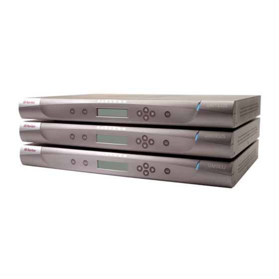
1: I HAPTER NTRODUCTION Product Photos Figure 2 Paragon II Main Switching Units Figure 3 P2-UMT832 , P2-UST , and P2CIM-APS2 Figure 4 P2-EUST... -
Page 14: Product Features
• Supports the use of a Kensington Expert Mouse® and Turbo Mouse trackball (Model #: 64210) at the local site when used with the following Paragon II components. − User Station: P2-UST or P2-EUST −... - Page 15 NTRODUCTION Special Note: Paragon II Release 4.2 is not compatible with the Paragon II System Controller. Release 4.2 is considered a “standalone” release and is not supported for installation in a Raritan PCCI environment. PCCI integration is planned for an upcoming release.
-
Page 16: Package Contents
One 6-ft. (1.8-m) AC power cord • RUMT-1U-LM304 Rackmount kit • CAT5 admin cable • Raritan’s “User Manuals & Quick Setup Guides” CD • Quick Setup and Installation Guide The Paragon Stacking Unit (S Unit) ships with: • One Stacking Switch •... -
Page 17: Chapter 2: Installation
2: I HAPTER NSTALLATION Chapter 2: Installation Important: The Paragon and all devices you want to attach to it must be unplugged and powered OFF prior to installation. Basic Installation S Unit Optional M Unit P2-UST or P2-EUST Figure 5 Installation Diagram 1. -
Page 18: Initial Administrative Verification
User Station’s attached monitor; the Login screen appears. Type admin in the User Name field and press Enter. Type raritan (all lowercase) in the Password field and press Enter. Note: The factory-default user names for regular users are user01 through up to user15 (depending on the model of your Main Switching Unit), and for the administrator is admin. -
Page 19: Paragon Ii Front Panel Display And Controls
(if any) to access. Paragon II Front Panel Display and Controls The control buttons and LCD display on the Paragon II unit provide system management and technical support functions. For most situations, there is no need to use the front panel beyond viewing status. -
Page 20: Figure 9 Lcd Normal Display
Figure 9 LCD Normal Display Power Up Option: If you hold down the FUNC button on the front panel of the Paragon II unit during Power Up, the Paragon II unit will clear its database and reset to factory defaults. Confirm functions by pressing the ENT button on the front panel. -
Page 21: Figure 11 Lcd Functions
Figure 11 LCD Functions Selecting a Function: Press the FUNC button on the front panel of the Paragon II unit to enter Function Menu mode and use the buttons to scroll through the Function List. Press the ENT button on the front panel to select one displayed function and use the instructions below for each specified function. -
Page 22: Figure 15 Channel Cim (Ukvm) Test
Searching Now… Figure 18 Auto Configure 8. Set IP Address: As an administrator, you may change Paragon II’s IP address directly from the front panel of the device. The Paragon II’s current IP address will be displayed, along with a cursor. Use the keys to move the cursor over digit-by-digit, and use the keys to change the value of that digit. -
Page 23: Figure 19 Data Update Message
You cannot configure one using the front panel controls on the units. 9. Reset Unit (Paragon II matrix switch): Enables restart of Paragon II unit as if the unit’s power is physically turned off and back on again. -
Page 24: Initial Configuration
Basic Installation to install a simple Paragon system with a single matrix switch. See Appendix B: User Station Direct Mode, to install a “direct mode” User Station-to-CIM system with no matrix switches. See Chapter 5: Paragon II and P2ZCIMs to install a Z-CIM and a local PC in your system. - Page 25 Toggle the display of all channel ports (including inaccessible ones) on or off View the Unit Status Menu for connected Raritan Remote Power Control unit (available only from Power Control Menu) Toggle the Selection Menu’s sorting way: numerically by...
-
Page 26: Installing A Paragon System With A Single Matrix Switch
OSUI to login, select servers, or administer the system. Figure 21 Login Screen for Paragon II If the monitor instead displays a “..No connection to Paragon..” message, the User Station is not properly connected to the matrix switch. -
Page 27: Figure 22 Selection Menu
15-pin female video port and 6-pin mini-DIN mouse and keyboard ports on the server. AUATC (serial servers, routers, etc.): Please see Appendix E: Connecting Serial Devices to Paragon II System for installation instructions. Z-CIM and P2ZCIM (local single-user IBM PS/2 compatible servers): Please see Chapter 5: Paragon II and P2ZCIMs for installation instructions. -
Page 28: Figure 23 Administration Menu
II U ARAGON UIDE Note: If your video image is fuzzy (especially if you are using an LCD flat-panel monitor), you can adjust the video gain to focus the video image. If the OSUI is not displayed, activate it by pressing the Scroll Lock key twice QUICKLY, then use the + and – (plus and minus) keys on the numeric keypad to adjust the video image until it appears to be in focus. -
Page 29: Installing A Cascaded Paragon System
NSTALLATION Installing a Cascaded Paragon System Paragon II’s channel port capacity can be expanded by installing a cascade of matrix switches (Main Switching Units). In a “two-tiered” cascaded system, one or more subsidiary matrix switches are connected to the channel ports of a Base Unit (first tier -- Master matrix switch). If you fully populate a second tier, you can add a third tier by connecting additional subsidiary matrix switches to the channel ports of matrix switches in the second tier. -
Page 30: Figure 26 Selection Menu
A. At the Login screen, type admin in the User Name field and press the Enter key. In the Password field, type the default password raritan (all lowercase) and press the Enter key. B. The monitor will display the Selection Menu, indicating that the User Station is correctly installed. -
Page 31: Figure 27 Administration Menu
2: I HAPTER NSTALLATION C. Press F5 to activate the Administration Menu. Use the keys to move the highlight to the Channel Configuration entry and press Enter to select it. Figure 27 Administration Menu D. The Channel Configuration menu appears. Use the keys and Page Up and Page Down keys to approach channel ports to which subsidiary matrix switches are connected. - Page 32 FUNC on the unit’s front panel until “Clear Database Hit Ent/ESC?” appears on the LCD panel. Press the ENT and the ESC buttons sequentially to execute a partial reset on the database. Please see the “Reset Uni” section in “Paragon II Front Panel Display and Controls” in Chapter 2 for additional information.
-
Page 33: Installing The Paragon P2-Umt832S Stacking Unit
2: I HAPTER NSTALLATION Installing the Paragon P2-UMT832S Stacking Unit 1. Make sure all Paragon switching units are powered OFF. 2. Connect a power cord to a Stacking Unit. 3. Connect one end of a stacking cable to "Expansion Port Out" on the back of the Stacking Unit. Connect the other end of the cable to "Expansion Port"... -
Page 34: Installing A Hubpac
5. Then power on the Main Switching Unit. Installing a HubPac P2-HubPac is available for use with Paragon II. HubPac units allow users of different Paragon switching units to access the same server(s). Each five-port cluster on a HubPac is capable of connecting a server to up to four Paragon matrix switches. -
Page 35: Figure 29 Connecting A P2-Umt1664M To A Hubpac
2: I HAPTER NSTALLATION Installing a HubPac Please use the Basic Installation instructions below to create the HubPack configuration that gives users of up to 4 Paragon switching units the capability to access the same server(s). Figure 29 Connecting a P2-UMT1664M to a HubPac 1. - Page 36 II U ARAGON UIDE A. Connect one end of a Category 5e UTP cable to the RJ45 X-1 port on the back of HubPac. B. Connect the other end of the cable to channel port # N on the back of one of the desired Paragon matrix switches.
-
Page 37: Chapter 3: Operation - User Functions
Scroll Lock) twice in QUICK succession. Login Log on to Paragon II so you can access servers and other devices connected to the Paragon II system. The Login screen is automatically displayed on every User Station monitor after the single or Master Paragon II matrix switch (Base Unit) is powered on. To activate the Login screen on a user-station monitor at any other time, press the system’s hot key (factory default:... -
Page 38: Figure 31 Selection Menu For A P2-Umt442
Help Menu section later in this chapter. Figure 31 Selection Menu for a P2-UMT442 Note: To Log out of the Paragon II system, press F9 while the OSUI is on-screen. Below are the function keys used when working with the OSUI:... -
Page 39: Video Gain And Skew Compensation
3: O – U HAPTER PERATION UNCTIONS Video Gain and Skew Compensation When traveling the distance from the target server to the monitor connected to a User Station over different cables, Red, Green, and Blue (RGB) color signals may arrive at different times, causing color separation on your monitor;... -
Page 40: Video Gain Adjustment In P2-Ust
II U ARAGON UIDE Video Gain Adjustment in P2-UST A video-gain adjustment is available to focus the video image, which can be especially useful if you are using an LCD flat-panel monitor. To make this adjustment, activate the OSUI by pressing the hot key (default: Scroll Lock) twice QUICKLY, if you have not done so already. -
Page 41: Selecting A Server
Use the Page Up and Page Down keys on your keyboard to move between the pages. Once you have selected a server as described on the following pages, Paragon II will switch to that channel port. If “ID Display” is enabled in the User Profile configuration, a display will... - Page 42 4. Press Enter If it is a server attached to the chosen channel port and you are permitted to access it, Paragon II automatically switches you to that channel port for normal server operation, and the OSUI disappears. If it is a cascaded tier device attached to that channel port, an OSUI Selection Menu specific to that tier device will appear;...
- Page 43 Channel port is unavailable, currently being accessed by another user. (This happens only when the Paragon II system is in Private Mode.) A blocked matrix switch will be in red in the Selection Menu (in order of channel number) either.
-
Page 44: Manually Selecting The Access Path
3E3, you can manually choose a path to access a target server in the channel number view. For older Paragon I or Paragon II products to support this feature, see the note in the end of this section for more information. -
Page 45: Figure 37 Selection Menu After Manually Selecting The Access Path
The desired server is accessed in the channel name view instead of the channel number view. • The path passes through Paragon II products with the firmware version older than 3E3. You must upgrade their firmware to support this function. See Chapter 8: Firmware Upgrade for more information. -
Page 46: Path Overlapping Constraint
II U ARAGON UIDE Path Overlapping Constraint The path you manually choose may completely or partially overlap a path having been selected by another user in the PC Share or Public View mode. In this case, Paragon either limits your server accessibility to the one accessed by the user with whom you share the path or disallow any server accessibility. -
Page 47: Figure 40 Path Overlapping Instance 2
3: O – U HAPTER PERATION UNCTIONS Result: All servers connected to UMT-3 are inaccessible to the UST-2 user. Server 1 Server 2 UMT-3 overlapping UMT-2 Overlapping UMT-Base UST-2 UST-1 Figure 40 Path Overlapping Instance 2 Result: Only Server 1 on UMT-3 is accessible to the UST-2 user Server 1 Server 2 UMT-3... -
Page 48: User Profile Customization
User Profile screen. To access this menu, press F4 when the OSUI is active. This menu displays Paragon II’s configuration and allows you to set preferred operating parameters for individual user accounts or for a group of accounts, as Administrator, or change your profile as a logged-in User. -
Page 49: User Profile Parameters And How To Change Settings
User Profile Parameters and How to Change Settings • Scan Mode: Indicates how Paragon II determines the length of time to pause at each channel port during autoscanning. Default setting is “Global” – the system pauses at each channel port for the same length of time set in the Global Scan Rate field. “Individual” setting indicates that the Administrator has set a specific length of time for each individual channel ports (as displayed in the Selection Menu). -
Page 50: Figure 45 Prompt In Message Bar To Save Changes
II U ARAGON UIDE all times. The default setting is 03. If the ID Display is set to “Off,” the number in this field will have no effect. • Sleep Mode: A power-saving mode that is activated once a user logs in. Sleep mode acts as a screensaver if the User Station is idle (no keyboard or mouse activity) for a specified amount of time. -
Page 51: Help Menu
3: O – U HAPTER PERATION UNCTIONS Help Menu When the OSUI is open, activate the Help Menu by pressing F1. This menu displays a list of the function keys and their help functions. Figure 46 Help Menu... -
Page 52: Keyboard-Controlled Osui Functions
Administrator only: Toggle autoscan on or off Administrator only: Toggle autoskip on or off View the Information Menu to see the version numbers of the Paragon II’s firmware and hardware, the number of accessible matrix switches, the total number of accessible servers, etc. -
Page 53: Information Menu
3: O – U HAPTER PERATION UNCTIONS Information Menu When the OSUI is open, activate the Information Menu by pressing F8. This menu displays the “vital statistics” of the User Station that you are using, including its firmware, hardware, and FPGA revisions, its serial number, which console port (user port) and port number on the matrix switch attached to it, and the number of KVM switches and PCs (servers) that can be accessed through it. -
Page 54: Concurrent Multiple Video Outputs
Paragon II system administrator. Illustration Example: Four channels (number 2, 4, 6 and 7) of Paragon II system are connected to the same server which has multiple video ports. The Paragon administrator has configured these four channels as an association group in Paragon Manager, and Channel 4 is set as the “first”... -
Page 55: Naming Convention For Multiple Video
CIM is connected to one USB port. If there are not enough USB ports on the server, connect their USB connectors to a USB hub’s USB ports for power supply. 3. Connect these CIMs to the channel ports of the desired Paragon II unit using the Cat 5 cables. Operation Rules This section describes the general concept for operating the Multiple Video function, including the activation of the function and exiting the Multiple Video mode. -
Page 56: Messages On The Activator User Station
ARAGON UIDE • This function can be remotely triggered through Raritan’s IP-Reach (if any). Note: Accessing the ACTIVATOR channel with the Forced Video command CANNOT trigger the Multiple Video function. The associated channels will not output their data automatically. Exit the Multiple Video Mode The hot key for triggering the OSUI is disabled on FOLLOWER User Stations. -
Page 57: Messages On The Follower User Stations
3: O – U HAPTER PERATION UNCTIONS • Mouse/keyboard activity is detected on the FOLLOWER User Station(s) when the Multiple Video command is issued. Paragon will NOT execute Multiple Video in order to protect that server’s operation. • The FOLLOWER User Station is P2-USTIP which enters the remote mode (no OSUI displayed). - Page 58 II U ARAGON UIDE...
-
Page 59: Chapter 4: Operation - Administrator Functions
The default password for the admin user is raritan, all lowercase, but we recommend this password be changed as soon as Paragon II is initially installed (see User Profile Parameters and How to Change Settings in Chapter 3 for additional information). -
Page 60: Guidelines For System Configuration
Figure 52 System Configuration Menu for P2-EUST • Device ID: Type in the desired name for the single or Master Paragon II matrix switch (Base Unit). It is important for matrix switches in a “cascaded system with multiple matrix switches” to have distinctive names, so that users can tell them apart. (The system will assign... - Page 61 OSD of local user ports, and also appears with inactive status in other Raritan clients that operate with Paragon II, such as Paragon Manager, RRC/MPC, PIISC, and CC. If Ghosting is set to Enable, when an active CIM is removed from one channel port and connected to another channel port (‘hot-swapped’), you will see...
-
Page 62: Video Redirection (Forced Video)
Paragon Manager. In addition, with Paragon Manager, you can connect to multiple Paragon II units at one time and remotely operate the Forced Video function. See Paragon Manager User Guide for additional information. -
Page 63: Operating Forced Video Using Osui
You are operating on the User Station 1 (UST-1). Now you can issue the Forced Video command to direct one server to output its data to one of the User Stations connected to the same Paragon II matrix switch as your UST-1. Note that you cannot direct the server output its data to User Stations connected to a Paragon matrix switch other than the Base Unit, such as UST-A or UST-B in the diagram below. -
Page 64: Operating Forced Video Using Paragon Manager
You can also use Paragon Manager in a remote PC to redirect the video/keyboard/mouse output. Paragon Manager can connect to multiple Paragon II units of different models so you can operate Forced Video by switching between different units. For more information, see Paragon Manager User Guide. -
Page 65: User Station Receiving Forced Video
DMINISTRATOR UNCTIONS Guidelines • When Paragon Manager is connected to one Paragon II unit, do NOT connect Paragon Manager to that unit’s upper tier(s) again. Figure 56 Paragon Manager Connection to Different Paragon Units • There are two upper limits for the number of units to which Paragon Manager can connect at one time. -
Page 66: Channel Association For Multiple Video
• This function applies to both Paragon II Main Switching and Stacking Units. • Channel ports of the same association group are all on the same Paragon II Main Switching Unit (either with or without any Stacking Units connected). •... -
Page 67: User Configuration
4: O – A HAPTER PERATION DMINISTRATOR UNCTIONS User Configuration To view the current connection status for each user and to add, delete, and edit user names and security rights, select option 2, User Configuration, from the Administration menu. Figure 59 Left Panel of the User Configuration Menu This menu displays one user’s information in each row. -
Page 68: Figure 60 Right Panel Of The User Configuration Menu
127 (512 with an added memory card). • Delete a user by moving the highlight to a user name and pressing Delete. Paragon II will ask for confirmation; if you respond by pressing Y, that user account will be deleted from the system. -
Page 69: Channel Configuration
To edit or initialize a P2CIM, change the device name, individual scan rate, device type, and group IDs associated with each server or device, select option 3, Channel Configuration, from the Administration Menu. When you save Channel Configuration changes, Paragon II will update each affected P2CIM as necessary. -
Page 70: Figure 62 Right Panel Of The Channel Configuration Menu
II U ARAGON UIDE While the cursor is in the Device column, press Tab or key to move to the right panel of this menu and display device group information: The Group columns display which groups (if any) the device has been assigned to. Figure 62 Right Panel of the Channel Configuration Menu... -
Page 71: Video Display Adjustment For P2-Eust
4: O – A HAPTER PERATION DMINISTRATOR UNCTIONS Video Display Adjustment for P2-EUST The P2-EUST has additional capabilities for allowing adjustment of your video display. Specify skew levels for Automatic Gain Control (AGC), Red (R), Green (G), and Blue (B) to improve video quality. -
Page 72: User Station Profile
At this time, set a video delay for channel port switching at your User Station. If you set the video delay to any number of seconds greater than zero, Paragon II will wait until a video signal is constant for that number of seconds before passing it through to the monitor. To... -
Page 73: Group Settings (Access Rights)
4: O – A HAPTER PERATION DMINISTRATOR UNCTIONS Group Settings (Access Rights) To assign access rights to users and security levels to servers in a Paragon system, assign users to user groups with defined rights and servers to channel port groups with defined accessibility. Each group can contain multiple users or servers. -
Page 74: Recommendations
II U ARAGON UIDE HESE USER GROUPS CAN ACCESS THESE CHANNEL PORT GROUPS 00 through 99 (all servers) 0x (01 through 09) 00, 0x, and x0 through x9 For example: 01 can access 00, 01, and 10 through 19; 02 can access 00, 02, and 20 through 29, etc. xy (10 through 99) 00, 0x, and xy For example:... -
Page 75: System Reboot And System Reset
Ready-to-Reset report to Paragon clients (P2SC, Paragon Manager, UST-IP, etc.) as an event log. System Reboot To reboot your Paragon II from the OSUI, select option 5, System Reboot, from the Administration Menu, and press Enter. Figure 66 System Reboot A message in the message bar asks you to confirm the System Reboot command. -
Page 76: System Reset
II U ARAGON UIDE System Reset To reset the Device Name, Network Settings, User Profiles, System Configuration, and Channel Configuration, returning them to the original factory default values, without having to physically go to each switch to reset it, select option 6, System Reset Settings, from the Administration Menu. -
Page 77: Network Settings
Use the arrow keys to scroll over to each byte and change the IP as needed. The default IP address is 192.168.0.192. • Net Mask: The net mask for the Paragon II unit is set at a default value of 255.255.255.0. Reset this as necessary. •... -
Page 78: Autoscan And Autoskip
System Configuration in this chapter). To force the system to skip over vacant channel ports, an administrator must turn on autoskipping. After logging into Paragon II, administrators can press F7 to turn autoskipping on and off. When autoskipping is on, Paragon will automatically skip vacant channel ports during autoscanning or when a user tries to switch to such a port manually. -
Page 79: Configuring And Naming The Power Strip
UNCTIONS Configuring and Naming the Power Strip Activate the Paragon II OSUI by logging into the system or pressing the hot key (default: Scroll Lock) twice quickly. The new power strip should appear in the appropriate channel port with the name PCR8, PCS12, or PCS20, depending on the model type. -
Page 80: Paragon Ii Network Port
”No Outlets / Access Denied” message appears and the action is cancelled. • If Paragon II sees that this server is associated with at least one power outlet, it will switch to that server. The OSUI will remain on-screen, displaying a list of power outlets associated with the specific server. - Page 81 4: O – A HAPTER PERATION DMINISTRATOR UNCTIONS Note: The Ethernet port on the Paragon II is hard coded (not configurable) and supports 10-BaseT/Half duplex only.
- Page 82 II U ARAGON UIDE...
-
Page 83: Chapter 5: Paragon Ii And P2Zcims/Z-Cims
UKVMSC), enable access and control of multiple servers from a Paragon User Station, occupying only one channel port on your Paragon II unit. P2ZCIMs or Z-CIMs are set up in a chain-like server-to-server arrangement, with each P2ZCIM or Z-CIM connected to the keyboard, video, and mouse ports of each server and linked with standard Cat5 UTP cables. -
Page 84: Paragon Ii And P2Zcims
F12 key. Connect a P2ZCIM as a Tier: 1. Connect a Category 5e UTP cable to the channel port on the Paragon II matrix switch reserved for the P2ZCIM chain. 2. Connect the other end of this Category 5e UTP cable to the UTP OUT (O) port on a P2ZCIM, which will be the first P2ZCIM in the chain. - Page 85 P2ZCIM is properly configured.. Name the Server Channel on the Tiered Selection Menu of P2ZCIM 1. When viewing the Paragon II Selection Menu or any OSUI menu, press F5 to go to the Administration Menu. 2. Select the Channel Configuration submenu, and press Enter.
-
Page 86: Figure 71 Resizing The P2Zcim Chain
At a User Station Login Menu, type admin in the User Name field and press ENTER. Type raritan or your new password in the Password field and press ENTER. If the Selection Menu is not in the channel number view, press F12 to toggle the view. -
Page 87: P2Zcim Led Status
1664 with hardware III and Paragon II firmware, and Paragon II matrix switches; in chains up to 20 individual P2ZCIM units at least one P2ZCIM must be powered ON; In P2ZCIMs chains from 21 to 42 ZCIM units, at least 15 P2ZCIMs must be powered ON. -
Page 88: Paragon Ii And Z-Cims
Back of P2-UMT832 Figure 73 Connecting Z-CIMs or P2ZCIMs as Tiers All Paragon II components must be powered ON prior to Z-CIM tier installation. All servers and components in the Z-CIM chain must be powered OFF prior to installation. When following the installation and configuration instructions below, sort the Selection Menu by channel number, not by name. - Page 89 ARAGON Connect a Z-CIM as a Tier 1. Connect a Category 5e UTP cable to the channel port on the Paragon II unit reserved for the Z-CIM chain. 2. Connect the other end of this Category 5e UTP cable to the UTP OUT port on a Z-CIM, which will be the first Z-CIM in the chain.
-
Page 90: Using A Ukvmspd Z-Cim With A Local Pc
For Paragon I UMT242, 442, 832 and 1664 with hardware III and Paragon II firmware, and Paragon II matrix switches; in chains up to 20 individual Z-CIM units at least one Z-CIM must be powered ON; In Z-CIMs chains from 21 to 42 Z-CIM units, at least 15 Z-CIMs must be powered ON. -
Page 91: Figure 74 User Profile Menu
5: P P2ZCIM /Z-CIM HAPTER ARAGON 3. Press F4 to activate the User Profile Menu. Figure 74 User Profile Menu 4. Use Tab or the keys to move the highlight to the Local PC field. 5. Press Enter. The Local PC field will turn green. 6. - Page 92 II U ARAGON UIDE...
-
Page 93: Chapter 6: Managing Ibm Bladecenter Servers
Paragon treats one IBM BladeCenter chassis as one tier device similar to the Z-CIM chain. However, Paragon II does not detect and display the real-time blade server status in the OSUI as it does to the Z-CIM chain. You must issue a refresh command for the following scenarios: •... -
Page 94: Renaming A Bladecenter Chassis
II U ARAGON UIDE 9. Press F2 to go to the Selection Menu and verify that blade server status has been updated. Green channels indicate that there is a blade server installed and it is powered on; black channels indicate that either there is no blade server installed or the installed blade server is powered off. -
Page 95: Renaming A Blade Server
6: M IBM B HAPTER ANAGING LADE ENTER ERVERS 7. Press F2 to verify the new name in the Selection Menu. Renaming a Blade Server By default, each of IBM BladeCenter server is named as “IBM-Blade01,” “IBM-Blade02,” and so on. 1. - Page 96 II U ARAGON UIDE...
-
Page 97: Chapter 7: Configurations
7: C HAPTER ONFIGURATIONS Chapter 7: Configurations The aim of the Main Switching Units (UMT “M”) and Stacking Units (UMT “S”) is to allow users to build the Paragon system to include additional channel ports and the tiers up to three levels, so that more users and channels can be configured to control more servers. -
Page 98: Tiered Configurations
A maximum of three (3) tiers, including the Base Unit, is permitted. • Devices that are not Paragon II matrix switches but come with two or more channel ports, such as Raritan MasterConsole, CompuSwitch, Z-CIM, or P2ZCIM, are treated as tier devices. -
Page 99: Figure 79 Single Base Configuration
7: C HAPTER ONFIGURATIONS Non-UMT tier Non-UMT tier UMT-3A UMT-3B device-3A device-3B Non-UMT tier UMT-2A UMT-2B Non-UMT tier device-2A device-2B UMT-Base Figure 79 Single Base Configuration... -
Page 100: Stacked Configurations
II U ARAGON UIDE Guidelines for Multiple Base Configuration A multiple base configuration could be two-tier or three-tier configuration. It is composed of more than one Paragon UMT “M” Base Units and second-tier or even third-tier devices. Initialization − After all devices have been connected, power on the devices from UPPER tier to lower tier. - Page 101 Paragon II product in a closed configuration system. • A Paragon I product with hardware version HW3 (running Paragon II firmware) can accommodate only one Stacking Unit. Note: The easiest way to determine if the hardware version of your Paragon I unit is HW3 is to check the number of its stacking ports on the rear side.
-
Page 102: Standard Stacking Configurations
II U ARAGON UIDE Standard Stacking Configurations Single Base with Stacking Example A: Non-blocked System – P2-UMT1664M Standard configuration – any user can access any channel port in the system. P2-UMT1664M P2-UMT1664S P2-UST P2-UST Figure 81 Stacking - Single Base Configuration with P2-UMT1664M and P2-UMT1664S Example B: Non-blocked System –... -
Page 103: Figure 84 Stacking - Single Base Configuration With P2-Umt832M And P2-Umt832S
7: C HAPTER ONFIGURATIONS Example D: P2-UMT832M -- Stacked and Tiered Standard configuration – any user can access any channel port in the system. UMT 3A UMT 3B UMT 3C UMT 3D UMT 3E UMT 2A UMT 2B UMT 2C UMT 2D UMT 2E I/P O/P... -
Page 104: Figure 86 Illegal Stacking - Single Base Configuration With P2-Umt1664M And P2-Umt1664S
II U ARAGON UIDE Example F: ILLEGAL Configuration I/P O/P P2-UMT1664M P2-UMT1664S P2-UMT1664S P2-UST P2-UST Figure 86 ILLEGAL Stacking - Single Base Configuration with P2-UMT1664M and P2-UMT1664S Example G: ILLEGAL Configuration P2-UMT832S 1A P2-UMT1664M P2-UMT832S 1B P2-UST P2-UST Figure 87 ILLEGAL Stacking - Single Base Configuration with P2-UMT1664M and P2-UMT832S Example H: ILLEGAL Configuration P2-UMT1664M P2-UMT1664S... -
Page 105: Non-Standard Tier Configuration
After any re-connection subsequent to the Non-Standard tier configuration, all UMTs should undergo a FUNC reset to clear the database. See Reset Unit under Paragon II Front Panel Display and Controls in Chapter 2 for more information on clearing the database. -
Page 106: Figure 90 Single Diamond Configuration
After re-connection, all UMTs should undergo a FUNC reset to clear the database. See Reset Unit under Paragon II Front Panel Display and Controls in Chapter 2 for more information on clearing the database. This procedure should be performed starting from the third-tier device down to the Base Unit. -
Page 107: Figure 92 Redundant Configuration
After installation, all UMTs should undergo a FUNC reset to clear the database. See Reset Unit under Paragon II Front Panel Display and Controls in Chapter 2 for more information on clearing the database. This procedure should be performed starting from the third-tier device down to the Base Unit. -
Page 108: Loop-Back Configuration
II U ARAGON UIDE In order to make a redundant configuration system operate more efficiently, the following connection scheme between tiers is recommended: − Assume there are two UMT Base Units: UMT-Base 1 and UMT-Base 2 − Assume there are three UMT second-tier devices: UMT-2A, UMT-2B, and UMT-2C −... -
Page 109: Chapter 8: Firmware Upgrade
STEP 1: Download the Latest Firmware 1. Use your browser to visit Raritan’s Firmware Upgrades Web page: http://www.raritan.com/support/sup_upgrades.aspx. 2. Click Paragon II to locate the latest firmware version for the device you want to upgrade. 3. Click that firmware. 4. Click START DOWNLOAD. -
Page 110: Failsafe Upgrade Feature
For details on the operation of the Paragon Update utility, see Paragon Manager User Guide. Failsafe Upgrade Feature In the past, whenever a firmware update failure occurred on the Paragon II Main Switching Unit, Stacking Unit or a P2-UST User Station, a return to Raritan is required for function restoration. -
Page 111: Figure 95 Main Switching Unit -- Boot Loader Successfully Upgraded
Main Switching Unit with the latest firmware whose name begins with “P2-”. Verify the Firmware Version Use the Function Menu on the Front Panel to check the firmware version. See Paragon II Front Panel Display and Controls in Chapter 2 for more information. -
Page 112: Stacking Units
Unit for failsafe capability requires these requisites: • Keep only one Stacking Unit connected to the Main Switching Unit at one time. • The Main Switching Unit must be implemented with Paragon II 4.2 firmware or later as detailed below. IRMWARE ERSION... -
Page 113: User Stations
3. Stacking Unit automatically restarts itself after the update completes. Verify the Firmware Version Use the Function Menu on the Front Panel to check the firmware version. See Paragon II Front Panel Display and Controls in Chapter 2 for more information. - Page 114 II U ARAGON UIDE Recovering User Stations after Upgrade Failure As long as your User Station has the failsafe capability, you can restore its function whenever the upgrade failure occurs. 1. Power cycle the User Station. 2. Repeat the same upgrade process until the upgrade is finished successfully.
-
Page 115: Appendix A: Specifications
A: S PPENDIX PECIFICATIONS Appendix A: Specifications ARAGON ESCRIPTION IMENSIONS EIGHT OWER P2-UMT1664M 16 users x 64 server 17.32" (W) x 11.41" (D) x 3.5" (H) 12.52 lbs 100V/240V ports, expansion slot, 440mm (W) x 290mm (D) x 89mm (H) 5.68 kg 50/60 Hz 0.6A stacking port, network... - Page 116 II U ARAGON UIDE ARAGON ESCRIPTION IMENSIONS EIGHT CIMS P2CIM-APS2 CIM for PS/2., provides 1.3” (W) x 3.0” (D) x 0.6” (H) 0.20 lb automatic skew 32mm (W) x 77.4mm (D) x 15.6mm (H) 0.07 kg compensation with P2- EUST P2CIM-APS2-B CIM for IBM 1.3”...
-
Page 117: Cat5 Cable Guidelines
A: S PPENDIX PECIFICATIONS CAT5 Cable Guidelines Use only straight-through-pinned four-pair (eight-wire) Category 5 unshielded twisted pair (UTP) cables, terminated with standard RJ45 plugs, for the CAT5 cabling links in your Paragon system. If your existing CAT5 site-wiring system meets these requirements, feel free to send the signals through your site’s patch panels, existing wiring, etc., but you should keep the number of patches and splices to a minimum to avoid degrading the video signals. - Page 118 II U ARAGON UIDE...
-
Page 119: Appendix B: User Station Direct Mode
B: U PPENDIX TATION IRECT Appendix B: User Station Direct Mode A Paragon User Station set to Direct Mode can be directly connected to a Paragon CIM, either temporarily for emergency “crash cart” access or permanently for non-switched extension purposes, without having to go through a Paragon Base Unit. To create a “Direct Mode”... - Page 120 II U ARAGON UIDE...
-
Page 121: Appendix C: Tiering And Compatibility
C: T PPENDIX IERING AND OMPATIBILITY Appendix C: Tiering and Compatibility Tiering Matrix BASE TIER UMT x HW2 UMT x HW3 with UMT x HW3 with P2-UMT1664M/ 3A3 Firmware 3.2 Firmware 832M/442/242 P2-UMT1664M / 832M/442/242 P2-UMT1664S/832S Stack Stack UMT x HW3 with 3.2 Firmware UMT x HW3 with 3A3 Firmware... -
Page 122: Compatibility Matrix
II U ARAGON UIDE Compatibility Matrix Paragon I Paragon II Feature/Component HW2/2Z HW3 (3A3 HW3 ( P2 HW4M or above Firmware) Firmware) Y-CIMs C, P, PD CIMs UKVMSPD Z-CIMs P2ZCIMs P2-EUST (UMT-3E0 and (UMT-3E0 and above) above) P2-UST (V5) (UMT-3B0K and... -
Page 123: Double Diamond Configuration
Officially, the Double Diamond configuration is NOT a Raritan-approved solution if stacking units or P2-HubPac is included in the configuration. Therefore, it is highly recommended to avoid this configuration especially when using Paragon II stacking units or the P2-HubPac. UMT-3A... - Page 124 II U ARAGON UIDE...
-
Page 125: Appendix D: Paragon Ii Rack Mount
OUNT Appendix D: Paragon II Rack Mount Paragon II User Stations and most matrix switches can be mounted in 1U (1.75", 4.4 cm) of vertical space in a standard 19" equipment rack, except that P2-UMT1664M matrix switch shall be mounted in 2U (3.5", 8.9 cm) of space. To rackmount a matrix switch, use the brackets and screws that came with the unit;... -
Page 126: Rear Mount
II U ARAGON UIDE Rear Mount 1. Secure the cable-support bar to the front end of the side brackets, near the side brackets’ “ears,” using two of the included screws. 2. Slide the User Station or matrix switch between the side brackets, with its rear panel facing the cable-support bar, until its front panel is flush with the back edges of the side brackets. -
Page 127: Appendix E: Connecting Serial Devices To Paragon Ii System
To connect an ASCII serial device, LAN/WAN component or a server through a serial port (RS-232) to Paragon II system, use one of our serial CIMs. They are P2CIM-SER, P2CIM-SER- EU and AUATC. These CIMs can emulate an ASCII terminal and convert the serial data from the ASCII device to VGA video (800x600x60) and PS/2 keyboard signals. -
Page 128: Operating A Serial Cim
• Buffer Edit -- Buffer displayed. (Pressing Alt+F4 enters buffer review/edit mode.) Raritan provides a detailed user guide about the operation and configuration of the two CIMs. Please see Paragon and Dominion KX Serial Device CIM User Guide for additional information. -
Page 129: Figure 104 Auatc Screen Layout (On Line Mode)
E: C II S PPENDIX ONNECTING ERIAL EVICES TO ARAGON YSTEM Figure 104 AUATC Screen Layout (On Line Mode) • In line 1 of the top pane, AUATC’s firmware version is displayed at the right. • In line 3 of the top pane, the cursor position and buffer-page number are displayed at the left and the terminal type and data rate are displayed at the right. - Page 130 Conveniently, you may program any of the PC keyboard’s twelve function keys to trigger your most-often-used data-stream commands. Pressing any key set this way causes Paragon II to send the corresponding command to the device. During the online session, you can also send any of the following key combinations (press and hold Ctrl or Alt, press and release the command key, and release Ctrl or Alt) to control your communication with the device or to access AUATC’s help...
-
Page 131: Figure 105 Help Screen
E: C II S PPENDIX ONNECTING ERIAL EVICES TO ARAGON YSTEM Help Mode Figure 105 Help Screen... -
Page 132: Figure 106 Buffer Edit Mode Screen
II U ARAGON UIDE Buffer Edit Mode AUATC stores the most recent eight pages of data from the attached ASCII device in a circular buffer. After switching the AUATC from On Line Mode to Buffer Edit Mode by pressing Alt + F4, you can review the contents of the buffer by moving the cursor with the arrow keys, Page Up , Page Down , Home, and End. -
Page 133: Configuring Auatc
E: C II S PPENDIX ONNECTING ERIAL EVICES TO ARAGON YSTEM Configuring AUATC Press Alt + F2 to activate the Setup Screen, where you can select your desired serial- communication parameters (baud rate, etc.) and type of local video output. The initial parameters will always start at their factory defaults, so make sure that the serial port or device to which AUATC is attached is temporarily configured for 9600 bps, 8 data bits, no parity, and 1 stop bit. -
Page 134: Figure 108 Set Up Programmable Keys Screen
II U ARAGON UIDE To program any of your keyboard’s twelve function keys with commands or data items you frequently have to send the device, activate the Set Up Programmable Keys screen by pressing Alt + F3. Once a string (with a maximum length of sixteen characters) has been assigned to a key, pressing that key while in On Line Mode will send the entire string to the device. -
Page 135: Troubleshooting Auatc
E: C II S PPENDIX ONNECTING ERIAL EVICES TO ARAGON YSTEM Troubleshooting AUATC If you do not get a device prompt: 1. If AUATC’s screen is displayed on your monitor with the top and bottom help windows, make sure that it indicates On Line status. If not, press Esc to return to On Line Mode. 2. - Page 136 II U ARAGON UIDE...
-
Page 137: Appendix F: Extra Keyboard/Mouse Information And Settings
F: E PPENDIX XTRA EYBOARD OUSE NFORMATION AND ETTINGS Appendix F: Extra Keyboard/Mouse Information and Settings Emulating Sun Keys with a PS/2 Keyboard We recommend that you use a Sun keyboard and mouse at your User Stations if there are any Sun servers in your Paragon system. -
Page 138: Usb Keyboard Layout Settings (P2Cim-Ausb, P2Cim-Ausb-B Or P2Zcim-Usb)
II U ARAGON UIDE USB Keyboard Layout Settings (P2CIM-AUSB, P2CIM-AUSB-B or P2ZCIM-USB) When you attach the server with a USB CIM and your keyboard is not US English (code 33), you will have to change the keyboard layout setting. You need to press different hot key combinations to enter the setting mode based on your CIM types. -
Page 139: Sun Keyboard Layout Settings (P2Cim-Sun Or P2Cim-Asun)
F: E PPENDIX XTRA EYBOARD OUSE NFORMATION AND ETTINGS 5. Either press Esc to exit the setting mode or close the text editor. Generic Keyboard Layout Code ANGUAGE AYOUT ANGUAGE AYOUT Arabic Netherlands Belgian Norwegian Canadian-Bilingual Persian Canadian-French Poland Czech Republic Portuguese Danish Russia... -
Page 140: Sun Keyboard Layout Settings (P2Zcim-Sun)
II U ARAGON UIDE 6. Either press Esc to exit the setting mode or close the text editor. Sun Keyboard Layout Code OUNTRY AYOUT OUNTRY AYOUT Canada Fr5 Netherland5 Canada Fr5 Tbits5 Norway5 Czech5 Poland5 Denmark5 Portugal5 Estonia5 Russia5 France5 Spain5 Germany5 Sweden5... -
Page 141: Switching Between 101 And 102 Keys (P2Cim-Aps2)
F: E PPENDIX XTRA EYBOARD OUSE NFORMATION AND ETTINGS 5. Either press Esc to exit the setting mode or close the text editor. Switching between 101 and 102 keys (P2CIM-APS2) In some operating systems, the pipe key ( | ) on the 102-key keyboard is not recognized and cannot be displayed on the screen. -
Page 142: Macintosh Key Mapping
Actually Paragon II system only recognizes regular PC keyboard and therefore all Macintosh keys are mapped with the PC keys based on each key’s position. For unique Macintosh keys which regular PC keyboard does not have, such as F13 to F15, Paragon II system can neither recognize nor support them. - Page 143 F: E PPENDIX XTRA EYBOARD OUSE NFORMATION AND ETTINGS PC K ACINTOSH APPED All alphabetical keys (A ~ Z) and All alphabetical keys (A ~ Z) and numeric keys (0~9) numeric keys (0~9) F1 ~ F12 F1 ~ F12 *F13 ~ F15 No mapping Page Up/Down Page Up/Down...
- Page 144 II U ARAGON UIDE...
-
Page 145: Appendix G: Recommendation For Better Video Quality
P2CIM-AUSB, or P2CIM-ASUN, and the like, and thus provides better video quality than P2-UST. Belden cable is proven to provide better video quality than non-Belden cable in Raritan’s lab. Therefore, our recommendation for good or even excellent video quality is as follows: •... - Page 146 II U ARAGON UIDE...
-
Page 147: Appendix H: Other Components Working With Paragon Ii
Device, User, Log, and Outlet information for your Paragon system. Paragon Manager can work with your Paragon II matrix switch (UMT), and allows you to manage various Paragon II units. This program is available on Raritan’s Website. -
Page 148: Pcci Integration
3. Click on the User Guide link. Special Note: Paragon II Release 4.2 is not compatible with the Paragon II System Controller. Release 4.2 is considered a “standalone” release and is not supported for installation in a Raritan PCCI environment. PCCI integration is planned for an upcoming release. -
Page 149: Appendix I: Troubleshooting
Loose Category 5e UTP cable. power-up. • Paragon II components may be out of order. Verify that the server recognizes a keyboard that is directly connected. Contact Raritan Technical support for assistance. See the last page for global contact information. -
Page 150: Powering-On Sequence Of Multi-Tier Configuration
User Stations can be powered ON and OFF at any time as needed. There is a five-second ON/OFF down time in the matrix switch or Paragon II power cycle. Paragon II FAQs Online Frequently Asked Questions for Paragon II are now located online at: http://www.raritan.com/support/technicalfaq. - Page 151 255-30-6000...
- Page 152 e-mail: info@direktronik.se tel: 08-52 400 700 fax: 08-520 18121...
Need help?
Do you have a question about the Paragon II and is the answer not in the manual?
Questions and answers