Table of Contents
Advertisement
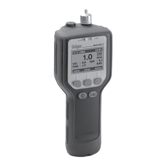
Dräger Multi-PID 2
Portable Photoionization Monitor
Instrument User manual
Software Version 3.nn
D
Tel: +44 (0)191 490 1547
Fax: +44 (0)191 477 5371
Email:
northernsales@thorneandderrick.co.uk
Website:
www.heattracing.co.uk
www.thorneanderrick.co.uk
1 0 :0 9
9 / 3 / 2 0 0
6
I N T
1 . 0
P P M
: 0 .1
T W A
: 0 .0
0 :0 5
S T E L
: 2 .9
P E A K
m e n u
c le a r
v ie w
Advertisement
Table of Contents
Troubleshooting

Related Manuals for Dräger Multi-PID 2


Summary of Contents for Dräger Multi-PID 2
- Page 1 Tel: +44 (0)191 490 1547 Fax: +44 (0)191 477 5371 Email: northernsales@thorneandderrick.co.uk Website: www.heattracing.co.uk www.thorneanderrick.co.uk Dräger Multi-PID 2 Portable Photoionization Monitor Instrument User manual Software Version 3.nn 1 0 :0 9 9 / 3 / 2 0 0 I N T 1 .
-
Page 2: Table Of Contents
Contents For Your Safety ..............................5 Notices and Warnings ............................7 FCC Warning ........................8 The Multi-PID 2 Intrinsic Safety (I/S) Notice ................ 8 ATEX Directive and EMC Directive ................... 11 WARNING ........................12 Introduction ................................. 15 About this Manual ......................16 Warnings and Safety Practices .................. - Page 3 Menu Functions ..............................53 User Interface – Basic Menu ..................... 54 Operation Modes ......................54 Unit Setup Menu ....................... 55 Memory slots Menu ......................65 Data Log Options Menu ....................68 Clear values Menu ......................70 Edit Alarms Menu ......................70 Humidity Tube Menu ......................
- Page 4 Figures Figure 1 – Multi-PID 2 ......................18 Figure 2 – Multi-PID 2 Block Diagram ................. 20 Figure 3 – Photoionization Detector ..................22 Figure 4 – Battery Pack Removal and Replacement ............27 Figure 5 – Multi-PID 2 Display .................... 29 Figure 6 –...
-
Page 5: For Your Safety
The Multi-PID 2 must be inspected and serviced by trained service personnel at regular intervals. Repair of the Multi-PID 2 may only be carried out by trained service personnel. Only authentic Dräger Safety spare parts may be used for mainte- nance. - Page 6 For Your Safety Copyright Information This document contains proprietary information that is protected by copyright. All rights are reserved. No part of this publication may be reproduced in any form whatsoever or translated into any language without the prior, written permission of Dräger Safety. Trademarks Registered names, trademarks, etc.
-
Page 7: Notices And Warnings
Notices and Warnings Notices and Warnings... -
Page 8: Fcc Warning
The Multi-PID 2 Intrinsic Safety (I/S) Notice The Multi-PID 2 is classified for use in class I, division 1, groups A, B, C, D hazardous locations. T4 (135 C) rating. - Page 9 83 23 622 Ni/Cd battery pack 83 17 670 WARNING: Do not use any other accessories with the Multi-PID 2 in a hazar- dous location, danger of an explosion! Substitution of components may affect safety rating. CAUTION: To reduce the risk of fire or injury to persons, read and follow...
- Page 10 The battery pack must be disposed of properly. Check with local codes for possible special disposal instruc- tions. Do not open or mutilate the battery pack. If the Multi-PID 2 is used in a manner not specified, the protection provided by the Multi-PID 2 may be impaired.
-
Page 11: Atex Directive And Emc Directive
Notices and Warnings ATEX Directive and EMC Directive Model: Multi-PID 2 Photoionization Monitor Certified Intrinsically Safe/Securite Intrinséque. Class I, Division 1, Groups A B C and D. Maximum surface temperature 135°C T4. II 2G Model: Multi-PID 2 0158 TRL: 03ATEX21031X EEx ib IIC T4 (Ta = 0°C to +40°C) -
Page 12: Warning
The battery pack must be disposed of properly. Check with local co- des for possible special disposal instructions. 5. Do not open or mutilate the battery pack. If the Multi-PID 2 is used in a manner not specified, the protection provided by the Multi-PID 2 may be impaired. - Page 13 PID Pre-Filter Tube Benzene 81 03 511 Dräger Tube, Humidity filter 81 03 531 NiMH battery pack 83 23 622 Ni/Cd battery pack 83 17 670 Do not use any other accessories with the Multi-PID 2 in a hazardous location.
- Page 14 Notices and Warnings...
-
Page 15: Introduction
Introduction Introduction... -
Page 16: About This Manual
Some general safety information is also provided. To help you learn to use the Multi-PID 2 quickly, this manual is organi- zed by tasks beginning with: — Using the Multi-PID 2 in “Using the Multi-PID 2” on page 25.. -
Page 17: Warnings And Safety Practices
Approved Models of the Multi-PID 2 This manual provides operational information for all models of the Multi-PID 2. The Multi-PID 2 is intrinsically safe and approved for use in hazardous locations. Refer to the Notices and Warnings section of this manual for details of each approval. -
Page 18: Intended Use
The Multi-PID 2 automatically displays and can record these concen- trations. In the TVOC mode the Multi-PID 2 does not distinguish between individual compounds. The reading displayed represents the total concentration of all pho- toionizable chemicals present in the sample. - Page 19 Multi-PID 2. All information entered with the keys and stored in the Multi-PID 2’s memory is retained when the instrument is switched off. The clock and calendar continue to operate and do not need to be reset when the Multi-PID 2 is turned...
-
Page 20: General Operation
Multi-PID 2 is turned off. A pump continuously pulls the air under test through the Multi-PID 2’s PID. The Multi-PID 2 converts the concentration of photoionizable compounds in the sample into an electrical signal. The microproces-... -
Page 21: Photoionization Detector
Multi-PID 2 would display its concentration directly. The Multi-PID 2 responds more or less readily to other chemicals than it does to isobutylene. Because it has a medium sensitivity to isobuty- lene, this gas has been chosen as a reliable means of reporting an average concentration of total ionizable compounds present. -
Page 22: Figure 3 - Photoionization Detector
Introduction Lamp Power Supply Sample Out Lampholder Lamp Driver Circuit UV Lamp Microprocessor High Voltage Light Sensor Excitation Amplifier +125 Volt Detector Cell UV Lamp Sample In UV Light Measuring Electrode – M + hn Counter Electrode Ionized Molecule Sample Figure 3 –... -
Page 23: Unpacking Instrument
Introduction Unpacking Instrument Remove the Multi-PID 2 from its shipping box. The following accesso- ries are included with the Multi-PID 2: 1. Sample Probe 2. Instrument Manual 3. Multi-Tool 4. AC Adapter or AC Adapter with AC Line Cord 5. Wrist Strap 6. -
Page 24: Support Equipment And Consumables
The Multi-PID 2 may also be connected to a computer. The computer must be a Windows -based PC. Use the cable kit (Part No. 83 17 667) to connect the Multi-PID 2 to the computer. Stored datas are evaluated using the Dräger GasVision software (Part No. -
Page 25: Using The Multi-Pid 2
Using the Multi-PID 2 Using the Multi-PID 2... -
Page 26: Battery Charging
Do not remove or recharge the battery pack in a hazardous location. danger of an explosion! To remove the battery pack: 1. If the Multi-PID 2 has been turned on, turn it off by pressing the ON/OFF key for five seconds and then releasing it. NOTE:... -
Page 27: Figure 4 - Battery Pack Removal And Replacement
Using the Multi-PID 2 Charging the Battery Pack NOTE: Only use the AC adapter specified for use with the Multi-PID 2. Using another AC adapter will result in damage to the battery pack, the Multi-PID 2 or the adapter itself. - Page 28 Leaving the AC adapter connected to the Multi-PID 2 will not harm the battery or the AC adapter in any way. If the Multi-PID 2 is to be left unused for an extended period of time, leave it connected to the AC adapter so that the battery will be fully charged and ready for opera- tion.
-
Page 29: Display
Multi-PID 2 will be reported on the display. Graphic Display The Multi-PID 2 uses an 8 line graphic display. The display will always be used for reporting detected concentration. In order to accommo- date the range of concentrations the Multi-PID 2 can detect, the meter reading will be reported using one of two resolutions. -
Page 30: Multi-Pid 2 User Menu
Using the Multi-PID 2 Multi-PID 2 User Menu menu menu Unit Setup Unit Setup Switch to GAS mode Switch to TVOC mode Data Log Options Memory slots back select back select GAS mode Unit Setup Logging Off User Mode Switch to TVOC mode... -
Page 31: Figure 7 - User Menu, Tvoc Mode
Using the Multi-PID 2 menu menu Unit Setup Unit Setup Switch to GAS mode Switch to TVOC mode Memory slots Data Log Options back select back select TVOC mode Unit Setup Pump Backlight Switch to GAS mode Memory slots User Mode... -
Page 32: Keys
Pressing the -key will start calibration in almost any mode. -key is used to both turn power on to the Multi-PID 2 as well as the turn the power off. To turn on the Multi-PID 2, press the key. To turn the power off, press the -key and hold it down for 5 seconds, and then release it. -
Page 33: Beginning Operation
2. The Multi-PID 2 will display the instrument’s software version num- ber. Next the Multi-PID 2 will proceed to the mode display. 3. The Multi-PID 2 has an instant-on lamp. For maximum accuracy and stability, allow the Multi-PID 2 to warm-up for 10 minutes prior to calibration. Default Display The display shows the last mode the Multi-PID 2 used. -
Page 34: Figure 9 - Logging Off Mode Display
" sample " key start a new measurement. TVOC mode: The Multi-PID 2 can power up in Logging Off, Tag, or Interval mode depending on the mode that was set by the previous user. The current mode is shown in the upper right-hand corner of the display. -
Page 35: Figure 10 - Tag Mode Display
Using the Multi-PID 2 ALARM CHARGE Multi-PID 2 9/3/2006 10:56 view menu Figure 10 – TAG Mode Display ALARM CHARGE Multi-PID 2 9/3/2006 11:07 STEL : 0.0 : 0.1 PEAK : 1.0 0:27 view clear menu Figure 11 – Interval Mode Display... - Page 36 Using the Multi-PID 2 Numeric Value, Duration, Time and Date Entry In cases where the system requires the user to enter a number, dura- tion, time, or date, the following mechanism is used. The number of digits to be entered depends on the type of value being entered.
-
Page 37: Table 1 - System Alerts
In addition to the status, the Multi-PID 2 also has an audio alarm and an alarm LED. To conserve power, the Multi-PID 2 alternates between the LED and audio. - Page 38 “ accept ” key. Once acknowledged, the alarm indi- cators are cleared. The alarm status will remain until the alarm condi- tion clears. The Multi-PID 2 updates the instantaneous concentration once every second. Following every update, the instantaneous concentration is compared to the REAL alarm level, and if exceeded, an alarm is triggered.
- Page 39 REAL Mode The REAL mode displays the current detected concentration. The rea- ding is updated once a second. In the background, the Multi-PID 2 datalogger is sampling the concentration and measuring minimum, maximum, and average concentrations for the selected averaging interval.
-
Page 40: Preparing For Field Operation
Using the Multi-PID 2 Preparing for Field Operation Field Check List When using the Multi-PID 2 for field operation, the following items should be carried into the field to reduce or eliminate down time of the instrument. If you are going to be in the field for a single 8-10 hour day, then you should include the following accessories: Table 2 –... - Page 41 Switch off the device. Contact DrägerService. 3. After calibration is complete, sample the calibration gas and the bag of zero air to ensure the Multi-PID 2 has been calibrated cor- rectly. 4. Select the correct operating mode. See Section regarding Opera-...
- Page 42 Using the Multi-PID 2...
-
Page 43: Connecting Accessories
Connecting Accessories Connecting Accessories... -
Page 44: Computer
PC. Once the Dräger GasVision software is running, the PC is rea- dy to receive data from the Multi-PID 2. 5. On the Multi-PID 2, the number of data bits has been fixed at 8, stop bits has been fixed at 1. Parity has been set at None and the Flow control is Xon/Xoff. -
Page 45: Pre-Filter Tube Holder
Connecting Accessories 6. On the Multi-PID 2, press the " menu " key, choose » Data Log Options «, then press the " select " key. 7. Choose the » Download to PC « option using the " " key and press the "... -
Page 46: Pre-Filters And Sample Collection Tubes
Pre-filters and Sample Collection Tubes Dräger Safety provides a variety of pre-filter tubes for the Multi-PID 2. The tubes are custom developed for Dräger Safety AG & Co., and address clean air calibration and humidity reduction to facilitate more accurate sampling. -
Page 47: Wrist Strap
Adjust the strap length as necessary. DC Power Cord The Multi-PID 2 can be connected to a car battery through the ciga- rette lighter with the DC power cord. While the Multi-PID 2 is connec- ted to the car battery, the Multi-PID 2 battery is being charged. -
Page 48: 11.7 Ev Uv Lamp
Connecting Accessories 11.7 eV UV Lamp General Information The Multi-PID 2 is equipped with a standard 10.6 eV UV lamp. An 11.7 eV UV lamp (Part No. 83 18 317) is available for special applica- tions. Install this lamp as outlined in Removing and Replacing the UV Lamp on page 80. - Page 49 Connecting Accessories To use the 11.7 eV lamp in your the Multi-PID 2: 1. Remove the 11.7 eV lamp from the supplied desiccant bottle and install the lamp as outlined in Removing and Replacing the UV Lamp on page 80.
-
Page 50: Off-Line Charger
Part No. 83 17 661 (Europe) DC Power Cord Part No. 64 05 421 Use only the AC adapter specified for use with the Multi-PID 2. Using another AC adapter will result in damage to the battery pack, the off- line charger, or the adapter. - Page 51 9. Remove the battery pack connector from the socket on the off-line charger. 10. Replace the battery pack in the Multi-PID 2 as outlined in Remo- ving and Replacing the Battery Pack on page 26. You can keep the battery pack fully charged indefinitely, without over- charging it, by leaving it connected to the off-line charger while the charger is operating.
- Page 52 Connecting Accessories...
-
Page 53: Menu Functions
Menu Functions Menu Functions... -
Page 54: User Interface - Basic Menu
Menu Functions User Interface – Basic Menu The Multi-PID 2 is designed for ease of use with a logically organized internal menu structure/user interface. The Multi-PID 2 User Menu is shown in Figures 6 and 7 on page 30 and page 31. -
Page 55: Unit Setup Menu
Unit setup functions are used to select the Multi-PID 2 features. There are nine functions which can be set on the Multi-PID 2; » Pump «, » Backlight «, » User Mode «, » Clock «, » Date format «, »... -
Page 56: Figure 14 - Unit Setup Map
Menu Functions GAS mode Unit Setup Logging Off User Mode Sample Units Clock Date format Backlight Language Enter current time – Passcode Enter current date MM/DD/YYYY DD/MM/YYYY English German Change Passcode or lock / unlock instrument TVOC mode Unit Setup Pump Backlight User Mode... - Page 57 0.0. Turn the pump and detector off when concentration measurements are not necessary, and the Multi-PID 2 will only be used for setup or reviewing data. By operating the instrument with the pump and detec- tor off when you do not need them, you will conserve the battery and ultraviolet (UV) lamp.
- Page 58 2. Select " Logging Off ", then press " select " In this mode, the only soft key displayed is the " menu " key. " menu " selects the Multi-PID 2’s internal menu for the Multi-PID 2 setup by the user.
- Page 59 These recorded data can now be reviewed and edited. Recorded data can also be printed using the PC. For each averaging interval, the Multi-PID 2 prints the minimum of all the minima, the average of all the readings for the interval and the maximum of all the maxima.
- Page 60 STEL is set to zero each time the instru- ment is turned on. STEL calculations are always being performed by the Multi-PID 2. You can display the results of the calculations by selecting STEL as the Display mode.
-
Page 61: Figure 15 - Intervall Time Adjustment
1000 15 m 3000 The Multi-PID 2’s display can show four values in Interval mode: STEL, TWA, and REAL, plus the instantaneous reading. Activating " Interval " mode: 1. Press the " menu " key and select " Unit Setup ", then press "... -
Page 62: Figure 16 - Setting The Time
" key to select one of the selection options, then press " clear " to delete the stored data of the corresponding option. " menu " selects the Multi-PID 2’s internal menu for the Multi-PID 2 setup by the user. - Page 63 Press the " done " soft key to confirm the time and move to the date option. 6. When setting the date, the Multi-PID 2 prompts you for the current date formatted as Month/Day/Year. Use the " " "...
- Page 64 The " Passcode " function can be used to change the passcode as well as to activate or de-activate the menu function block. The " lock " function is used to prevent access to the Multi-PID 2’s sensitive options. Sensitive options are those which can affect the Multi-PID 2’s readings.
-
Page 65: Memory Slots Menu
Multi-PID 2 was calibrated using that specific single compound. In situations where only a single pure compound is present in air, the Multi-PID 2 should be calibrated with a standard of that specific com- pound as span gas. - Page 66 The Multi-PID 2’s 15 memory slots can be used to store calibration information for 15 different span gases. The Multi-PID 2 will always detect all ionizable compounds present in a sample regardless of the response factor (RF) selected.
-
Page 67: Figure 17 - Function Memory Slots Settings
“ done “ Figure 17 – Function Memory Slots Settings Response factors built into the Multi-PID 2 are used to correct for the response of the PID to a specific compound. These correction factors are often called response factors (RF). The Multi-PID 2 has 15 memory slots. -
Page 68: Data Log Options Menu
" select " to edit another value. 8. To return to the main menu, press " select ", then " done ". To select a pre-programmed compound stored in the Multi-PID 2’s Preset RRF library: 1. Press " menu ", then use the "... - Page 69 The " Download to PC " function starts the download of data from the Multi-PID 2 onto the PC. The Multi-PID 2 computer cable, Part No. 83 17 667, must be connected between the Multi-PID 2 and the PC before beginning the data download. The Dräger GasVision software must be installed and running on the PC prior to download.
-
Page 70: Clear Values Menu
Menu Functions Clear values Menu Only available in GAS mode. The " Clear values " function can be used to clear the latest measure- ment values for the highest measured concentration (SMAX), the lat- est STEL value or all values (ALL) which are shown in the display. 1. -
Page 71: Routine Maintenance
Routine Maintenance Routine Maintenance... -
Page 72: Maintenance Intervals
(zero) signal is generated. This zero signal is stored by the micropro- cessor. The Multi-PID 2 is next exposed to span gas. This span gas signal is stored by the microprocessor. The microprocessor subtracts the zero signal from the span gas signal and divides the difference by the user- entered span gas concentration. -
Page 73: Calibration Introduction
Routine Maintenance Calibration Introduction The Multi-PID 2 must be calibrated in order to display concentration in ppm units equivalent to the calibration gas. First, a supply of zero air, which contains no ionizable gases or vapors, is used to set the Multi-PID 2’s zero point. - Page 74 Routine Maintenance Compressed Gases Cylinders of compressed gas, such as calibration gas, must be hand- led with extreme care. For safety, the calibration gas cylinders must be secured before use. Please observe the following handling procedures: Mark each new regulator with its intended gas service and never use a regulator for more than one service.
- Page 75 Adjust the delivery pressure and then open the regulator outlet valve. Calibration Gas Adequate ventilation must be provided when the Multi-PID 2 is being calibrated. If compound threshold limit values (TLV) are exceeded, you should use a gas bag for sampling and calibration.
-
Page 76: Calibration Using The Flow-Match Regulator
4. Connect the adapter tubing to the regulator. 5. Check if the Multi-PID 2 is sucking in the gas pressure free, e.g. by means of a T-piece; paying attention the fact that the flow from the gas cylinder is higher than the inlet flow of the Multi-PID 2. - Page 77 (Part No. CH 24 101) and filter tube holder (Part No. 83 19 093), or leave the instrument unconnected so it can sample clean ambi- ent air. Then press the “ next ” key. The Multi-PID 2 will take 60-90 seconds to set the zero point for calibration.
-
Page 78: Battery Charging
The Multi-PID 2 is not intrinsically safe when con- nected to an AC adapter. When the Charge LED on the top of the Multi-PID 2 is red, the battery is charging. When the Charge LED turns green, the battery is fully... - Page 79 If the Multi-PID 2 is not used for long periods of time, recharge the battery for a few hours every 30 days to avoid loss of data. See Battery Charging on page 26 for instructions on charging the battery.
-
Page 80: Maintenance Of The Uv Lamp
You must turn the instrument off before removing the lamp cover. 2. Remove the lamp housing cover. 3. Tilt the Multi-PID 2 slightly and remove the UV lamp. WARNING: Do not touch the wire grid inside the detector cell. Any dust or dirt in the detector cell can be blown out with a gentle jet of compressed air. -
Page 81: Figure 19 - Removing The Uv Lamp
Figure 19 – Removing the UV Lamp NOTE: Do not force the lamp into the lamp holder. 5. Replace the lamp housing cover. Tighten the cover down. Do not over tighten. 6. Calibrate the Multi-PID 2 and then continue normal operation. - Page 82 Routine Maintenance Cleaning the UV Lamp Window During the course of normal operation, a film builds up on the window of the UV lamp. The rate at which the film develops depends on the type and concentration of the gases and vapors being sampled and results from the UV light interacting with them.
- Page 83 Routine Maintenance To clean the UV lamp: 1. Remove the lamp as outlined in Removing and Replacing the UV Lamp on page 80. 2. Allow the lamp to cool to room temperature to avoid thermal shock, which could crack the window. 3.
-
Page 84: Replacing The Sample Inlet Filter
PID 2 is used in a dusty or wet environment. You must replace the fil- ter if the Multi-PID 2 has been exposed to water. If you are sampling hot gases or vapors, condensation in the sample line may also affect the filter. -
Page 85: Waste Electrical And Electronic Equipment
Routine Maintenance ALARM CHARGE Multi-PID 2 Figure 20 – Replacing the Inlet Filter Waste electrical and electronic equipment EU-wide regulations for the disposal of electric and electronic appliances which have been defined in the EU Directive 2002/96/ EC and in national laws are effective from August 2005 and apply to this device. - Page 86 Routine Maintenance...
-
Page 87: Troubleshooting
Troubleshooting Troubleshooting... -
Page 88: General Information
Troubleshooting General Information If you have a service-related question about the Multi-PID 2, consult this manual first. If you cannot find the answer in this documentation, contact Dräger Safety’s Technical Support Department. When you call, please have the following information ready: 1. -
Page 89: Troubleshooting
Ambient air is contaminated. If you are not sure of the cleanliness of the ambient air, use a commercial zero grade air to zero the Multi-PID 2. Span Gas Error Span gas and zero air are Ensure that clean air is used to zero mixed up. - Page 90 PIDs are designed to detect rela- electronics. tively low levels of gases. The detector has become Move the Multi-PID 2 to a location saturated. where it can sample clean air. Sample clean air until the readings stabilize at a low level.
-
Page 91: General Questions
Troubleshooting General Questions Fault Possible Cause Remedy Very low or no instrument The Multi-PID 2 has not been Verify the concentration of response detected, yet com- properl the span gas. Calibrate the pounds are known to be pre- Multi-PID 2. See page 73. - Page 92 The water vapor becomes an electrolytic solu- tion which becomes ionized when it enters the detector. The Multi-PID 2 is not pro- Ensure that the calibration perly calibrated. gas is the correct concentra- tion and calibrate the Multi-...
-
Page 93: Appendices
Appendices Appendices... -
Page 94: Specification
Appendices Specification Size: 9” (230 mm) long x 3” (80 mm) deep x 4.25” (110 mm) wide at display tapering to 2.6” (67 mm) at handle Weight: 1.9 pounds (0.86 kg) Detector: Instant on photoionization detector with standard 10.6eV UV lamp, optional 11.7 eV lamp available Keypad: 5 keys with tactile feedback... - Page 95 Appendices ® Materials in sample stream: Stainless steel, Teflon, Viton , polypropy- lene, nitrile-chorobutadiene rubber, nickel. Inlet filter: Replaceable Teflon/Polypropylene, 1 μm Inlet flow rate: Greater than 300 mL/min Operating temperature range: 0 to 50 C (32 to 122 I/S Certified Temperature Range: 0 to 40 C (32 to 105 Operating humidity range:...
-
Page 96: Installing Alternate Ac Plug On The Battery Charger
Appendices Installing Alternate AC Plug on the Battery Charger In most cases the Multi-PID 2 will be shipped with an AC line cord that will fit the AC wall outlet in your area. If this cannot be done, you may need to obtain an AC line cord suitable for the AC receptacle in your area. -
Page 97: Presets And Response Factors
The following formula is used for calculation of response factors: Actual Concentration Response Factor Multi-PID 2 Response A response factor less than 1.0 indicates a compound response bet- ter than that of isobutylene. A response factor greater than 1.0 indica- tes a lower response than that of isobutylene. - Page 98 Appendices Compound Response Factor n-Butyl Acetate Butyl Acrylate Butyl Cellosolve n-Butyl Acrylate n-Butyl Mercaptan (Butanthiol) Carbon Disulfide Chlorobenzene Crotonaldehyde (2-Butenal) Cumene (Isopropylbenzene) Cyclohexane Cyclohexanol Cyclohexanone Diacetone alcohol 1,2-Dichlorobenzene (ortho-) cis-1,2-Dichloroethylene trans-1,2-Dichloroethylene N,N-Dimethylformamide (DMF) 1,4-Dioxane Epichlorohydrin Ethanol Ethyl Acetate Ethyl Acrylate Ethylbenzene Ethyl Cellosolve (2-Ethoxyethanol) Ethylene Glykol...
- Page 99 Appendices Compound Response Factor Isoamyl Acetate Isobutyl Acetate Isobutyl Alcohol Isobutyraldehyde Isopentane Isoprene (2-Methyl-1,3-Butadiene) Isopropanol Isopropyl Acetate Isopropyl Ether Mercaptopropionic Acid Methacrylic Acid Methyl n-Amyl Ketone (2-heptanone) Methyl Bromide (Bromomethane) Methyl Chloroform (1,1,1 – TCA) Methylene Chloride Methyl Ethyl Ketone (2-Butanone) Methyl Isobutyl Ketone Methyl Mercaptan Methyl Methacrylate...
-
Page 100: Table 6 - Library Entries
Appendices Compound Response Factor Syltherm XLT Tetrachloroethylene (Perchloroethylene) Tetrahydrofuran Therminol Toluene 1,1,1 – Trichloroethane Triethanolamine Trichloroethylene (TCE) Trimethylamine 1,2,4 – Trimethyl Benzene 1.3.5 – Trimethyl Benzen Vinyl Acetate Vinyl Bromide Vinyl Chloride (Chloroethylene) Vinylidene Chloride (1,1-DCE) meta –Xylene ortho –Xylene para-Xylene Table 6 –... - Page 101 Appendices Compound Code n-Butyl Acetate nBUTACET n-Butyl Acrylate nBUTACRY n-Butyl Mercaptan (Butanethiol) nBUTMERC Carbon Disulfide Chlorobenzene CHLOBENZ Crotonaldehyde (2-Butenal) CROTONAL Cumene (Isopropylbenzene) CUMENE Cyclohexane CYCHEXAN Cyclohexanone CYCHEXON 1,2-Dichlorobenzene (ortho-) 12DCBENZ cis-1,2-Dichloroethylene cis12DCE trans-1,2-Dichloroethylene trn12DCE N,N-Dimethylformamide (DMF) N,N-DMF 1,4-Dioxane DIOXANE Epichlorohydrin EPICLHYD Ethanol ETHANOL...
- Page 102 Appendices Compound Code Isopropyl Acetate IPACETAT Isopropyl Ether IPROPETH Methyl Bromide (Bromomethane) MeBROM Methyl Ethyl Ketone Methyl Isobutyl Ketone MIBK Methyl Mercaptan (Methanethiol) METHMERC Methyl Methacrylate MeMeACRY Methyl tert-Butyl Ether (MTBE) MTBE Monomethylamine MMeAMINE n-Nonane nNONANE Iso-Octane (2,2,4-Trimethylpentane) IOCTANE n-Pentane nPENTANE 10.4 n-Propanol...
-
Page 103: Reference
2 In those cases where no STEL exists for a compound, the STEL value has been established as equivalent to the TWA value 3 Compound is Not Detectable (ND) by the Multi-PID 2. Please contact Dräger Safety Applications Department for further details. - Page 104 Appendices...
- Page 105 Index AC adapter ............. . 27 Accessories .
- Page 106 Fixed Keys ..............32 GAS mode Display .
- Page 107 Turning the Multi-PID 2 On ........
Need help?
Do you have a question about the Multi-PID 2 and is the answer not in the manual?
Questions and answers