Table of Contents
Advertisement
Advertisement
Table of Contents

Related Manuals for Dräger Polytron 5200


Summary of Contents for Dräger Polytron 5200
- Page 1 Dräger Polytron 5200/53X0 Instructions for Use WARNING Strictly follow the Instructions for Use. The user must fully understand and strictly observe the instructions. Use the product only for the purposes specified in the Intended use section of this document.
- Page 2 www.norrscope.com...
-
Page 3: Table Of Contents
-0- adj ........16 9.2.1 Polytron 5200 DD remote e ....27 3.7.2 Spn adj . -
Page 4: For Your Safety
The instruments or components may not be modified in any manner. The use of faulty or incomplete parts is forbidden. The appropriate regulations must be observed at all times when carrying out repairs on these instruments or compo- nents. Dräger Polytron 5200 / Dräger Polytron 53X0... -
Page 5: Description
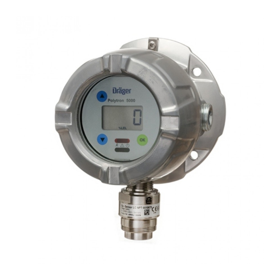
4 Enclosure bottom 2 Bezel with main 5 Sensor electronics 6 Feed-through 3 Relay board (optional) 7 Field wire terminals 4 Enclosure bottom (not shown) 5 Sensor 8 e-box 6 Assembled instrument 9 Assembled instrument Dräger Polytron 5200 / Dräger Polytron 53X0... -
Page 6: Intended Use
Dräger WARNING Explosive. Not to be used in oxygen enriched atmo- spheres. None of the Polytron 5000 instruments are certified and approved to be operated in oxygen enriched atmospheres. Dräger Polytron 5200 / Dräger Polytron 53X0... -
Page 7: Operation
55 °C, use only appropriate wiring, specified meant to be watertight, and must be removed before for at least 25 °C above the maximum ambient connecting the instrument to a sealed conduit. temperature. Strip wire insulation by 5-7 mm. Dräger Polytron 5200 / Dräger Polytron 53X0... -
Page 8: Electrical Installation Without E-Box
Mark none in a difficult to reach or awkward position, see Polytron 5000 Junction Box Instructions for Use 4544286 for more details. 4-20 mA Function signal Dräger Polytron 5200 / Dräger Polytron 53X0... -
Page 9: Electrical Installation With E-Box
The method of explosion protection during mainte- nance is based on the condition that it is not possible to contact bare cable parts by a probe of 2.5 mm diam- eter (definition of IP 30). Dräger Polytron 5200 / Dräger Polytron 53X0... -
Page 10: Field Wiring: Power And Relay, Or Power, Relay And Remote Sensor Version
Sensing Head DrägerSensor IR complete Set e 6811265 Sensing Head Dräger PIR 3000 complete Set e 6811160 ----- ----- Brown Black Sensing Head Dräger PIR 3000 complete Set e 6811270 1) not yet available Dräger Polytron 5200 / Dräger Polytron 53X0... -
Page 11: Attaching Main Instrument To E-Box
Align the boss of the instru- ment with the boss of the e-box and push the hinge pin back in. The instrument is now supported and can swivel freely to give access to the wiring. 1 Hinge pin Dräger Polytron 5200 / Dräger Polytron 53X0... -
Page 12: Instrument Wiring
After all connections are made, swing instrument onto e-box (ensuring that no wires are pinched and the seal is not compro- mised) and tighten all four screws with correct torque see Section 8.5 on Page 24 Dräger Polytron 5200 / Dräger Polytron 53X0... -
Page 13: Connecting The Instrument To A Controller From Dräger
In normal operation, the display shows the measured gas con- centration and unit of measurement. The green LED is lit. The following special symbols may also be displayed: when the measuring range of the sensor has been exceeded Dräger Polytron 5200 / Dräger Polytron 53X0... -
Page 14: Menu Navigation
Use the Up and Down arrows to increment or decrement this digit, then tap OK. The second digit will blink; set the correct value using the Up and Down arrows. Repeat the process for the other two digits. Dräger Polytron 5200 / Dräger Polytron 53X0... -
Page 15: Menu
Operation Menu 1 Only for relay version 2 Only for DSIR Dräger Polytron 5200 / Dräger Polytron 53X0... -
Page 16: 0- Adj
Configuring whether the alarm should be triggered by a rising or falling gas concentration. 3.7.7 A2 ris or A2 fall Configuring whether the alarm should be triggered by a rising or falling gas concentration. Dräger Polytron 5200 / Dräger Polytron 53X0... -
Page 17: A1 Lat
The actual selection is made at the DSIR. While in this menu, the Polytron 5000 will display gas category as it is output from the DSIR. See Instructions for Use for DrägerSensor IR. Dräger Polytron 5200 / Dräger Polytron 53X0... -
Page 18: Cal At Dsir
After changing the selected sensor, the instrument will re-start. When exchanging a sensor for a different type, the in- strument must be calibrated. Dräger Polytron 5200 / Dräger Polytron 53X0... -
Page 19: Maintenance
4. Use the Up / Down arrow to adjust the value to 50. 5. Acknowledge with OK; the display will then jump back to the main menu. 6. Turn off the gas flow and remove the calibration adapter from the sensor, or disconnect tubing. Dräger Polytron 5200 / Dräger Polytron 53X0... -
Page 20: Troubleshooting
Call Dräger Service more than 1 minute Err 198 Memory error Call Dräger Service Err 199 Factory calibration required Call Dräger Service Warnings Info 301 Sensor is warming up Wait for warm-up phase to end Dräger Polytron 5200 / Dräger Polytron 53X0... -
Page 21: Replacing The Sensor
10. Screw the lid back on, until it is seated, and tighten set- screw. 11. Apply power to the instrument. 12. Calibrate instrument, see Section 4.1 on Page 19. 13. Always test a newly-installed sensor with target gas to verify proper operation. Dräger Polytron 5200 / Dräger Polytron 53X0... -
Page 22: Default Settings
A1 and A2: Acknowledging will cause the A1 relay to release. However, the red LED will still double blink as long as the A2 condition continues to exist. Dräger Polytron 5200 / Dräger Polytron 53X0... -
Page 23: Sensor Principle
Internal electronics and software are used to calculate the con- centration. As an output signal, the gas sensor emulates the half bridge of a catalytic bead sensor. Dräger Polytron 5200 / Dräger Polytron 53X0... -
Page 24: Technical Data
20 mA to 20.5 mA Measuring range exceeded > 21 mA Fault on the analog output 3.4 mA steady or 1 Hz modulation between Signal for maintenance mode 3 and 5 mA (user selectable) Dräger Polytron 5200 / Dräger Polytron 53X0... -
Page 25: Physical Specifications
(-40 to 70 °C) -40 to 149 °F -40 to 149 °F DSIR / PIR 3000 (-40 to 65 °C) (-40 to 65 °C) not yet available Ambient influences See sensor data sheets. Dräger Polytron 5200 / Dräger Polytron 53X0... -
Page 26: Order List
Polytron 5310 e S Relay 4544379 Polytron 5200 Remote DD e A 4544156 Polytron 5310 Remote e S 4544380 Polytron 5200 Remote DD e A Relay 4544157 Polytron 5310 Remote e S Relay 4544381 Polytron 5200 DD e S 4544158... -
Page 27: Separate Sensing Head (Not Included) When Ordering
6811135 1) not yet available Spare parts Replacement sensors Part Number Description (all versions except remote e) Bezel Polytron 5200 / 53X0 / 57X0 4544183 Part Number Description PCB Main Polytron 5200 / 53X0 4544186 DrägerSensor Ex DD NPT 6812380... - Page 28 www.norrscope.com...
- Page 29 www.norrscope.com...
- Page 30 www.norrscope.com...
- Page 31 www.norrscope.com...
Need help?
Do you have a question about the Polytron 5200 and is the answer not in the manual?
Questions and answers