Table of Contents
Advertisement
Quick Links
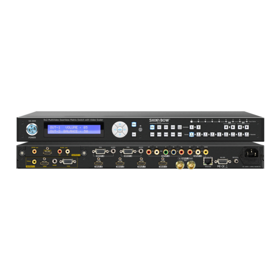
SB-3888
9x2 MultiVideo To HDMI/VGA Matrix Selector Switch Scaler
IMPORTANT WARRANTY INFORMATION.
If you remove the HDMI screw posts, you must use the provided HDMI Locking Post replacement
screws to keep the internal HDMI jack secure. Removing the HDMI screws without installing
the HDMI Locking Post replacement screws will void your warranty.
Advertisement
Table of Contents

Subscribe to Our Youtube Channel
Related Manuals for Shinybow USA SB-3888


Summary of Contents for Shinybow USA SB-3888
- Page 1 SB-3888 9x2 MultiVideo To HDMI/VGA Matrix Selector Switch Scaler IMPORTANT WARRANTY INFORMATION. If you remove the HDMI screw posts, you must use the provided HDMI Locking Post replacement screws to keep the internal HDMI jack secure. Removing the HDMI screws without installing...
-
Page 2: Safety Information
SAFETY INFORMATION To ensure the best results from this product, please read this manual and all other documentation before operating your equipment. Retain all documentation for future reference. Follow all instructions printed on unit chassis for proper operation. To reduce the risk of fire, do not spill water or other liquids into or on the unit, or operate the unit while standing in liquid. Make sure power outlets conform to the power requirements listed on the back of the unit. -
Page 3: Table Of Contents
MultiVideo To HDMI-VGA Matrix Selector Switch Scaler Series Thank you for purchasing the SB-3888 9x2 MultiVideo to HDMI/VGA Matrix Selector Switch Scaler. You will find this unit easy to install and highly reliable but it is essential that you read this manual thoroughly before attempting to use this... -
Page 4: Features & Contents
• Power supply Universal Type switch 100~240VAC, 50/60Hz PACKAGE CONTENTS Check that you have the following components; • SB-3888 Selector Switch Scaler • RS-232 V1.0/Ethernet V1.0 Protocol Instructions • Master wireless IR Remote Control (SW-3888) • 19 inch Ear mount bracket (Part # 1U-440L) •... -
Page 5: Specifications
SPECIFICATIONS SPECIFICATIONS • Type of Switcher: 9x2 Seamless MultiVideo to HDMI-VGA-Video Matrix PiP-PoP Selector Switch Scaler • Function Modes: Matrix, PiP & PoP • HDMI Supported: HDMI 1080p@60Hz, H36-bit Deep color • HDCP / HDMI Supported: HDCP 1.2 Compliant, HDMI 1.3 version • Video Bandwidth: Double Data Rates: 165Mhz, Total 4.95Gbps bandwidth • Scaling Video Supported: HD: 480i/ 480p/ 720p and up to 1080i/p NOTE: Supports SDI in/out 1080p-30Hz • (9) Source Inputs: (1) Composite Video/Stereo Audio, (1) Component Video/Stereo Audio, (2) VGA/Stereo Audio, (1) SDI, (4) HDMI... -
Page 6: Front Panel
FRONT PANEL FRONT PANEL 1. POWER SWITCH: The power switch turns the unit on and off. The LED will illuminate blue to indicate that the switcher is ON and is receiving power. The switcher will remember that last state during a power cycle. When power is removed and resorted, the last configuration will be evoked. -
Page 7: Function Keys
FUNCTION KEY - MATRIX FUNCTION KEY 10. FUNCTION KEY: MATRIX (9:2) To enable the MATRIX SWITCH option on a specific Destination, perform the following steps: 1. Press OUTPUT 1 THRU 2 button on the DESTINATION row (the button will illuminate momentarily). 2. - Page 8 FUNCTION KEY - PiP 11. FUNCTION KEY: PiP: To enable the PiP option on a specific Destination perform the following steps: 1. Press OUTPUT 1 THRU 2 button on the DESTINATION row, for PiP mode (the button will illuminate momentarily). 2.
- Page 9 FUNCTION KEY - PoP 11. FUNCTION KEY: PoP: To enable the PoP option on a specific Destination, perform the following steps: 1. Press OUTPUT 1 THRU 2 button on the DESTINATION row, for PoP mode (the button will illuminate momentarily). 2.
- Page 10 FUNCTION KEY - ZOOM / SWAP 13. FUNCTION KEY: ZOOM: SETUP ZOOM MODE FROM PIP. To enable ZOOM mode on PiP for a specific Output, perform the following steps: 1. In the system setup for the PiP mode, the PiP position will move around the corners of the screen. 2.
- Page 11 FUNCTION KEY - MEMORY 15. FUNCTION KEY: MEMORY: MEMORY mode to MEMORY Destination 1 or 2 when Matrix, PiP or PoP status. The system will show stored presets up to a total of (9) in each Output-1 or 2. Presets are stored in local memory using Source keys 1 THRU 9 as the memory preset location.
- Page 12 FUNCTION KEY - RECALL 16. FUNCTION KEY: RECALL: RECALL the memory shown previously in stored presets. The system will show previously stored presets, up to a total of (9). Preset are stored in local memory using the A/V source keys 1 THRU 9 as the memory preset locations.
- Page 13 FUNCTION KEY - AUDIO BREAKAWAY 17. FUNCTION KEY: AUDIO BREAKAWAY: AUDIO BREAKAWAY Mode to separate Video and Audio. The LCM will not show OUTPUT-2 on the display when the Modular Output-2 port is removed. Using the AUDIO BREAKAWAY the system will separate the Video and Audio output. 1.
- Page 14 FUNCTION KEY - MUTE / EXIT / LOCK 18. FUNCTION KEY: MUTE: Audio MUTE Mode to mute audio. The LCM will not show OUTPUT-2 on the display when Modular Output-2 port is removed. 1. Press the MUTE button once. The MUTE button LED will illuminate when MUTE is turned on. 2.
- Page 15 FUNCTION KEY - MENU 20. FUNCTION KEY: MENU MENU mode to adjust or set the Output-1 or Output-2 function status. MENU Function Modes: Setup the embedded EDID mode, Output Resolutions, Audio Volume, Audio Balance(R/L), Audio EQ, TV Video System standard, Over IP or Coax Channels. Presets are stored in local Audio EQ using the MENU button. Configure desired matrices.
- Page 16 FUNCTION KEY - MENU [EDID] 21. FUNCTION KEY: MENU [EDID] OUTPUT-1 & OUTPUT-2 EDID Learning mode M2 setup The LCM will not show OUTPUT-2 on the display when the Modular Output-2 port is removed. To enable the Learning EDID mode option on a specific Output, perform the following steps: 1.
- Page 17 FUNCTION KEY - MENU [RESOLUTION] 22. FUNCTION KEY: MENU [RESOLUTION] OUTPUT-1 & OUTPUT-2 Resolution Setup The LCM will not show OUTPUT-2 on the display when the Modular Output-2 port is removed. To enable the Learning EDID mode option on a specific Output, perform the following steps: 1.
- Page 18 FUNCTION KEY - MENU [AUDIO BALANCE] 23. FUNCTION KEY: MENU [AUDIO BALANCE] AUDIO BALANCE mode to control Audio Balance (R/L). The LCM will not show OUTPUT-2 on the display when the Modular Output-2 port is removed. To enable the Learning EDID mode option on a specific Output, perform the following steps: 1.
- Page 19 FUNCTION KEY - MENU [AUDIO EQUALIZER] 24. FUNCTION KEY: MENU [AUDIO EQUALIZER] AUDIO EQUALIZER mode to control the Audio Equalizer. The LCM will not show OUTPUT-2 on the display when the Modular Output-2 port is removed. To enable the Learning EDID mode option on a specific Output, perform the following steps: 1.
- Page 20 FUNCTION KEY - MENU [TV VIDEO SYSTEM STANDARD] 25. FUNCTION KEY: MENU [TV VIDEO SYSTEM STANDARD] TV VIDEO SYSTEM mode to control output TV output system standard. The LCM will not show OUTPUT-2 on the display when the Modular Output-2 port is removed. To enable the Learning EDID mode option on a specific Output, perform the following steps: 1.
- Page 21 FUNCTION KEY - MENU [RESET] 26. FUNCTION KEY: MENU [RESET] FOR RETURN TO FACTORY DEFAULT. The LCM display will show the SYSTEM RESET status. The system will return to factory default. To setup the switcher for the SYSTEM RESET command, perform the following steps: 1.
- Page 22 FUNCTION KEY - MENU [IP CHANNEL] 27. FUNCTION KEY: MENU [IP CHANNEL] IP CHANNEL mode setup the IP Transmitter output. The LCM will not show OUTPUT-2 on the display when the Modular Output-2 port is removed. To enable the IP CHANNEL mode option on a specific Output, perform the following steps: 1.
- Page 23 FUNCTION KEY - MENU [COAX DTV CHANNEL] 28. FUNCTION KEY: MENU [COAX DTV CHANNEL] To setup the COAX DTV CHANNEL mode via COAX cable output. The LCM will not show OUTPUT-2 on the display when the Modular Output-2 port is removed. To enable the DTV Channel mode option on a specific Output, perform the following steps: 1.
- Page 24 FUNCTION KEY - MENU [COAX CHANNEL] 29. FUNCTION KEY: MENU [COAX CHANNEL] To setup the COAX CHANNEL mode via COAX cable output. The LCM will not show OUTPUT-2 on the display when the Modular Output-2 port is removed. To enable the COAX CHANNEL mode option on a specific Output, perform the following steps: 1.
-
Page 25: Back Panel
BACK PANEL BACK PANEL 1. POWER INLET: POWER SOCKET : The switcher is fitted with an AC power plug input Connector Type : IEC 60320 C13 connector. Ensure that the plug used is of an approved type and is of sufficient current carrying connector capacity with the correct voltage and connector polarity. - Page 26 BACK PANEL BACK PANEL 6. VIDEO/AUDIO INPUT: Video (Composite) (1) RCA female connector Connects a Video/Audio (Composite video) Audio (Stereo Audio) (2) RCA female connectors signal source to the Composite Video connector. Note: With (3) RCA female connectors. 7. COMPONENT VIDEO/AUDIO INPUT: Component Video (YPBPR) (1) RCA connector Connects a Component Video- Audio (Stereo Audio) (2) RCA female connectors...
- Page 27 OPTIONAL MODULAR OUTPUT CARDS OPTIONAL MODULAR TABLE : 3888 MODULAR: SCALER OUTPUT 2 MODEL: T-HDMI-A: HDMI BOOSTER WITH AUDIO OUTPUT (INCLUDED) (1) HDMI OUT, (1) STEREO AUDIO & (1) SPDIF OUT MODEL: T-HDBT-100: HDMI OVER HDBASET OUTPUT ™ (1) HDBT OUT (100M), (1) IR IN/OUT & RS-232 MODEL: T-HDBT-100P: HDMI OVER HDBASET OUTPUT W/ POH ™...
-
Page 28: Remote Control
REMOTE CONTROL & REMOTE PROTOCOL COMMANDS BEFORE MAKING ANY CONNECTIONS OBSERVE THE FOLLOWING: • Ensure the main voltage supply matches the label on the supplied plug-pack (+/-10%). • Ensure that the power switch is OFF. • Ensure that all system grounds (earth) are connected to a common point. •... - Page 29 IR DATA CODE LIST IR REMOTE CUSTOM AND DATA CODES (NEC Standard) HOW TO SETUP IR CODES : CUSTOM CODE : 6798 POWER ON: 6798 A15E AUDIO: 6798 BA45 POWER OFF: 6798 A25D 1-VOLUME+: 6798 8D72 MUTE: 6798 9E61 2-VOLUME+: 6798 DB42 ZOOM:...
-
Page 30: Rs-232 & Ethernet Protocol
RS-232 & ETHERNET SERIAL INTERFACE RS-232 & ETHERNET SERIAL INTERFACE CONNECT a PC or CONTROL SYSTEM. VERSION COMPATIBLE V1.0 For a complete list of commands, please reference external document extended RS-232 Protocol Instruction Manual. Example of the command string to select Inputs: FUNCTION COMMAND COMMAND VARIABLES... -
Page 31: Typical Hook-Up & Application
TYPICAL APPLICATION INSTALLING DIAGRAM Sample Connection: 1. Using the IR External, RS-232 series interface or Ethernet place the command to control the SB-3888 via PC or the IR external receiver (model SB-100) to transmit the SB-3888’s IR remote signal. NOTE: 1. - Page 32 TYPICAL APPLICATION INSTALLING DIAGRAM Sample Connection: Using (9) A/V sources input and scaling up to (2) HD resolutions matrix outputs. NOTE: (9) Inputs (1) Composite Video/Stereo Audio. (1) Component Video/Stereo Audio. (2) VGA/Stereo Audio. (1) SDI. (4) HDMI Full HD sources. Applications (9) A/V sources inputs matrix to (2) HD resolution outputs.
- Page 33 TYPICAL APPLICATION INSTALLING DIAGRAM Sample Connection: OUTPUT-1. Using Composite Video, VGA, HDMI and Stereo signal connected to a HDTV. OUTPUT-2. Using Modular type output HDMI, SPDIF and Stereo Audio signal connected to a HDTV. OUTPUT-1 NOTE: 1. Video TV: Composite Video/Audio. 2.
-
Page 34: Ir Extender
IR EXTENDER IR EXTENDER 1. SB-100 IR 300M Receiver Switcher IR EXT. In Cable (3C) IR Receiver (SB-100) Distance: Max.300M IR PN#: SB-XXXX R oHS /95/E C INP UT R S -232 IR E XT. in DC 12V IR Rx RS - 232 IR EXT . -
Page 35: Input & Output Resolutions
INPUT & OUTPUT RESOLUTIONS HDMI INPUT RESOLUTIONS 480i 576i 720p 1080p 480p 576p 1080i All of the above HDMI Input Resolutions work with the following HDMI Output Resolutions. SVGA 480p 576p 720p 1080i 1080p 640x480 800x600 720x480 720x576 1080x720 1920x1080 1920x1080 VGA INPUT &... - Page 36 THIS PAGE IS INTENTIONALLY LEFT BLANK.
- Page 37 THIS PAGE IS INTENTIONALLY LEFT BLANK.
- Page 38 THIS PAGE IS INTENTIONALLY LEFT BLANK.
-
Page 39: Limited Warranty
LIMITED WARRANTY PLEASE READ THE FOLLOWING TERMS AND CONDITIONS CAREFULLY BEFORE USING THIS HARDWARE, COMPONENTS AND SOFTWARE PROVIDED BY, THROUGH OR UNDER SHINYBOWUSA, INC (COLLECTIVELY, THE “PRODUCT”). By using or installing the product, you unconditionally signify your agreement to these Terms and Conditions. If you do not agree to these Terms and Conditions, do not use the product and return the product to SHINYBOWUSA, Inc. - Page 40 122 Rose Ln. Suite 303 | Frisco, Texas 75034 1-877-SHINY-USA 1-877-744-6987 1-972-377-2508 sales@shinybowusa.com www.shinybowusa.com...
Need help?
Do you have a question about the SB-3888 and is the answer not in the manual?
Questions and answers