Sign In
Upload
Manuals
Brands
HPE Manuals
Server
ProLiant DL385 Gen10
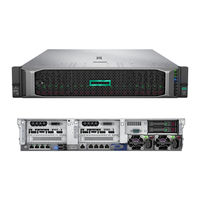
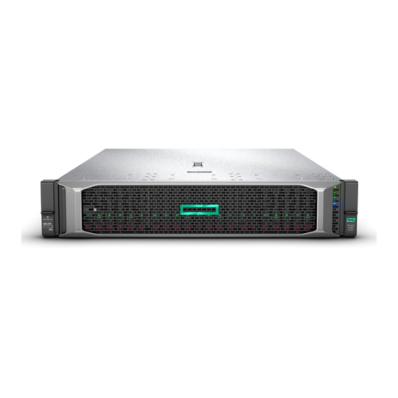
User Manuals: HPE ProLiant DL385 Gen10 Rack Server
Manuals and User Guides for HPE ProLiant DL385 Gen10 Rack Server. We have
4
HPE ProLiant DL385 Gen10 Rack Server manuals available for free PDF download: User Manual, Maintenance And Service Manual
HPE ProLiant DL385 Gen10 User Manual (177 pages)
Brand:
HPE
| Category:
Server
| Size: 9 MB
Table of Contents
Table of Contents
3
Component Identification
8
Front Panel Components
8
Front Panel Leds and Buttons
10
UID Button Functionality
14
Power Fault Leds
14
Systems Insight Display Leds
15
Systems Insight Display Combined LED Descriptions
16
Rear Panel Components
18
Rear Panel Leds
18
System Board Components
20
System Maintenance Switch Descriptions
21
DIMM Slot Locations
22
Processor and Socket Components
23
Drives
23
SAS/SATA Drive Components and Leds
23
Nvme Drive Components and Leds
24
Uff Drive Components and Leds
25
Fan Bay Numbering
26
Drive Box Identification
27
Drive Bay Numbering
28
Drive Bay Numbering: Smart Array Controller
29
Drive Bay Numbering: SAS Expander
30
Drive Bay Numbering: Nvme Drives
33
Uff Drive Bay Numbering
33
Operations
35
Power up the Server
35
Power down the Server
35
Extend the Server from the Rack
35
Extending the Server from the Rack
36
Removing the Server from the Rack
37
Installing the Server into the Rack
37
Remove the Access Panel
39
Installing the Access Panel
39
Removing the Fan Cage
40
Installing the Fan Cage
41
Removing the Air Baffle or Midplane Drive Cage
41
Installing the Air Baffle
43
Removing a Riser Cage
44
Removing a Riser Slot Blank
45
Removing the Hard Drive Blank
46
Releasing the Cable Management Arm
46
Accessing the Systems Insight Display
47
Setup
48
HPE Support Services
48
Setup Overview
48
Operational Requirements
49
Space and Airflow Requirements
49
Temperature Requirements
50
Power Requirements
50
Electrical Grounding Requirements
50
Server Warnings and Cautions
51
Rack Warnings
52
Electrostatic Discharge
52
Server Box Contents
53
Installing Hardware Options
53
Configuring the Server
53
Installing or Deploying an Operating System
53
Registering the Server
54
Hardware Options Installation
55
Product Quickspecs
55
Introduction
55
Installing the Bezel and Bezel Lock
55
Power Supply Options
56
Hot-Plug Power Supply Calculations
56
Installing a Redundant Hot-Plug Power Supply
56
Drive Options
57
Drive Guidelines
57
Supported Drive Carriers
58
Installing a Hot-Plug SAS or SATA Drive
58
Installing an Nvme Drive
59
Installing a Uff Drive and SCM Drive Carrier
60
Installing an M.2 Drive
61
Fan Options
62
Installing High-Performance Fans
63
Memory Options
65
Memory-Processor Compatibility Information
65
Smartmemory
66
Memory Subsystem Architecture
66
DIMM Ranks
66
DIMM Label Identification
67
Memory Configurations
68
Advanced ECC Memory Configuration
68
DIMM Population Information
68
Identifying the Processor Type
68
Installing a DIMM
69
Controller Options
70
Installing a Storage Controller
70
Installing a Universal Media Bay
72
Drive Cage Options
74
Installing a Front 8Nvme SSD Express Bay Drive Cage
74
Installing a Front 6SFF SAS/SATA + 2Nvme Premium Drive Cage
75
Installing Airflow Labels
77
Installing a Front 8SFF SAS/SATA Drive Cage in Box 1
79
Installing a Front 8SFF SAS/SATA Drive Cage in Box 2
81
Installing a Front 2SFF Nvme/Sas/Sata Premium Drive Cage
82
Installing a Midplane 4LFF SAS/SATA Drive Cage
85
Installing a Rear 2SFF SAS/SATA Drive Cage in the Primary or Secondary Riser
88
Installing a Rear 2SFF SAS/SATA Drive Cage over the Power Supplies
91
Installing a Rear 3LFF SAS/SATA Drive Cage
94
Riser and Riser Cage Options
95
Installing Primary and Secondary Risers
96
Installing Tertiary Risers
97
Installing a Secondary Riser Cage
98
Installing a Tertiary Riser Cage
99
Installing the 2Nvme Slimsas Riser Option
102
Installing the 8Nvme Slimsas Riser Option
103
Expansion Slots
104
Supported Pcie Form Factors
104
Installing Expansion Boards
105
Installing a 12G SAS Expander Card
107
Installing a GPU Card
110
Installing an Intrusion Detection Switch
114
Installing a Smart Storage Battery
115
Installing a Rear Serial Port Interface
116
Installing a Systems Insight Display
119
Installing a Flexiblelom Adapter
121
Installing a 1U or High-Performance Heatsink
123
Installing a Processor
125
HPE Trusted Platform Module 2.0 Gen10 Option
127
Overview
127
HPE Trusted Platform Module 2.0 Guidelines
128
Installing and Enabling the HPE TPM 2.0 Gen10 Kit
128
Installing the Trusted Platform Module Board
128
Enabling the Trusted Platform Module
131
Retaining the Recovery Key/Password
132
Cabling
134
HPE Proliant Gen10 DL Servers Storage Cabling Guidelines
134
Cabling Diagrams
134
Cable Routing: Front 2SFF SAS Side by Side for LFF
138
Cable Routing: Front 2SFF Drive Option for SFF
138
Cable Routing: Front 2SFF Drive Option for LFF
139
Cable Routing: Front/Rear 2Premium SAS (SFF + LFF)
139
Cable Routing: Front 8SFF SAS/SATA Drive Options
140
Cable Routing: Midplane 4LFF SAS/SATA Drive Option
142
Cable Routing: Rear 2SFF SAS/SATA Riser Drive Options
142
Cable Routing: Rear 3LFF SAS/SATA Drive Option for System Board
143
Cable Routing: Rear 3LFF SAS/SATA Drive Option for SAS Expander
144
Cable Routing: HPE 12G SAS Expander
144
Cable Routing: Front 2SFF Nvme Side-By-Side Drive Options
145
Cable Routing: Front/Rear 2SFF Premium
146
Cable Routing: Front 8SFF Nvme/Sas Premium Drive Option
146
Cable Routing: Front 8SFF Nvme Drive Options
147
Cable Routing: 8Nvme Bay 1 Drive Options
149
Cable Routing: Bays 1 and 2 8Premium
149
Cable Routing: External USB 2.0 Cable
150
Cable Routing: Systems Insight Display
150
Software and Configuration Utilities
152
Server Mode
152
Product Quickspecs
152
Active Health System Viewer
152
Active Health System
152
Active Health System Data Collection
153
Active Health System Log
153
HPE Ilo 5
153
Ilo Federation
154
Ilo Service Port
154
Ilo Restful API
155
Restful Interface Tool
155
Ilo Amplifier Pack
155
Intelligent Provisioning
155
Intelligent Provisioning Operation
156
Management Security
156
Scripting Toolkit for Windows and Linux
157
UEFI System Utilities
157
Selecting the Boot Mode
157
Secure Boot
158
Launching the Embedded UEFI Shell
159
HPE Smart Storage Administrator
159
USB Support
160
External USB Functionality
160
Redundant ROM Support
160
Safety and Security Benefits
160
Keeping the System Current
160
Updating Firmware or System ROM
160
Service Pack for Proliant
161
Updating Firmware from the System Utilities
162
Updating the Firmware from the UEFI Embedded Shell
163
Online Flash Components
163
Drivers
163
Software and Firmware
163
Operating System Version Support
164
HPE Pointnext Portfolio
164
Proactive Notifications
164
Troubleshooting
165
NMI Functionality
165
Troubleshooting Resources
165
Safety, Warranty, and Regulatory Information
166
Safety and Regulatory Compliance
166
Warranty Information
166
Regulatory Information
166
Belarus Kazakhstan Russia Marking
166
Turkey Rohs Material Content Declaration
167
Ukraine Rohs Material Content Declaration
167
Specifications
168
Environmental Specifications
168
Mechanical Specifications
168
Power Supply Specifications
169
HPE 500W Flex Slot Platinum Hot Plug Low Halogen Power Supply
170
HPE 800W Flex Slot Platinum Hot Plug Low Halogen Power Supply
171
HPE 800W Flex Slot Titanium Hot Plug Low Halogen Power Supply
171
HPE 800W Flex Slot Universal Hot Plug Low Halogen Power Supply
172
HPE 800W Flex Slot -48VDC Hot Plug Low Halogen Power Supply
173
HPE 1600W Flex Slot Platinum Hot Plug Low Halogen Power Supply
174
Support and Other Resources
175
Accessing Hewlett Packard Enterprise Support
175
Accessing Updates
175
Customer Self Repair
176
Remote Support
176
Warranty Information
176
Regulatory Information
177
Documentation Feedback
177
Advertisement
HPE ProLiant DL385 Gen10 User Manual (170 pages)
Brand:
HPE
| Category:
Server
| Size: 8 MB
Table of Contents
Table of Contents
3
Component Identification
8
Front Panel Components
8
Front Panel Leds and Buttons
10
UID Button Functionality
14
Power Fault Leds
14
Systems Insight Display Leds
14
Systems Insight Display Combined LED Descriptions
16
Rear Panel Components
18
Rear Panel Leds
18
System Board Components
19
System Maintenance Switch Descriptions
20
DIMM Label Identification
21
DIMM Slot Locations
22
Processor and Socket Components
23
Drive Box Identification
24
Drive Bay Numbering
26
Drive Bay Numbering: Smart Array Controller
26
Drive Bay Numbering: SAS Expander
28
Drive Bay Numbering: Nvme Drives
31
Drives
31
SAS/SATA Drive Components and Leds
31
Nvme Drive Components and Leds
32
Fan Bay Numbering
33
Operations
34
Power up the Server
34
Power down the Server
34
Extending the Server from the Rack
34
Secure Cables Using the Cable Management Arm
35
Removing the Server from the Rack
36
Remove the Access Panel
37
Install the Access Panel
37
Removing the Fan Cage
37
Installing the Fan Cage
38
Removing the Air Baffle or Midplane Drive Cage
39
Installing the Air Baffle
41
Removing a Riser Cage
41
Removing a Riser Slot Blank
42
Removing the Hard Drive Blank
43
Release the Cable Management Arm
43
Accessing the Systems Insight Display
44
Setup
45
Optional Service
45
Initial System Installation
45
HPE Installation Service
45
Setting up the Server
46
Operational Requirements
49
Space and Airflow Requirements
49
Temperature Requirements
50
Power Requirements
50
Electrical Grounding Requirements
50
Server Warnings and Cautions
51
Rack Warnings
52
Preventing Electrostatic Discharge
52
POST Screen Options
52
Installing or Deploying an Operating System
53
Hardware Options Installation
54
Introduction
54
Installing the Bezel and Bezel Lock
54
Drive Options
55
Drive Guidelines
55
Supported Drive Carriers
55
Installing a Hot-Plug SAS or SATA Drive or an Nvme Drive
55
Power Supply Options
57
Hot-Plug Power Supply Calculations
57
Installing a Redundant Hot-Plug Power Supply
57
Connecting a DC Power Cable to a DC Power Source
59
Installing a Universal Media Bay
60
Drive Cage Options
62
Installing a Front 8Nvme SSD Express Bay Drive Cage
62
Installing a Front 6 SFF SAS/SATA + 2 Nvme Premium Drive Cage
63
Installing a Front 8 SFF SAS/SATA Drive Cage in Box 1
65
Installing a Front 8 SFF SAS/SATA Drive Cage in Box 2
67
Installing a Front 2 SFF Nvme/Sas/Sata Premium Drive Cage
68
Installing a Midplane 4 LFF SAS/SATA Drive Cage
71
Installing a Midplane 8 SFF SAS/SATA Drive Cage
74
Installing a Rear 2 SFF SAS/SATA Drive Cage over the Power Supplies
77
Installing a Rear 2 SFF SAS/SATA Drive Cage in the Primary or Secondary Riser
81
Fan Options
83
Installing High-Performance Fans
84
Processor and Heatsink Options
86
Installing a Processor
86
Installing a 1U or High-Performance Heatsink
90
Memory Options
93
DIMM-Processor Compatibility
93
DIMM Population Information
93
Memory Speed Tables
94
Installing a DIMM
94
Controller Options
95
Installing a Storage Controller
96
Energy Pack Options
97
HPE Smart Storage Battery
97
HPE Smart Storage Hybrid Capacitor
97
Installing an Energy Pack
98
Riser and Riser Cage Options
100
Installing Primary and Secondary Risers
100
Installing Tertiary Risers
101
Installing a Secondary Riser Cage
102
Installing a Tertiary Riser Cage
103
Installing the 2 Nvme Slim SAS Riser Option
106
Installing the 8 Nvme Slim SAS Riser Option
107
Expansion Slots
108
Supported Pcie Form Factors
108
Installing Expansion Boards
109
Installing a 12G SAS Expander Card
111
Accelerator Options
113
Installing an OCP NIC 3.0 Adapter
117
Installing the Systems Insight Display
119
Installing the Chassis Intrusion Detection Switch
121
Installing a Rear Serial Port Interface
122
Cabling
124
HPE Proliant Gen10 Plus DL Servers Storage Cabling Guidelines
124
Cabling Diagrams
124
Cable Routing: 8 LFF Front I/O Module to SATA Port
128
Cable Routing: Universal Media Bay to SATA Port
129
Cable Routing: 2 SFF Slim SAS Universal Media Bay in Box 1 to System Board
129
Cable Routing: 2 SFF Side by Side SATA to System Board
130
Cable Routing: Front 8 SFF Drive Options (Box 3 to HPE Smart Array E208I-A SR Gen10 Controller, Ports 1-2)
130
Cable Routing: Front 8 SFF Drive Options (Box 1 to HPE Smart Array P816I-A SR Controller, Ports 3-4)
131
Cable Routing: 24 SFF SAS Drive Options (Box 1, Box 2, and Box 3 to SAS Expander)
131
Cable Routing: 24 SFF Drive Options (Box 1, Box 2, and Box 3 to SAS Expander Card and HPE Smart Array P816I-A SR Gen10 Controller, Ports 1-2)
132
Cable Routing: 8 Nvme Balanced Direct Solution
132
Cable Routing: 8 Nvme Direct Single Processor Solution
133
Cable Routing: 16 Nvme Balanced Direct Solution
133
Cable Routing: Front 8 LFF to System Board
134
Cable Routing: 12 LFF Drive Options (Midtray to System Board)
134
Cable Routing: Front 12 LFF Drive Options (Midtray to HPE Smart Array P816I-A SR Gen10 Controller, Ports 1-4)
135
Cable Routing: LFF Backplane to HPE Smart Array P816I-A SR Gen10 Controller
135
Cable Routing: System Board Processor 1 (Ports 1A and 2A) to Slotted Expansion Board Ports 1-2 in the Primary Riser
136
Cable Routing: SFF Front I/O Module to Front Power/Usb 3.1 Gen1 Connector
136
Cable Routing: Systems Insight Display to Front Power/Usb 3.1 Gen1 Connector
137
Cable Routing: 12 LFF Power Switch and Thermal Sensor to System Board
137
Cable Routing: 8 LFF Front I/O Module Display Port to System Board
138
Cable Routing: Display Port to System Board
138
Cable Routing: Universal Media Bay External USB to Dual USB Port on System Board
139
Cable Routing: Rear Serial Port Interface
139
Cable Routing: Rear Serial Port Interface (Tertiary Riser)
140
Cable Routing: SFF Backplane Power Cabling to the System Board
140
Cable Routing: LFF Backplane Power Cabling to the System Board
141
Cable Routing: 4 LFF Backplane and 2 SFF Side by Side LFF Power Cable Connections to the System Board
141
Cable Routing: Rear 2 SFF Riser Power Cable
142
Software and Configuration Utilities
143
Server Mode
143
Product Quickspecs
143
Active Health System Viewer
143
Active Health System
143
HPE Ilo 5
144
Ilo Federation
145
Ilo Service Port
145
Ilo Restful API
146
Restful Interface Tool
146
Ilo Amplifier Pack
146
Integrated Management Log
146
Intelligent Provisioning
147
Intelligent Provisioning Operation
147
Management Security
148
Scripting Toolkit for Windows and Linux
148
UEFI System Utilities
148
Selecting the Boot Mode
149
Secure Boot
149
Launching the Embedded UEFI Shell
150
HPE Smart Storage Administrator
151
HPE Infosight for Servers
151
USB Support
151
External USB Functionality
151
Redundant ROM Support
152
Safety and Security Benefits
152
Keeping the System Current
152
Updating Firmware or System ROM
152
Drivers
154
Software and Firmware
155
Operating System Version Support
155
HPE Pointnext Portfolio
155
Proactive Notifications
155
Troubleshooting
157
NMI Functionality
157
Troubleshooting Resources
157
System Battery Replacement
158
System Battery Information
158
Replace the System Battery
158
Specifications
160
Environmental Specifications
160
Mechanical Specifications
160
Power Supply Specifications
161
HPE 500W Flex Slot Platinum Hot-Plug Low Halogen Power Supply
161
HPE 800W Flex Slot Platinum Hot-Plug Low Halogen Power Supply
162
HPE 800W Flex Slot Titanium Hot-Plug Low Halogen Power Supply
163
HPE 800W Flex Slot Universal Hot-Plug Low Halogen Power Supply
164
HPE 800W Flex Slot -48VDC Hot-Plug Low Halogen Power Supply
164
HPE 1600W Flex Slot Platinum Hot-Plug Low Halogen Power Supply
166
Websites
167
Support and Other Resources
168
Accessing Hewlett Packard Enterprise Support
168
Accessing Updates
168
Customer Self Repair
169
Remote Support
169
Warranty Information
169
Regulatory Information
170
Documentation Feedback
170
HPE ProLiant DL385 Gen10 Maintenance And Service Manual (166 pages)
Brand:
HPE
| Category:
Server
| Size: 9 MB
Table of Contents
Table of Contents
3
Illustrated Parts Catalog
7
Mechanical Components
7
Air Baffle Spare Part
7
Access Panel Spare Parts
8
Tertiary PCI Riser Cage Spare Part
8
Primary and Secondary PCI Riser Cage Spare Part
8
Chassis Ear Spare Parts
8
Fan Cage Spare Part
8
2U Bezel Spare Part
8
Rail Kit Spare Parts
9
Miscellaneous Mechanical Spare Parts
9
System Components
10
DIMM Spare Parts
11
Processor Spare Parts
11
Heatsink Spare Parts
12
Power Supply Spare Parts
12
Smart Array Controller Spare Parts
13
Network Adapter Spare Parts
13
PCI Riser Board Spare Parts
15
System Board Spare Parts
15
LFF Front I/O Board Spare Part
15
System Battery Spare Part
15
Server Options
16
Drive Spare Parts
16
Fan Spare Parts
20
Drive Backplane Board Spare Parts
21
Chassis Intrusion Detection Switch Spare Part
21
Rear Serial Port Interface Spare Part
21
Accelerator Spare Parts
21
HPE Dl38X Gen10 12Gb SAS Expander Card Spare Part
22
Energy Pack Spare Parts
22
Power Module Spare Parts
22
HPE Trusted Platform Module 2.0 Spare Part
22
Cable Spare Parts
23
Thermal Grease Spare Part
23
Customer Self Repair
24
Removal and Replacement Procedures
33
Required Tools
33
Safety Considerations
33
Preventing Electrostatic Discharge
33
Symbols on Equipment
33
Server Warnings and Cautions
34
Preparation Procedures
35
Access the Systems Insight Display
35
Power down the Server
36
Extend the Server from the Rack
36
Remove the Server from the Rack
37
Access the Product Rear Panel
37
Remove the Access Panel
38
Removing the Air Baffle
38
Release the Full-Length Expansion Board Retainer
39
Removing and Replacing a Drive Blank
40
Removing and Replacing Drives
41
Removing and Replacing a Hot-Plug Drive
41
Removing and Replacing an Nvme Drive
41
Removing and Replacing an M.2 SSD
42
Removing and Replacing the Hot-Plug Fan
43
Removing and Replacing a Power Supply Blank
44
Removing and Replacing the AC Power Supply
44
Removing and Replacing the Primary or Secondary Pcie Riser Cages
45
Removing and Replacing the Tertiary Pcie Riser Cage
46
Removing and Replacing the Pcie Riser Blank
47
Removing and Replacing the Pcie Riser Board
48
Removing and Replacing an Expansion Slot Blank
50
Removing and Replacing an Expansion Board
51
Removing and Replacing the Fan Cage
52
Removing and Replacing the Flexiblelom
53
Removing and Replacing the Small Form Factor Universal Media Bay
54
Removing and Replacing the LFF Power Switch Module
55
Removing and Replacing the SFF Optical Drive
56
Removing and Replacing the LFF Optical Drive
58
Removing and Replacing the 8SFF Drive Cage
59
Removing and Replacing the 8SFF Drive Backplane
60
Removing and Replacing the 2SFF Front Drive Cage
61
Removing and Replacing the 2SFF Rear Drive Bay and Riser Cage
62
Removing and Replacing the 2SFF Drive Cage
63
Removing and Replacing the 2SFF Rear Drive Backplane
64
Removing and Replacing a 4LFF Midplane Cage
65
Removing and Replacing a 3LFF Rear Drive Cage
66
Removing and Replacing the 3LFF Rear Drive Backplane
67
Removing and Replacing the LFF Backplane Assembly
68
Removing and Replacing a Front LFF Drive Backplane
69
Removing and Replacing a Rear Serial Port Interface (Primary/Secondary)
70
Removing and Replacing a Rear Serial Port Interface (Tertiary Riser)
71
Removing a Rear Serial Port Interface (Tertiary)
71
Replacing a Rear Serial Port Interface (Tertiary)
72
Removing and Replacing an SFF Power Switch Module
72
Removing and Replacing an SFF Chassis Ear
73
Removing and Replacing the Front I/O Board in the LFF Right Chassis Ear
74
Removing and Replacing the LFF Chassis Ear Assembly
76
Removing and Replacing an Accelerator or GPU
78
DIMM-Processor Compatibility
79
Removing and Replacing a DIMM
80
Removing and Replacing a Heatsink
81
Removing and Replacing a Processor
83
Removing and Replacing an Energy Pack
88
Removing and Replacing a Smart Array Type-A Modular Controller
89
System Battery Replacement
90
System Battery Information
90
Replace the System Battery
90
Removing and Replacing the System Board
91
Removing the System Board
91
Replacing the System Board
94
Re-Entering the Server Serial Number and Product ID
98
HPE Trusted Platform Module 2.0 Gen10 Option
99
Troubleshooting
100
NMI Functionality
100
Troubleshooting Resources
100
Diagnostic Tools
101
Product Quickspecs
101
UEFI System Utilities
101
Selecting the Boot Mode
101
Secure Boot
102
Launching the Embedded UEFI Shell
102
Intelligent Provisioning
103
Intelligent Provisioning Operation
103
HPE Insight Remote Support
104
USB Support
105
External USB Functionality
105
HPE Smart Storage Administrator
105
HPE MR Storage Administrator
105
HPE Infosight for Servers
106
Storcli
106
Component Identification
107
Front Panel Components
107
Front Panel Leds and Buttons
109
UID Button Functionality
113
Power Fault Leds
113
Systems Insight Display Leds
113
Systems Insight Display Combined LED Descriptions
115
Rear Panel Components
117
Rear Panel Leds
117
System Board Components
119
System Maintenance Switch Descriptions
120
DIMM Label Identification
121
DIMM Slot Locations
122
Processor and Socket Components
123
Drive Box Identification
124
Drive Bay Numbering
125
Drive Bay Numbering: Smart Array Controller
126
Drive Bay Numbering: SAS Expander
127
Drive Bay Numbering: Nvme Drives
130
Uff Drive Bay Numbering
130
Drives
131
SAS/SATA Drive Components and Leds
131
Nvme SSD LED Definitions
132
Nvme SSD Button Actions
133
Uff Drive Components and Leds
134
Fan Bay Numbering
135
Cabling
136
HPE Proliant Gen10 DL Servers Storage Cabling Guidelines
136
Cabling Diagrams
136
Cable Routing: Front 2SFF SAS Side by Side for LFF
139
Cable Routing: Front 2SFF Drive Option for SFF
140
Cable Routing: Front 2SFF Drive Option for LFF
140
Cable Routing: Front/Rear 2Premium SAS (SFF + LFF)
140
Cable Routing: Front 8SFF SAS/SATA Drive Options
141
Cable Routing: Midplane 4LFF SAS/SATA Drive Option
143
Cabling Diagram: MID 4LFF SAS/SATA Drive Cage for System Board
144
Cable Routing: Rear 2SFF SAS/SATA Riser Drive Options
144
Cable Routing: Rear 3LFF SAS/SATA Drive Option for System Board
145
Cable Routing: Rear 3LFF SAS/SATA Drive Option for SAS Expander
146
Cable Routing: HPE 12G SAS Expander
146
Cable Routing: Front 2SFF Nvme Side-By-Side Drive Options
147
Cable Routing: Front/Rear 2SFF Premium
148
Cable Routing: Front 8SFF Nvme/Sas Premium Drive Option
148
Cable Routing: Front 8SFF Nvme Drive Options
149
Cable Routing: 8Nvme Bay 1 Drive Options
151
Cable Routing: Bays 1 and 2 8Premium
151
Cable Routing: Storage Controller Backup Power Cable
152
Cable Routing: External USB 2.0 Cable
152
Cable Routing: Power Switch Module/Sid Module
153
Specifications
154
Environmental Specifications
154
Mechanical Specifications
154
Power Supply Specifications
155
HPE 500W Flex Slot Platinum Hot-Plug Low Halogen Power Supply
155
HPE 800W Flex Slot Platinum Hot-Plug Low Halogen Power Supply
156
HPE 800W Flex Slot Titanium Hot-Plug Low Halogen Power Supply
157
HPE 800W Flex Slot Universal Hot-Plug Low Halogen Power Supply
158
HPE 800W Flex Slot -48VDC Hot-Plug Low Halogen Power Supply
158
HPE 1600W Flex Slot Platinum Hot-Plug Low Halogen Power Supply
160
Websites
161
Support and Other Resources
162
Accessing Hewlett Packard Enterprise Support
162
Accessing Updates
162
Remote Support
163
Warranty Information
163
Regulatory Information
163
Documentation Feedback
164
Acronyms and Abbreviations
165
Advertisement
HPE ProLiant DL385 Gen10 Maintenance And Service Manual (149 pages)
Brand:
HPE
| Category:
Server
| Size: 8 MB
Table of Contents
Table of Contents
3
Illustrated Parts Catalog
7
Mechanical Components
7
Air Baffle Spare Part
7
Access Panel Spare Parts
8
Tertiary PCI Riser Cage Spare Part
8
Primary and Secondary PCI Riser Cage Spare Part
8
Chassis Ear Spare Parts
8
Fan Cage Spare Part
8
Bezel Spare Part
8
Rail Kit Spare Parts
9
Miscellaneous Blank Kits Spare Parts
9
System Components
10
DIMM Spare Parts
11
Processor Spare Parts
12
Heatsink Spare Parts
12
Power Supply Spare Parts
12
Controller Spare Parts
13
PCI Riser Board Spare Parts
14
Ethernet Adapter Spare Parts
14
Flexiblelom Adapter Spare Parts
14
System Board Spare Part
15
System Battery Spare Part
15
Server Options
15
Drive Spare Parts
16
Fan Spare Part
20
Backplane Board Spare Parts
20
Chassis Intrusion Detection Switch Spare Part
21
Rear Serial Port Interface Spare Part
21
GPU Option Spare Part
21
HPE 12Gb Dl38X Gen10 SAS Expander Card Spare Part
21
HPE Smart Storage Battery Spare Parts
21
Power Module Spare Part
22
LFF I/O UID Spare Parts
22
HPE Trusted Platform Module 2.0 Spare Part
22
Cable Spare Parts
22
Thermal Grease Spare Parts
23
Customer Self Repair
24
Removal and Replacement Procedures
34
Required Tools
34
Safety Considerations
34
Preventing Electrostatic Discharge
34
Symbols on Equipment
34
Server Warnings and Cautions
35
Preparation Procedures
35
Power down the Server
35
Extend the Server from the Rack
36
Remove the Server from the Rack
37
Access the Product Rear Panel
37
Access the Systems Insight Display
37
Remove the Access Panel
38
Remove the Air Baffle
38
Release the Full-Length Expansion Board Retainer
39
Removing and Replacing a Drive Blank
41
Removing and Replacing Drives
41
Removing and Replacing a Hot-Plug Drive
41
Removing and Replacing an Nvme Drive
42
Removing and Replacing an M.2 SSD
42
Removing and Replacing the Hot-Plug Fan
43
Removing and Replacing a Power Supply Blank
44
Removing and Replacing the AC Power Supply
44
Removing and Replacing the Primary or Secondary Pcie Riser Cages
45
Removing and Replacing the Tertiary Pcie Riser Cage
46
Removing and Replacing the Pcie Riser Blank
47
Removing and Replacing the Pcie Riser Board
48
Removing and Replacing an Expansion Slot Blank
50
Removing and Replacing an Expansion Board
51
Removing and Replacing the Fan Cage
52
Removing and Replacing the Flexiblelom
53
Removing and Replacing the Small Form Factor Universal Media Bay
54
Removing and Replacing the LFF Power Switch Module
55
Removing and Replacing the SFF Optical Drive
56
Removing and Replacing the LFF Optical Drive
58
Removing and Replacing the 8SFF Drive Cage
59
Removing and Replacing the 8SFF Drive Backplane
60
Removing and Replacing the 2SFF Front Drive Cage
61
Removing and Replacing the 2SFF Rear Drive Bay and Riser Cage
62
Removing and Replacing the 2SFF Drive Cage
63
Removing and Replacing the 2SFF Rear Drive Backplane
64
Removing and Replacing a 4LFF Midplane Cage
65
Removing and Replacing a 3LFF Rear Drive Cage
66
Removing and Replacing the LFF Backplane Assembly
67
Removing and Replacing a Front LFF Drive Backplane
68
Removing and Replacing the 3LFF Rear Drive Backplane
69
Removing and Replacing a Rear Serial Port Interface (Primary/Secondary)
70
Removing and Replacing a Rear Serial Port Interface (Tertiary Riser)
71
Removing a Rear Serial Port Interface (Tertiary)
71
Replacing a Rear Serial Port Interface (Tertiary)
72
Removing and Replacing an SFF Power Switch Module
72
Removing and Replacing an LFF Chassis Ear with Power/Uid
73
Removing and Replacing an SFF Standard Chassis Ear
75
Removing and Replacing a GPU Enablement Board
76
Removing and Replacing a DIMM
77
Removing and Replacing a Processor
78
Removing and Replacing the HPE Smart Storage Battery
81
Removing and Replacing a Type -A Smart Array Controller
82
Removing and Replacing the System Battery
83
Removing and Replacing the System Board
84
Re-Entering the Server Serial Number and Product ID
87
HPE Trusted Platform Module 2.0 Gen10 Option
88
Cabling
89
HPE Proliant Gen10 DL Servers Storage Cabling Guidelines
89
Cabling Diagrams
89
Cable Routing: Front 2SFF SAS Side by Side for LFF
92
Cable Routing: Front 2SFF Drive Option for SFF
93
Cable Routing: Front 2SFF Drive Option for LFF
93
Cable Routing: Front/Rear 2Premium SAS (SFF + LFF)
94
Cable Routing: Front 8SFF SAS/SATA Drive Options
95
Cable Routing: Midplane 4LFF SAS/SATA Drive Option
97
Cable Routing: Rear 2SFF SAS/SATA Riser Drive Options
97
Cable Routing: Rear 3LFF SAS/SATA Drive Option for System Board
98
Cable Routing: Rear 3LFF SAS/SATA Drive Option for SAS Expander
99
Cable Routing: HPE 12G SAS Expander
99
Cable Routing: Front 2SFF Nvme Side-By-Side Drive Options
100
Cable Routing: Front/Rear 2SFF Premium
101
Cable Routing: Front 8SFF Nvme/Sas Premium Drive Option
101
Cable Routing: Front 8SFF Nvme Drive Options
102
Cable Routing: 8Nvme Bay 1 Drive Options
104
Cable Routing: Bays 1 and 2 8Premium
104
Cable Routing: External USB 2.0 Cable
105
Cable Routing: Systems Insight Display
105
Diagnostic Tools
107
Product Quickspecs
107
UEFI System Utilities
107
Selecting the Boot Mode
107
Secure Boot
108
Launching the Embedded UEFI Shell
109
Intelligent Provisioning
109
Intelligent Provisioning Operation
110
HPE Insight Remote Support
110
USB Support
111
External USB Functionality
111
HPE Smart Storage Administrator
111
Troubleshooting
112
Troubleshooting Resources
112
Component Identification
113
Front Panel Components
113
Front Panel Leds and Buttons
115
UID Button Functionality
119
Power Fault Leds
119
Systems Insight Display Leds
120
Systems Insight Display Combined LED Descriptions
121
Rear Panel Components
123
Rear Panel Leds
123
System Board Components
125
System Maintenance Switch Descriptions
126
DIMM Slot Locations
127
Processor and Socket Components
128
Drives
128
SAS/SATA Drive Components and Leds
128
Nvme Drive Components and Leds
129
Uff Drive Components and Leds
130
Fan Bay Numbering
131
Drive Box Identification
132
Drive Bay Numbering
133
Drive Bay Numbering: Smart Array Controller
134
Drive Bay Numbering: SAS Expander
135
Drive Bay Numbering: Nvme Drives
138
Uff Drive Bay Numbering
138
Specifications
140
Environmental Specifications
140
Mechanical Specifications
140
Power Supply Specifications
141
HPE 500W Flex Slot Platinum Hot Plug Low Halogen Power Supply
142
HPE 800W Flex Slot Platinum Hot Plug Low Halogen Power Supply
143
HPE 800W Flex Slot Titanium Hot Plug Low Halogen Power Supply
143
HPE 800W Flex Slot Universal Hot Plug Low Halogen Power Supply
144
HPE 800W Flex Slot -48VDC Hot Plug Low Halogen Power Supply
145
HPE 1600W Flex Slot Platinum Hot Plug Low Halogen Power Supply
146
Acronyms and Abbreviations
147
Documentation Feedback
149
Advertisement
Related Products
HPE ProLiant DL385 Gen10 Plus
HPE ProLiant DL385
HPE ProLiant DL385 Gen11
HPE DL380 G9
HPE ProLiant DL380 Gen10
HPE ProLiant DL388 Gen10
HPE ProLiant DL380 Gen11
HPE ProLiant DL380 Gen10 Plus
HPE ProLiant DL360 Gen10 Plus
HPE ProLiant DL365 Gen11
HPE Categories
Server
Switch
Network Router
Storage
Wireless Access Point
More HPE Manuals
Login
Sign In
OR
Sign in with Facebook
Sign in with Google
Upload manual
Upload from disk
Upload from URL