Table of Contents
Advertisement
Quick Links
HPE ProLiant DL385 Gen10 Plus Server User
Guide
Abstract
This document is for the person who installs, administers, and troubleshoots servers and storage systems.
Hewlett Packard Enterprise assumes you are qualified in the servicing of computer equipment and trained in
recognizing hazards in products with hazardous energy levels.
Part Number: P16394-001
Published: December 2019
Edition: 1
Advertisement
Table of Contents

Related Manuals for HPE ProLiant DL385 Gen10 Plus


Summary of Contents for HPE ProLiant DL385 Gen10 Plus
- Page 1 HPE ProLiant DL385 Gen10 Plus Server User Guide Abstract This document is for the person who installs, administers, and troubleshoots servers and storage systems. Hewlett Packard Enterprise assumes you are qualified in the servicing of computer equipment and trained in recognizing hazards in products with hazardous energy levels.
- Page 2 © Copyright 2019 Hewlett Packard Enterprise Development LP Notices The information contained herein is subject to change without notice. The only warranties for Hewlett Packard Enterprise products and services are set forth in the express warranty statements accompanying such products and services. Nothing herein should be construed as constituting an additional warranty.
-
Page 3: Table Of Contents
Installing the air baffle....................................... 41 Removing a riser cage........................................41 Removing a riser slot blank.....................................42 Removing the hard drive blank.................................... 43 Release the cable management arm ................................43 Accessing the Systems Insight Display................................44 Setup..........................45 Optional service..........................................45 Initial system installation......................................45 HPE Installation Service..................................45... - Page 4 Memory speed tables....................................94 Installing a DIMM......................................94 Controller options.........................................95 Installing a storage controller................................96 Energy pack options........................................97 HPE Smart Storage Battery.................................. 97 HPE Smart Storage Hybrid Capacitor.............................97 Installing an energy pack..................................98 Riser and riser cage options....................................100 Installing primary and secondary risers............................100 Installing tertiary risers..................................101...
- Page 5 Cable routing: 24 SFF SAS drive options (box 1, box 2, and box 3 to SAS expander)........131 Cable routing: 24 SFF drive options (box 1, box 2, and box 3 to SAS expander card and HPE Smart Array P816i-a SR Gen10 Controller, ports 1-2)......................132 Cable routing: 8 NVMe Balanced Direct Solution........................132...
- Page 6 Environmental specifications....................................160 Mechanical specifications......................................160 Power supply specifications....................................161 HPE 500W Flex Slot Platinum Hot-plug Low Halogen Power Supply..............161 HPE 800W Flex Slot Platinum Hot-plug Low Halogen Power Supply..............162 HPE 800W Flex Slot Titanium Hot-plug Low Halogen Power Supply..............163 HPE 800W Flex Slot Universal Hot-plug Low Halogen Power Supply..............
- Page 7 Websites......................... 167 Support and other resources..................168 Accessing Hewlett Packard Enterprise Support............................. 168 Accessing updates........................................168 Customer self repair.........................................169 Remote support..........................................169 Warranty information......................................169 Regulatory information......................................170 Documentation feedback......................................170...
-
Page 8: Component Identification
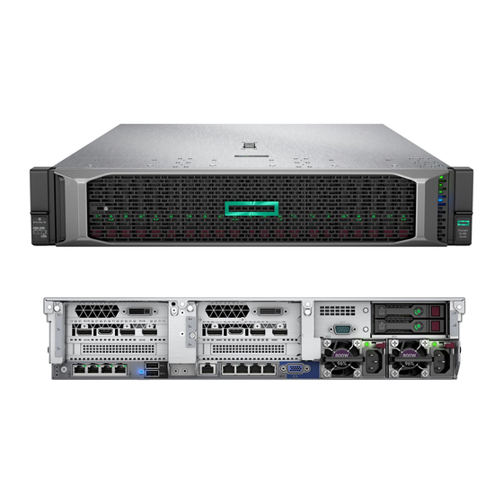
Component identification Front panel components SFF front panel components Item Description Box 1 (optional drives or universal media bay) Box 2 (optional drives) Box 3 drives 1 through 8 Serial label pull tab or optional Systems Insight Display iLO service port USB 3.1 Gen1 port Universal media bay components Item... - Page 9 12 LFF front panel components Item Description Drive bays 8 LFF front panel components Item Description Drives (optional) LFF power switch module Drive bays LFF power switch module components Component identification...
-
Page 10: Front Panel Leds And Buttons
Item Description Optical disc drive Serial label pull tab USB 3.1 Gen1 port iLO service port Video display port Front panel LEDs and buttons SFF front panel LEDs and button Item Description Status Power On/Standby button and • Solid green = System on system power LED •... - Page 11 Item Description Status NIC status LED • Solid green = Link to network • Flashing green (1 Hz/cycle per sec) = Network active • Off = No network activity UID button/LED • Solid blue = Activated • Flashing blue: ◦ 1 Hz/cycle per sec = Remote management or firmware upgrade in progress ◦...
- Page 12 Item Description Status Health LED • Solid green = Normal • Flashing green (1 Hz/cycle per sec) = iLO is rebooting • Flashing amber = System degraded • Flashing red (1 Hz/cycle per sec) = System critical Power On/Standby button and •...
- Page 13 LFF power switch module LEDs and button Item Description Status UID button/LED • Solid blue = Activated • Flashing blue: ◦ 1 Hz/cycle per sec = Remote management or firmware upgrade in progress ◦ 4 Hz/cycle per sec = iLO manual reboot sequence initiated ◦...
-
Page 14: Uid Button Functionality
UID button functionality The UID button can be used to display the Server Health Summary when the server will not power on. For more information, see the latest HPE iLO 5 User Guide on the Hewlett Packard Enterprise website. Power fault LEDs The following table provides a list of power fault LEDs, and the subsystems that are affected. - Page 15 Description Status Processor LEDs • Off = Normal • Amber = Failed processor DIMM LEDs • Off = Normal • Amber = Failed DIMM or configuration issue Fan LEDs • Off = Normal • Amber = Failed fan or missing fan NIC LEDs •...
-
Page 16: Systems Insight Display Combined Led Descriptions
Description Status AMP status LED • Off = AMP modes disabled • Solid green = AMP mode enabled • Solid amber = Failover • Flashing amber = Invalid configuration Power cap LED • Off = System is in standby, or no cap is set •... - Page 17 Systems Insight Display LED Health LED System power Status and color Over temp (amber) Amber The server has detected a hardware critical temperature level. PCI riser (amber) Green The PCI riser cage is not seated properly. Fan (amber) Amber Green One fan has failed or has been removed.
-
Page 18: Rear Panel Components
Rear panel components Item Description Primary riser slots 1–3 (optional drive cage) Optional secondary riser slots 4–6 (optional drive cage) Serial port (optional) Optional tertiary riser slots 7–8 (optional drive cage) Power supply 1 Power supply 2 Video port OCP NIC 3.0 slot USB 3.1 Gen1 connectors (2) Dedicated iLO management port When a secondary or tertiary riser cage is installed as shown, the serial port can be installed in the riser slot 8. -
Page 19: System Board Components
Item Description Status UID LED • Off = Deactivated • Solid blue = Activated • Flashing blue = System is being managed remotely Status LED • Off = No network activity • Solid green = Link to network • Flashing green = Network activity Link LED •... -
Page 20: System Maintenance Switch Descriptions
Item Description Display port/USB connector Primary (processor 1) PCIe riser connector x2 SATA port 1 NVMe port 8A x1 SATA port 2 Front power/USB 3.1 Gen1 connector Optical/SATA port 3 DIMMs Processor 1 Drive backplane power connectors NVMe port 2A NVMe port 1A Energy Pack connector NVMe port 2B... -
Page 21: Dimm Label Identification
Position Default Function Reserved Reserved • Off = Power-on password is enabled. • On = Power-on password is disabled. • Off = No function • On = Restore default manufacturing settings Reserved — Reserved — Reserved — Reserved — Reserved —... -
Page 22: Dimm Slot Locations
AA = CAS 26-22-22 (for 3DS LRDIMM) DIMM type R = RDIMM (registered) L = LRDIMM (load reduced) For more information about product features, specifications, options, configurations, and compatibility, see the HPE DDR4 SmartMemory QuickSpecs on the Hewlett Packard Enterprise website (https://www.hpe.com/support/ DDR4SmartMemoryQS). DIMM slot locations DIMM slots are numbered sequentially (1 through 16) for each processor. -
Page 23: Processor And Socket Components
Processor and socket components Item Description Pin field Rail frame Carrier frame Processor Force frame Captive screws (Torx T-20) Component identification... -
Page 24: Drive Box Identification
Drive box identification Front boxes Item Description Box 1 Box 2 Box 3 Item Description Box 1 Box 2 Box 3 Rear boxes Item Description Box 4 Box 5 Box 6 Component identification... - Page 25 Item Description Box 4 Box 5 Midplane box (LFF) Item Description Box 7 Component identification...
-
Page 26: Drive Bay Numbering
Midplane box (SFF) Item Description Box 7 Drive bay numbering Drive bay numbering depends on how the drive backplanes are connected: • To a controller: ◦ Embedded controllers use the onboard SATA ports. ◦ Type-a controllers install to the type-a smart array connector. ◦... - Page 27 12 LFF 6 SFF rear panel 2x 2 LFF rear panel Universal media bay 8 LFF + Universal media bay, optional 2 SFF, and optical drive Component identification...
-
Page 28: Drive Bay Numbering: Sas Expander
Midplane box LFF Midplane box SFF Drive bay numbering: SAS expander Drive numbering through a SAS Expander is continuous: • SAS expander port 1 always connects to port 1 of the controller. • SAS expander port 2 always connects to port 2 of the controller. •... - Page 29 • SAS expander port 8 = drive numbers 21 to 24. • SAS expander port 9 = drive numbers 25 to 28. Common configuration examples: NVMe drives When any stacked 2 SFF drive cage is connected to the SAS expander, the drive numbering skips the second number. For example, when a rear 2 SFF drive cage is connected to SAS expander port 9, then the drive numbers are 25 and 27.
- Page 30 12 LFF front panel Midplane box (LFF) Midplane box (SFF) Component identification...
-
Page 31: Drive Bay Numbering: Nvme Drives
Front 12 LFF + Midplane 4 LFF + All rear 2 SFF Drive bay numbering: NVMe drives Server populated with NVMe drives and NVMe risers Drives SAS/SATA drive components and LEDs Item Description Status Locate • Solid blue = The drive is being identified by a host application. -
Page 32: Nvme Drive Components And Leds
Item Description Status Do not remove LED • Solid white = Do not remove the drive. Removing the drive causes one or more of the logical drives to fail. • Off = Removing the drive does not cause a logical drive to fail. -
Page 33: Fan Bay Numbering
Fan bay numbering Component identification... -
Page 34: Operations
Operations Power up the server To power up the server, use one of the following methods: • Press the Power On/Standby button. • Use the virtual power button through iLO. Power down the server Before powering down the server for any upgrade or maintenance procedures, perform a backup of critical server data and programs. -
Page 35: Secure Cables Using The Cable Management Arm
Secure cables using the cable management arm For rack rail installation instructions, see the documentation that ships with the rack rails. WARNING: To reduce the risk of electric shock, fire, or damage to the equipment: • Do not insert wrong connectors into ports. •... -
Page 36: Removing The Server From The Rack
4. Secure the cables to the cable management arm. IMPORTANT: Leave enough slack in each of the cables to prevent damage to the cables when the server is extended from the rack. 5. Connect the power cord to the AC power source. Removing the server from the rack To remove the server from a Hewlett Packard Enterprise, Compaq-branded, Telco, or third-party rack: Procedure... -
Page 37: Remove The Access Panel
For more information, see the documentation that ships with the rack mounting option. 4. Place the server on a sturdy, level surface. Remove the access panel WARNING: To reduce the risk of personal injury from hot surfaces, allow the drives, power supplies, and internal system components to cool before touching them. -
Page 38: Installing The Fan Cage
Extend the server from the rack. • Remove the server from the rack. • 4. Remove the access panel. 5. Remove the air baffle. 6. Remove the fan cage. Installing the fan cage CAUTION: Do not operate the server for long periods with the access panel open or removed. Operating the server in this manner results in improper airflow and improper cooling that can lead to thermal damage. -
Page 39: Removing The Air Baffle Or Midplane Drive Cage
Removing the air baffle or midplane drive cage CAUTION: Do not detach the cable that connects the battery pack to the cache module. Detaching the cable causes any unsaved data in the cache module to be lost. CAUTION: For proper cooling, do not operate the server without the access panel, baffles, expansion slot covers, or blanks installed. - Page 40 • Remove the 4LFF midplane drive cage: a. Disconnect all cables. b. Remove all drives. Be sure to note the location of each drive. c. Remove the drive cage. CAUTION: Do not drop the drive cage on the system board. Dropping the drive cage on the system board might damage the system or components.
-
Page 41: Installing The Air Baffle
Installing the air baffle Procedure 1. Observe the following alerts. CAUTION: For proper cooling, do not operate the server without the access panel, baffles, expansion slot covers, or blanks installed. If the server supports hot-plug components, minimize the amount of time the access panel is open. -
Page 42: Removing A Riser Slot Blank
Extend the server from the rack. • Remove the server from the rack. • 4. Remove the access panel. 5. Remove the riser cage: • Primary riser cage • Secondary and tertiary riser cages Removing a riser slot blank CAUTION: To prevent improper cooling and thermal damage, do not operate the server unless all PCI slots have either an expansion slot cover or an expansion board installed. -
Page 43: Removing The Hard Drive Blank
Procedure 1. Power down the server. 2. Remove all power: a. Disconnect each power cord from the power source. b. Disconnect each power cord from the server. 3. Do one of the following: Extend the server from the rack. • Remove the server from the rack. -
Page 44: Accessing The Systems Insight Display
Accessing the Systems Insight Display The Systems Insight Display is supported only on SFF models. Procedure 1. Press and release the panel. 2. After the display fully ejects, rotate the display to view the LEDs. Operations... -
Page 45: Setup
HPE-supported products from other vendors that are sold by HPE or by HPE authorized resellers. The Installation Service is part of a suite of HPE deployment services that are designed to give users the peace of mind that comes from knowing that their HPE and HPE-supported products have been installed by an HPE specialist. -
Page 46: Setting Up The Server
Full coverage during the warranty period for products that require installation by an HPE authorized technical specialist. For more information on the features, limitations, provisions, and ordering information of the HPE Installation Service, see this Hewlett Packard Enterprise website: http://www.hpe.com/support/installation-service... - Page 47 Remotely: Connect to the iLO web interface and run a remote console: a. Verify the following: ◦ iLO is licensed to use the remote console feature. If iLO is not licensed, visit the HPE website: http://www.hpe.com/info/ilo ◦ The iLO management port is connected to a secure network.
- Page 48 Intelligent Provisioning and Smart Storage Administrator does not support Smart Array MR controller configuration. IMPORTANT: Before you install an OS on drives connected to the HPE Smart Array P824i-p MR Gen10 Controller, configure the drives using UEFI System Utilities (F9). If the drives are not configured, the OS will not detect the drives during installation.
-
Page 49: Operational Requirements
For Intelligent Provisioning 3.30 and later, you are prompted to select whether you want to enter the Intelligent Provisioning or HPE Rapid Setup Software mode. After you have selected a mode, you must reprovision the server to change the mode that launches when you boot to F10. -
Page 50: Temperature Requirements
CAUTION: If a third-party rack is used, observe the following additional requirements to ensure adequate airflow and to prevent damage to the equipment: • Front and rear doors—If the 42U rack includes closing front and rear doors, you must allow 5,350 sq cm (830 sq in) of holes evenly distributed from top to bottom to permit adequate airflow (equivalent to the required 64 percent open area for ventilation). -
Page 51: Server Warnings And Cautions
with IEC 60309 are considered suitable for this purpose. Using common power outlet strips for the server is not recommended. Server warnings and cautions WARNING: This server is heavy. To reduce the risk of personal injury or damage to the equipment: •... -
Page 52: Rack Warnings
Rack warnings WARNING: To reduce the risk of personal injury or damage to the equipment, be sure that: • The leveling jacks are extended to the floor. • The full weight of the rack rests on the leveling jacks. • The stabilizing feet are attached to the rack if it is a single-rack installation. -
Page 53: Installing Or Deploying An Operating System
Installing or deploying an operating system Before installing an operating system, observe the following: Be sure to read the HPE UEFI requirements for ProLiant servers on the Hewlett Packard Enterprise website. If UEFI • requirements are not met, you might experience boot failures or other errors when installing the operating system. -
Page 54: Hardware Options Installation
Hardware options installation This chapter provides detailed instructions on how to install hardware options. For more information on supported options, see the product QuickSpecs on the HPE ProLiant DL385 Gen10 Plus Server website at: http://www.hpe.com/servers/dl385-gen10plus To view the warranty for your server and supported options, see Warranty information. -
Page 55: Drive Options
Drive options Drive guidelines Depending on the configuration, the server supports SAS, SATA, and NVMe drives. Observe the following general guidelines: • The system automatically sets all drive numbers. • If only one hard drive is used, install it in the bay with the lowest drive number. For drive numbering, see Drive bay numbering. - Page 56 Procedure 1. Remove the drive blank: SAS or SATA NVMe 2. Prepare the drive. 3. Install the drive. 4. Observe the LED status of the drive. Hardware options installation...
-
Page 57: Power Supply Options
Hot-plug power supply calculations For hot-plug power supply specifications and calculators to determine electrical and heat loading for the server, see the Hewlett Packard Enterprise Power Advisor website (https://www.hpe.com/info/poweradvisor/online). Installing a redundant hot-plug power supply CAUTION: All power supplies installed in the server must have the same output power capacity. Verify that all power supplies have the same part number and label color. - Page 58 4. Connect the power cord to the power supply. 5. Secure the power cord in the strain relief strap attached to the power supply handle: a. Unwrap the strain relief strap from the power supply handle. CAUTION: Avoid tight bend radii to prevent damaging the internal wires of a power cord or a server cable. Never bend power cords and server cables tight enough to cause a crease in the sheathing.
-
Page 59: Connecting A Dc Power Cable To A Dc Power Source
Connecting a DC power cable to a DC power source WARNING: To reduce the risk of electric shock or energy hazards: • This equipment must be installed by trained service personnel, as defined by the NEC and IEC 60950-1, Second Edition, the standard for Safety of Information Technology Equipment. -
Page 60: Installing A Universal Media Bay
For more information, see the documentation that ships with the power supply. Installing a Universal Media Bay Prerequisites Before you perform this procedure, make sure that you have the following items available: • The components included with the hardware option kit •... - Page 61 10. Install the universal media bay. 11. (Optional) Install the optical disc drive. 12. Connect the cables. 13. Install the fan cage. 14. Install the air baffle. 15. Install the access panel. 16. Slide the server into the rack. 17. Connect each power cord to the server. 18.
-
Page 62: Drive Cage Options
Drive cage options Installing a front 8NVMe SSD Express Bay drive cage Observe the following: • The drive cage can be installed in any box. This procedure covers installing the drive cage in box 1. • When installing in box 1, the NVMe riser must be installed in the tertiary PCIe slot. •... -
Page 63: Installing A Front 6 Sff Sas/Sata + 2 Nvme Premium Drive Cage
Install the drive cage: a. Remove all drives and drive blanks. b. Install the drive cage. Install the associated NVMe riser. 10. Connect the power cable to the drive backplane power connector. 11. Connect the data cables from the drive backplane to the NVMe riser. 12. - Page 64 Procedure Observe the following alerts. WARNING: To reduce the risk of personal injury from hot surfaces, allow the drives and the internal system components to cool before touching them. CAUTION: To prevent damage to electrical components, properly ground the server before beginning any installation procedure.
-
Page 65: Installing A Front 8 Sff Sas/Sata Drive Cage In Box 1
Connect the power cable. 10. Install a storage controller. 11. Connect the data cables from the drive backplane to the controller. 12. Install drives or drive blanks. The installation is complete. Installing a front 8 SFF SAS/SATA drive cage in box 1 Prerequisites Before you perform this procedure, make sure that you have the following items available: •... - Page 66 Remove the air baffle. Remove the fan cage. Remove the bay blank. Install the 8 SFF front drive cage option. Connect the power and data cables. 10. Install the fan cage. 11. Install the air baffle. 12. Install the access panel. 13.
-
Page 67: Installing A Front 8 Sff Sas/Sata Drive Cage In Box 2
The installation is complete. Installing a front 8 SFF SAS/SATA drive cage in box 2 Prerequisites Before you perform this procedure, make sure that you have the following items available: • T-10 Torx screwdriver • The components included with the hardware option kit Procedure Power down the server. -
Page 68: Installing A Front 2 Sff Nvme/Sas/Sata Premium Drive Cage
Connect the power and data cables. 10. Install the fan cage. 11. Install the access panel. 12. Slide the server into the rack. 13. Connect each power cord to the server. 14. Connect each power cord to the power source. 15. - Page 69 Extend the server from the rack. • Remove the server from the rack. • Remove the access panel. Remove the front bay blank. Remove the optical disc drive tray from the universal media bay. Remove the SFF drive blank from the universal media bay. Hardware options installation...
- Page 70 Install the drive cage into the universal media bay. Install the optical disc drive tray. Hardware options installation...
-
Page 71: Installing A Midplane 4 Lff Sas/Sata Drive Cage
10. Install the universal media bay. 11. Connect the power and data cables. 12. Install the access panel. 13. Slide the server into the rack. 14. Connect each power cord to the server. 15. Connect each power cord to the power source. 16. - Page 72 • A 1U heatsink is required for each processor when installing this option. • If you have a TPM, install it prior to this option. • If you have a type-a controller, install it prior to this option. Prerequisites Before you perform this procedure, make sure that the components included with the hardware option kit are available. Procedure Power down the server.
- Page 73 Connect the power cable to the drive backplane power connector on the system board. If connecting the data cable to the system board or a controller, connect the data cable. Prepare the drive cage for installation by lifting the latches on the drive cage. 10.
-
Page 74: Installing A Midplane 8 Sff Sas/Sata Drive Cage
11. Install drives or drive blanks. 12. Push down on the latches to lower the drive cage into place. 13. Connect the power and data cables to the drive backplane. The installation is complete. Installing a midplane 8 SFF SAS/SATA drive cage Observe the following: •... - Page 75 Prerequisites Before you perform the procedure, make sure that you have the components included with the hardware option kit available. Procedure Power down the server. Remove all power: a. Disconnect each power cord from the power source. b. Disconnect each power cord from the server. Do one of the following: Extend the server from the rack.
- Page 76 Connect the power cable to the drive backplane power connector on the system board. If connecting the data cable to the system board or a controller, connect the data cable. Prepare the drive cage for installation by lifting the latches on the drive cage. 10.
-
Page 77: Installing A Rear 2 Sff Sas/Sata Drive Cage Over The Power Supplies
11. Install drives or drive blanks. 12. Push down on the latches to lower the drive cage into place. 13. Connect the power and data cables to the drive backplane. The installation is complete. Installing a rear 2 SFF SAS/SATA drive cage over the power supplies Prerequisites Before you perform this procedure, make sure that you have the following items available: •... - Page 78 • The front bays are fully populated with 12 LFF or 24 SFF drives • High-performance fans are installed in all fan bays Procedure Power down the server. Remove all power: a. Disconnect each power cord from the power source. b.
- Page 79 Remove the tertiary wall blank. Install the drive cage compatible rear wall. Hardware options installation...
- Page 80 Install the drive cage. Install drives or drive blanks. 10. Install the secondary rear wall or a secondary riser cage. 11. Cable the drive backplane. 12. Install the access panel. 13. Slide the server into the rack. 14. Connect each power cord to the server. 15.
-
Page 81: Installing A Rear 2 Sff Sas/Sata Drive Cage In The Primary Or Secondary Riser
Installing a rear 2 SFF SAS/SATA drive cage in the primary or secondary riser Prerequisites Before you perform this procedure, make sure that you have the following items available: • T-10 Torx screwdriver • The components included with the hardware option kit •... - Page 82 • For secondary bays, remove the rear wall blank. Install a SAS expander or other expansion card, if needed. Install the drive cage. Hardware options installation...
-
Page 83: Fan Options
Cable the drive backplane. Install drives or drive blanks. 10. Install the access panel. 11. Slide the server into the rack. 12. Connect each power cord to the server. 13. Connect each power cord to the power source. 14. Power up the server. The installation is complete. -
Page 84: Installing High-Performance Fans
Configuration Fan bay 1 Fan bay 2 Fan bay 3 Fan bay 4 Fan bay 5 Fan bay 6 1 processor 24 SFF or 12 LFF configuration with max performance fans 2 processors For a single-processor configuration, excluding 24 SFF, 8 LFF, or 12 LFF configurations, four fans and two blanks are required in specific fan bays for redundancy. - Page 85 4. Remove the air baffle. 5. Remove all standard fans. IMPORTANT: Do not mix standard fans and high-performance fans in the same server. 6. Install high-performance fans in all fan bays. Hardware options installation...
-
Page 86: Processor And Heatsink Options
7. Install the air baffle. 8. Install the access panel. 9. Install the server into the rack. Processor and heatsink options Installing a processor Hewlett Packard Enterprise recommends identifying the processor and socket components before performing this procedure. Prerequisites Before you perform this procedure, make sure that you have the following items available: •... - Page 87 CAUTION: If installing a processor with a faster speed, update the system ROM before installing the processor. To download firmware and view installation instructions, see the Hewlett Packard Enterprise Support Center website. CAUTION: THE CONTACTS ARE VERY FRAGILE AND EASILY DAMAGED. To avoid damage to the socket or processor, do not touch the contacts.
- Page 88 10. Install the processor: a. Hold the processor by its carrier handle and slide the processor into the rail frame until it engages with a click sound. b. Remove the pin field cover cap. CAUTION: To prevent the risk of damaging the pins in the processor socket, do not reinstall the pin field cover cap after removing it.
- Page 89 a. Pivot the spring loaded force frame downward and hold it down (callout 1). b. Use a T-20 Torx screwdriver to tighten the captive screws in the sequence shown in the following image (callouts 2–4). When using a torque wrench to tighten the screws, apply a torque of 1.58 N⋅m (14 lbf-in). 12.
-
Page 90: Installing A 1U Or High-Performance Heatsink
14. Do one of the following: Install the air baffle. • • Perform steps 9–13 of “Installing a midplane 4 LFF SAS/SATA drive cage”. 15. Install the access panel. 16. Install the server into the rack. 17. Connect each power cord to the server. 18. - Page 91 Procedure Power down the server. Remove all power: a. Disconnect each power cord from the power source. b. Disconnect each power cord from the server. Do one of the following: Extend the server from the rack. • Remove the server from the rack. •...
- Page 92 c. Place the heatsink on a flat work surface with its contact side facing upward. Use an alcohol wipe to remove the existing thermal grease from the processor. Allow the alcohol to evaporate before continuing. Remove the thermal interface protective cover from the new heatsink. 10.
-
Page 93: Memory Options
AMD EPYC processors support DDR4-3200 DIMMS. Mixing DIMM types is not supported. Install only the supported DDR4-3200 DIMMs in the server. DIMM population information For specific DIMM population information, see the DIMM population guidelines on the Hewlett Packard Enterprise website (https://www.hpe.com/docs/amd-population-rules). Hardware options installation... -
Page 94: Memory Speed Tables
Memory speed tables For specific DDR4 server memory speeds, for HPE servers using AMD processors, see the Hewlett Packard Enterprise website (https://www.hpe.com/docs/amd-speed-tables). Installing a DIMM The server has 32 DIMM slots. Prerequisites Before installing this option, be sure you have the components included with the hardware option kit. -
Page 95: Controller Options
Controller options The server supports the following storage controllers: • Embedded controllers Enabled through System Utilities and configured through HPE Smart Storage Administrator (Intelligent Provisioning). • Type-a controllers Type-a controllers install in the type-a smart array connector. • Type-p controllers Type-p controllers install in a PCIe expansion slot. -
Page 96: Installing A Storage Controller
Installing a storage controller Prerequisites Before you perform this procedure, make sure that you have the components included with the hardware option kit. Procedure 1. Power down the server. 2. Remove all power: a. Disconnect each power cord from the power source. b. -
Page 97: Energy Pack Options
One energy pack option can support multiple devices. An energy pack option is required for P-class type-p Smart Array controllers. Once installed, the status of the energy pack displays in HPE iLO. For more information, see the HPE iLO user guide on the Hewlett Packard Enterprise website (http://www.hpe.com/support/ilo-docs). -
Page 98: Installing An Energy Pack
Storage controller backup power cable (ships with the storage controller) • Make sure that a Smart Array P-class Gen10 controller is installed. If you are installing the HPE Smart Storage Hybrid Capacitor, verify that the system BIOS meets the minimum • firmware requirements. - Page 99 Connect the energy pack cable. Connect the storage controller backup power cable. 10. Install the fan cage. 11. Do one of the following: Install the air baffle. • Perform steps 9–13 of “Installing a midplane 4 LFF SAS/SATA drive cage”. •...
-
Page 100: Riser And Riser Cage Options
The installation is complete. Riser and riser cage options Installing primary and secondary risers Prerequisites Before you perform this procedure, make sure that you have the following items available: • The components included with the hardware option kit • T-10 Torx screwdriver Procedure Power down the server. -
Page 101: Installing Tertiary Risers
Install any expansion boards, if needed. Connect data cables to the riser or expansion board, if needed. 10. Install the riser cage, if needed. 11. If needed, connect data cables to drive backplanes. The installation is complete. Installing tertiary risers Prerequisites Before you perform this procedure, make sure that you have the following items available: •... -
Page 102: Installing A Secondary Riser Cage
Install any expansion cards, if needed. Connect any data cables to riser or expansion boards. Install the tertiary riser cage. 10. Connect cables to drive backplanes, if needed. The installation is complete. Installing a secondary riser cage Prerequisites Before you perform this procedure, make sure that you have the following items available: •... -
Page 103: Installing A Tertiary Riser Cage
6. Remove the rear wall blank. 7. Install any expansion boards, if needed. 8. Install the riser cage: The installation is complete. Installing a tertiary riser cage Prerequisites Before you perform this procedure, make sure that you have the following items available: •... - Page 104 Procedure 1. Observe the following alert. CAUTION: To prevent damage to the server or expansion boards, power down the server and remove all AC power cords before removing or installing the PCI riser cage. 2. Power down the server. 3. Remove all power: a.
- Page 105 7. Install the rear blank from the option kit. 8. Install any expansion boards, if needed. 9. Install the tertiary riser cage: Hardware options installation...
-
Page 106: Installing The 2 Nvme Slim Sas Riser Option
The installation is complete. Installing the 2 NVMe Slim SAS riser option Prerequisites Before you perform this procedure, make sure that you have the following items available: • The components included with the hardware option kit • T-10 Torx screwdriver Procedure 1. -
Page 107: Installing The 8 Nvme Slim Sas Riser Option
Installing the 8 NVMe Slim SAS riser option The 8NVMe Slim SAS riser can be installed in the primary or secondary position. Prerequisites Before you perform this procedure, make sure that you have the following items available: • The components included with the hardware option kit •... -
Page 108: Expansion Slots
Expansion slots Supported PCIe form factors All slots support full-height expansion cards. Use the following information to find supported lengths for each slot. Slot description example Item Description Gen4 signaling rate Physical connector link width Negotiable link width(s) Primary riser connector PCIe slot and card length 2-slot riser (Optional) 2-slot riser (Optional) -
Page 109: Installing Expansion Boards
Installing expansion boards WARNING: To reduce the risk of personal injury, electric shock, or damage to the equipment, remove the power cord to remove power from the server. The front panel Power On/Standby button does not completely shut off system power. Portions of the power supply and some internal circuitry remain active until AC power is removed. CAUTION: To prevent improper cooling and thermal damage, do not operate the server unless all PCI slots have either an expansion slot cover or an expansion board installed. - Page 110 Install the expansion board. If internal cables are required for the expansion board, connect the cables. Install the riser cage. 10. Install the access panel. 11. Slide the server into the rack. 12. Connect each power cord to the server. Hardware options installation...
-
Page 111: Installing A 12G Sas Expander Card
For configurations including a 2 SFF rear drive cage, install the drive cage over the power supplies. HPE recommends installing the SAS expander card into slot 3 of the primary PCIe riser. To ensure that cables are connected correctly, observe the labels on the cable and port. - Page 112 Locate slot 3, and then remove the expansion slot blank. Install the 12G SAS expander card. IMPORTANT: The 12G SAS expander card requires a controller. The server supports embedded, type-a, and type-p Smart Array controllers. If using a type-p Smart Array controller, then install the controller in slot 1. 10.
-
Page 113: Accelerator Options
This server supports various accelerator options to meet your computational and graphics workload requirements. For a list of supported accelerator models, see the server QuickSpecs on the Hewlett Packard Enterprise website (http:// www.hpe.com/servers/dl385-gen10plus). • PCIe workload accelerators – These options are PCIe card‑based, direct‑attach solutions that use solid‑state storage technology directly on the PCI bus to boost I/O performance and reduce latency to scale in line with your processing requirements. - Page 114 CAUTION: To prevent improper cooling and thermal damage, do not operate the server unless all PCI slots have either an expansion slot cover or an expansion board installed. Prerequisites Before you perform this procedure, make sure that you have the following items available: •...
- Page 115 Install the air baffle. Remove the PCI riser blank. The secondary PCI riser blank is shown. To install an accelerator in the primary riser cage, see "Removing a riser cage". To install an accelerator in the tertiary riser cage, see "Installing a tertiary riser cage". 10.
- Page 116 12. If you are installing an accelerator that requires an auxiliary power cable, connect the power cable from the accelerator to the riser. 13. If you are installing a full-length accelerator, slide the retention clip to the unlocked position. 14. Install the riser cage. Hardware options installation...
-
Page 117: Installing An Ocp Nic 3.0 Adapter
15. If you are installing a full-length accelerator, slide the retention clip to the locked position. The installation is complete. Installing an OCP NIC 3.0 adapter Prerequisites Before you begin this procedure, make sure that the components included with the hardware option kit are available. Procedure Power down the server. - Page 118 a. Disconnect each power cord from the power source. b. Disconnect each power cord from the server. Do one of the following: Extend the server from the rack. • • Remove the server from the rack. Remove the access panel. Remove the rear wall blank or riser.
-
Page 119: Installing The Systems Insight Display
Install the access panel. 10. Slide the server into the rack. 11. Connect each power cord to the server. 12. Connect each power cord to the power source. 13. Power up the server. Installing the Systems Insight Display Prerequisites Before you perform this procedure, make sure that you have the following items available: •... - Page 120 CAUTION: When routing cables, make sure that the cables are not in a position where they can be pinched or crimped. Route the SID cable through the opening in the front of the server, and then install the SID module. Secure the module using the T-10 screw removed in step 8.
-
Page 121: Installing The Chassis Intrusion Detection Switch
15. Connect each power cord to the server. 16. Connect each power cord to the power source. 17. Power up the server. The installation is complete. Installing the chassis intrusion detection switch Prerequisites Before you perform this procedure, make sure that you have the components included with the hardware option kit. Procedure Power down the server. -
Page 122: Installing A Rear Serial Port Interface
Connect each power cord to the power source. 10. Power up the server. The installation is complete. Installing a rear serial port interface If a tertiary riser cage is installed, you can install the serial port into slot 6. Prerequisites Before you perform this procedure, make sure that you have the components included with the hardware kit. - Page 123 d. Route the cable around the riser cage screws. e. Remove the double-sided backing and secure the cable to the side of the power supply cage. Install the access panel. Install the server in the rack. Connect each power cord to the server. Connect each power cord to the power source.
-
Page 124: Cabling
Cabling HPE ProLiant Gen10 Plus DL Servers Storage Cabling Guidelines When installing cables, observe the following: • All ports are labeled: ◦ System board ports ◦ Controller ports ◦ 12G SAS Expander ports • Most data cables have labels near each connector with destination port information. - Page 125 Card, ports 3 and 4 in the primary riser cage x8 Mini SAS cable to x8 Mini P22897-001 HPE Smart Array P408i-a or HPE 12GB SAS Expander SAS cable (x4) P816i-a Gen10 Controller, Card, ports 1 and 2 in the...
- Page 126 Slim SAS x8 (1) to Mini SAS P20849-001 4 LFF SAS/SATA backplane, 4 LFF midtray backplane x4 (2) box 3 and HPE Smart Array Gen10 Plus Tri-Mode AROC Controller Slim SAS x8 (1) to Mini SAS P20848-001 4 LFF SAS/SATA backplane,...
- Page 127 HPE GPU 8p Keyed GPU 869820-001 Riser Cable Kit Standard GPU power cable P03851-001 Riser Table 10: HPE ProLiant DL385 Gen10 Plus cable bundle options Option kit Cable part From number 8 NVMe Balanced Direct Solution (P19358-B21) NVME Direct Connect Cable P22345-001 8 SFF Premium U.3...
-
Page 128: Cable Routing: 8 Lff Front I/O Module To Sata Port
Box 2, ports 1 board (processor 1) and 2 NVME Direct Connect Cable P22348-001 8 SFF Premium U.3 HPE DL38X Gen10 Plus AROC to backplane, Box 2, ports 3 NVMe Adapter, port 7A NVME Direct Connect Cable P22347-001 8 SFF Premium U.3... -
Page 129: Cable Routing: Universal Media Bay To Sata Port
Cable routing: Universal Media Bay to SATA Port Cable routing: 2 SFF Slim SAS Universal Media Bay in box 1 to system board Cabling... -
Page 130: Cable Routing: 2 Sff Side By Side Sata To System Board
Cable routing: 2 SFF side by side SATA to system board Cable routing: Front 8 SFF drive options (box 3 to HPE Smart Array E208i-a SR Gen10 Controller, ports 1-2) Cabling... -
Page 131: Cable Routing: Front 8 Sff Drive Options (Box 1 To Hpe Smart Array P816I-A Sr Controller, Ports 3-4)
Cable routing: Front 8 SFF drive options (box 1 to HPE Smart Array P816i-a SR Controller, ports 3-4) Cable routing: 24 SFF SAS drive options (box 1, box 2, and box 3 to SAS expander) Cabling... -
Page 132: Cable Routing: 24 Sff Drive Options (Box 1, Box 2, And Box 3 To Sas Expander Card And Hpe Smart Array P816I-A Sr Gen10 Controller, Ports 1-2)
Cable routing: 24 SFF drive options (box 1, box 2, and box 3 to SAS expander card and HPE Smart Array P816i-a SR Gen10 Controller, ports 1-2) Cable routing: 8 NVMe Balanced Direct Solution Cabling... -
Page 133: Cable Routing: 8 Nvme Direct Single Processor Solution
Cable routing: 8 NVMe Direct Single Processor Solution Item Connections NVMe ports 1A and 2A on the system board HPE DL38X Gen10 Plus AROC to NVMe Adapter, port 7A NVMe port 8A on the system board Cable routing: 16 NVMe Balanced Direct Solution Item... -
Page 134: Cable Routing: Front 8 Lff To System Board
Item Connections HPE DL38X Gen10 Plus AROC to NVMe Adapter, port 7A NVMe port 8A Cable routing: Front 8 LFF to system board Cable routing: 12 LFF drive options (midtray to system board) Cabling... -
Page 135: Cable Routing: Front 12 Lff Drive Options (Midtray To Hpe Smart Array P816I-A Sr Gen10 Controller, Ports 1-4)
Cable routing: Front 12 LFF drive options (midtray to HPE Smart Array P816i-a SR Gen10 Controller, ports 1-4) Cable routing: LFF backplane to HPE Smart Array P816i-a SR Gen10 Controller Cabling... -
Page 136: Cable Routing: System Board Processor 1 (Ports 1A And 2A) To Slotted Expansion Board Ports 1-2 In The Primary Riser
Cable routing: System board processor 1 (ports 1A and 2A) to slotted expansion board ports 1-2 in the primary riser Cable routing: SFF Front I/O module to Front power/USB 3.1 Gen1 connector Cabling... -
Page 137: Cable Routing: Systems Insight Display To Front Power/Usb 3.1 Gen1 Connector
Cable routing: Systems Insight Display to front power/USB 3.1 Gen1 connector Cable routing: 12 LFF power switch and thermal sensor to system board Cabling... -
Page 138: Cable Routing: 8 Lff Front I/O Module Display Port To System Board
Cable routing: 8 LFF front I/O module display port to system board Cable routing: Display port to system board Cabling... -
Page 139: Cable Routing: Universal Media Bay External Usb To Dual Usb Port On System Board
Cable routing: Universal Media bay external USB to dual USB port on system board Cable routing: Rear serial port interface Cabling... -
Page 140: Cable Routing: Rear Serial Port Interface (Tertiary Riser)
Cable routing: Rear serial port interface (tertiary riser) Cable routing: SFF backplane power cabling to the system board Item Drive box Box 1 Box 2 Box 3 Cabling... -
Page 141: Cable Routing: Lff Backplane Power Cabling To The System Board
Cable routing: LFF backplane power cabling to the system board Item Drive box Box 1 Box 2 Box 3 Cable routing: 4 LFF backplane and 2 SFF side by side LFF power cable connections to the system board Cabling... -
Page 142: Cable Routing: Rear 2 Sff Riser Power Cable
Cable routing: Rear 2 SFF riser power cable Cabling... -
Page 143: Software And Configuration Utilities
Product QuickSpecs For more information about product features, specifications, options, configurations, and compatibility, see the product QuickSpecs on the Hewlett Packard Enterprise website (https://www.hpe.com/info/qs). Active Health System Viewer Active Health System Viewer (AHSV) is an online tool used to read, diagnose, and resolve server issues quickly using AHS uploaded data. -
Page 144: Hpe Ilo 5
Viewer documentation at the following website: https://www.hpe.com/support/ahsv-docs. HPE iLO 5 iLO 5 is a remote server management processor embedded on the system boards of HPE ProLiant servers and Synergy compute modules. iLO enables the monitoring and controlling of servers from remote locations. iLO management is a powerful tool that provides multiple ways to configure, update, monitor, and repair servers remotely. -
Page 145: Ilo Federation
Any user can view information on iLO Federation pages, but a license is required for using the following features: Group virtual media, Group power control, Group power capping, Group configuration, and Group firmware update. For more information about iLO Federation, see the iLO user guide at the following website: https://www.hpe.com/ support/ilo-docs. -
Page 146: Ilo Restful Api
RESTful Interface Tool The RESTful Interface Tool (iLOREST) is a scripting tool that allows you to automate HPE server management tasks. It provides a set of simplified commands that take advantage of the iLO RESTful API. You can install the tool on your computer for remote use or install it locally on a server with a Windows or Linux Operating System. -
Page 147: Intelligent Provisioning
Intelligent Provisioning simplifies server setup, providing a reliable and consistent way to deploy servers. Intelligent Provisioning 3.30 and later includes HPE Rapid Setup Software. When you launch F10 mode from the POST screen, you are prompted to select whether you want to enter the Intelligent Provisioning or HPE Rapid Setup Software mode. -
Page 148: Management Security
OS Support Matrix on the Hewlett Packard Enterprise website (https://www.hpe.com/info/ossupport). Management Security HPE ProLiant Gen10 servers are built with some of the industry's most advanced security capabilities, out of the box, with a foundation of secure embedded management applications and firmware. The management security provided by HPE embedded management products enables secure support of modern workloads, protecting your components from unauthorized access and unapproved use. -
Page 149: Selecting The Boot Mode
• Configuring memory options. • Launching other preboot environments. HPE servers with UEFI can provide: • Support for boot partitions larger than 2.2 TB. Such configurations could previously only be used for boot drives when using RAID solutions. • Secure Boot that enables the system firmware, option card firmware, operating systems, and software collaborate to enhance platform security. -
Page 150: Launching The Embedded Uefi Shell
Operating systems must support Secure Boot and have an EFI boot loader signed with one of the authorized keys to boot. For more information about supported operating systems, see https://www.hpe.com/servers/ossupport. You can customize the certificates embedded in the UEFI BIOS by adding or removing your own certificates, either from a management console directly attached to the server, or by remotely connecting to the server using the iLO Remote Console. -
Page 151: Hpe Smart Storage Administrator
HPE Smart Storage Administrator HPE SSA is the main tool for configuring arrays on HPE Smart Array SR controllers. It exists in three interface formats: the HPE SSA GUI, the HPE SSA CLI, and HPE SSA Scripting. All formats provide support for configuration tasks. Some of the advanced tasks are available in only one format. -
Page 152: Redundant Rom Support
The SPP is also available for download from the SPP download page at https://www.hpe.com/servers/spp/download. Smart Update Manager SUM is an innovative tool for maintaining and updating the firmware, drivers, and system software of HPE ProLiant, HPE BladeSystem, HPE Synergy, and HPE Apollo servers, infrastructure, and associated options. - Page 153 Integrated Smart Update Tools Integrated Smart Update Tools (iSUT) is a software utility used with iLO 4, iLO 5, iLO Amplifier Pack, HPE OneView, Service Pack for ProLiant (SPP), and Smart Update Manager (SUM) to stage, install, and activate firmware and driver updates.
-
Page 154: Drivers
Procedure 1. Access the System ROM Flash Binary component for your server from the Hewlett Packard Enterprise Support Center (https://www.hpe.com/support/hpesc). 2. Copy the binary file to a USB media or iLO virtual media. 3. Attach the media to the server. -
Page 155: Software And Firmware
For information about specific versions of a supported operating system, refer to the operating system support matrix. HPE Pointnext Portfolio HPE Pointnext delivers confidence, reduces risk, and helps customers realize agility and stability. Hewlett Packard Enterprise helps customers succeed through Hybrid IT by simplifying and enriching the on-premise experience, informed by public cloud qualities and attributes. - Page 156 • Patches • Security alerts You can subscribe to proactive notifications on the Hewlett Packard Enterprise website. Software and configuration utilities...
-
Page 157: Troubleshooting
• Error Message Guide for HPE ProLiant Gen10 servers and HPE Synergy provides a list of error messages and information to assist with interpreting and resolving error messages. -
Page 158: System Battery Replacement
System battery replacement System battery information The server contains an internal lithium manganese dioxide, a vanadium pentoxide, or an alkaline battery that provides power to the real-time clock. If this battery is not properly handled, a risk of the fire and burns exists. To reduce the risk of personal injury: •... - Page 159 9. Install the system battery. For more information about battery replacement or proper disposal, contact an authorized reseller or an authorized service provider. System battery replacement...
-
Page 160: Specifications
Specifications Environmental specifications Specification Value Temperature range — Operating 10°C to 35°C (50°F to 95°F) Nonoperating -30°C to 60°C (-22°F to 140°F) Relative humidity (noncondensing) — Operating Minimum to be the higher (more moisture) of -12°C (10.4°F) dew point or 8% relative humidity Maximum to be 24°C (75.2°F) dew point or 90% relative humidity Nonoperating... -
Page 161: Power Supply Specifications
Power supply specifications Depending on the installed options and the regional location where the server was purchased, the server can be configured with one of the following power supplies: HPE 500W Flex Slot Platinum Hot-plug Low Halogen Power Supply • •... -
Page 162: Hpe 800W Flex Slot Platinum Hot-Plug Low Halogen Power Supply
500 W at 100 VAC to 127 VAC input 500 W at 100 VAC to 240 VAC input 500 W at 240 VDC input for China only HPE 800W Flex Slot Platinum Hot-plug Low Halogen Power Supply Specification Value Input requirements —... -
Page 163: Hpe 800W Flex Slot Titanium Hot-Plug Low Halogen Power Supply
800 W at 100 VAC to 127 VAC input 800 W at 100 VAC to 240 VAC input 800 W at 240 VDC input for China only HPE 800W Flex Slot Titanium Hot-plug Low Halogen Power Supply Specification Value Input requirements —... -
Page 164: Hpe 800W Flex Slot Universal Hot-Plug Low Halogen Power Supply
HPE 800W Flex Slot Universal Hot-plug Low Halogen Power Supply Specification Value Input requirements — Rated input voltage 200 VAC to 277 VAC 380 VDC Rated input frequency 50 Hz to 60 Hz Rated input current 4.4 A at 200 VAC 3.1 A at 277 VAC... - Page 165 Specification Value Rated input power (W) 874 W at -40 VDC input 865 W at -48 VDC input, nominal input 854 W at -72 VDC input Rated input power (BTUs per hour) 2983 at -40 VDC input 2951 at -48 VDC input, nominal input 2912 at -72 VDC input Power supply output —...
-
Page 166: Hpe 1600W Flex Slot Platinum Hot-Plug Low Halogen Power Supply
HPE 1600W Flex Slot Platinum Hot-plug Low Halogen Power Supply Specification Value Input requirements Rated input voltage 200 VAC to 240 VAC 240 VDC for China only Rated input frequency 50 Hz to 60 Hz Rated input current 8.7 A at 200 VAC 7.2 A at 240 VAC... -
Page 167: Websites
Storage white papers and analyst reports https://www.hpe.com/storage/whitepapers For additional websites, see Support and other resources. Product websites HPE ProLiant DL385 Gen10 Plus Server product page http://www.hpe.com/servers/dl385-gen10plus HPE ProLiant DL385 Gen10 Plus Server support page http://www.hpe.com/support/dl385gen10plus HPE ProLiant DL385 Gen10 Plus Server user documents http://www.hpe.com/info/dl385gen10plus-docs... -
Page 168: Support And Other Resources
Support and other resources Accessing Hewlett Packard Enterprise Support • For live assistance, go to the Contact Hewlett Packard Enterprise Worldwide website: https://www.hpe.com/info/assistance • To access documentation and support services, go to the Hewlett Packard Enterprise Support Center website: https://www.hpe.com/support/hpesc Information to collect •... -
Page 169: Customer Self Repair
IMPORTANT: Access to some updates might require product entitlement when accessed through the Hewlett Packard Enterprise Support Center. You must have an HPE Passport set up with relevant entitlements. Customer self repair Hewlett Packard Enterprise customer self repair (CSR) programs allow you to repair your product. If a CSR part needs to be replaced, it will be shipped directly to you so that you can install it at your convenience. -
Page 170: Regulatory Information
Hewlett Packard Enterprise is committed to providing documentation that meets your needs. To help us improve the documentation, send any errors, suggestions, or comments to Documentation Feedback (docsfeedback@hpe.com). When submitting your feedback, include the document title, part number, edition, and publication date located on the front cover of the document.
Need help?
Do you have a question about the ProLiant DL385 Gen10 Plus and is the answer not in the manual?
Questions and answers