Sign In
Upload
Manuals
Brands
YOKOGAWA Manuals
Controller
UT35A-L
YOKOGAWA UT35A-L Manuals
Manuals and User Guides for YOKOGAWA UT35A-L. We have
2
YOKOGAWA UT35A-L manuals available for free PDF download: User Manual, Operation Manual
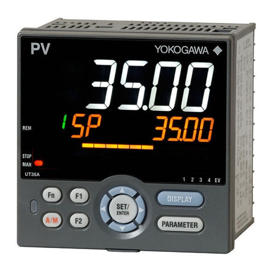
YOKOGAWA UT35A-L User Manual (150 pages)
Digital Indicating Controller (Limit Control Type)
Brand:
YOKOGAWA
| Category:
Controller
| Size: 8 MB
Table of Contents
Contents
4
Trademarks
5
Safety Precautions
5
Handling Precautions for the Main Unit
7
Checking the Contents of the Package
7
Model and Suffix Codes of UT35A-L
8
Symbols Used in this Manual
10
How to Use this Manual
11
Introduction
4
Notice
4
Target Readers
4
Chapter 15 Power Failure Recovery Processing / Power Frequency Setting
11
Table of Contents
12
Chapter 1 Introduction to Functions
16
Quick Setting Function
16
Input/Output Functions
17
Limit Control Functions
18
Display and Key Functions
20
Communication Functions
21
Definition of Main Symbols and Terms
23
Chapter 2 UT35A-L Operating Procedures
24
Chapter 3 Part Names
26
Names and Functions of Display Parts
26
Names and Functions of Keys
27
List of Display Symbols
29
Brief Description of Setting Details (Parameters)
31
Chapter 4 Basic Operation
32
Overview of Display Switch and Operation Keys
32
How to Set Parameters
35
Chapter 5 Quick Setting Function
40
Setting Using Quick Setting Function
40
Restarting Quick Setting Function
45
Chapter 6 Monitoring And Control Of Regular Operations
46
Monitoring and Control of Operation Displays
46
Operation Display Transitions
46
Setting Target Setpoint
49
Setting Alarm Setpoint
50
Releasing On-State (Latch) of Alarm Output
51
Chapter 7 Input (PV) Functions
52
Setting Functions of PV Input
52
Setting Input Type, Unit, Range, Scale, and Decimal Point Position
52
Setting Burnout Detection for Input
54
Setting Reference Junction Compensation (RJC) or External Reference Junction Compensation (ERJC)
55
Correcting Input Value
56
Chapter 8 Function Block Diagram
58
Chapter 9 Auxiliary Control Functions
60
Setting SP Limiter
60
Setting Controller Action at Power on (Restart Mode)
61
Chapter 10 Retransmission Output Functions
62
Setting Retransmission Output Terminal, Type, and Scales
62
Changing Current Output Range
63
Chapter 11 Alarm Functions
64
Setting Alarm Type
64
Setting Hysteresis to Alarm Operation
72
Delaying Alarm Output (Alarm Delay Timer)
73
Chapter 12 Contact Input Functions
74
Setting Contact Input Function
74
Chapter 13 Display, Key, And Security Functions
76
Setting Display Functions
76
Setting Active Color Pv Display Function
76
Masking Least Significant Digit Of Pv Display
79
Setting Economy Mode
80
Selecting the Initial Operation Display that Appears at Power on
80
Setting Message Function
81
Changing Guide Scroll Speed
82
Turning Guide Display ON/OFF
82
Setting Automatic Return to Operation Display
82
Assigning Function to User Function Key
84
Setting Security Functions
85
Setting a Password
85
Setting Parameter Display Level
85
Locking (Hiding) Parameter Menu Display
86
Key Lock
87
Prohibiting Writing Via Communication
87
Confirmation of Key and I/O Condition and Version
88
Confirmation of Key and I/O Condition
88
Confirmation Of Version
90
Chapter 14 Parameter Initialization
92
Initializing Parameter Settings to Factory Default Values
92
Registering and Initializing User Default Values
93
Registering As User Setting (Default) Values
93
Initializing To User Setting (Default) Values
93
Chapter 15 Power Failure Recovery Processing / Power Frequency Setting / Other Settings
94
Remedies if Power Failure Occurs During Operations
94
Power Frequency Setting
95
Chapter 16 Troubleshooting, Maintenance, and Inspections
96
Troubleshooting
96
Troubleshooting Flowchart
96
Errors During Operation
98
Maintenance
102
Cleaning
102
Packaging When Shipping the Product for Repair
102
Replacing Parts
102
Periodic Maintenance
103
Disposal
104
Chapter 17 Installation and Wiring
106
Installation Location
106
Mounting Method
108
External Dimensions and Panel Cutout Dimensions
109
Wiring
110
Important Information on Wiring
110
Pv Input Wiring
112
Limit Control Output (Relay) Wiring
113
Contact Input Wiring
114
Contact Output Wiring
115
Retransmission Output Wiring
116
Communication Interface Wiring
117
Ethernet Communication Interface Wiring
118
Power Supply Wiring
120
Attaching and Detaching Terminal Cover
121
Chapter 18 Parameters
122
Parameter Map
122
List of Parameters
127
Operation Parameters
127
Setup Parameters
129
Appendix Input And Output Table
146
Appendix 1 Input and Output Table
146
Revision Information
148
Advertisement
YOKOGAWA UT35A-L Operation Manual (11 pages)
Digital Indicating, Limit Control Type
Brand:
YOKOGAWA
| Category:
Controller
| Size: 3 MB
Table of Contents
Hardware Specifications
2
Terminal Wiring Diagrams
3
Intentionally Blank
4
Names and Functions of Display Parts
5
Setup Procedure
5
Quick Setting Function
5
Setting Alarm Setpoint
6
Function Block Diagram
8
Operation Parameters
9
Setup Parameters
9
Advertisement
Related Products
YOKOGAWA UT350
YOKOGAWA UTAdvanced UT35A
YOKOGAWA UT35A/RSP
YOKOGAWA UT351-A Series
YOKOGAWA UT351-0A
YOKOGAWA UT351-2A
YOKOGAWA UT351
YOKOGAWA UT350-01
YOKOGAWA UT32A/RSP
YOKOGAWA UT32A-D
YOKOGAWA Categories
Measuring Instruments
Test Equipment
Transmitter
Controller
Media Converter
More YOKOGAWA Manuals
Login
Sign In
OR
Sign in with Facebook
Sign in with Google
Upload manual
Upload from disk
Upload from URL