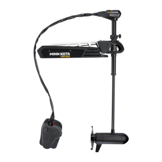
MINN KOTA FORTREX Installation Instructions Manual
Bow-mount trolling motor
Hide thumbs
Also See for FORTREX:
- Owner's manual (62 pages) ,
- User manual (22 pages) ,
- User manual (28 pages)
Table of Contents
Advertisement
Available languages
Available languages
Quick Links
Advertisement
Table of Contents

Related Manuals for MINN KOTA FORTREX


Summary of Contents for MINN KOTA FORTREX
- Page 1 FORTREX ® BOW-MOUNT TROLLING MOTOR Installation Instructions...
-
Page 2: Motor Information
THANK YOU Thank you for choosing Minn Kota. We believe that you should spend more time fishing and less time positioning your boat. That’s why we build the smartest, toughest, most intuitive trolling motors on the water. Every aspect of a Minn Kota trolling motor is thought out and rethought until it’s good enough to bear our name. -
Page 3: Safety Considerations
WARNING You are responsible for the safe and prudent operation of your vessel. We have designed your Minn Kota product to be an accurate and reliable tool that will enhance boat operation and improve your ability to catch fish. This product does not relieve you from the responsibility for safe operation of your boat. -
Page 4: Know Your Boat
KNOW YOUR BOAT Port Starboard Inboard Outboard Keel Port Starboard Gunwale Transom Stern Gunwale Stern Hull 4 | minnkotamotors.com ©2018 Johnson Outdoors Marine Electronics, Inc. -
Page 5: Installation
INSTALLING THE FORTREX Your new Fortrex comes with everything you’ll need to directly install it to the boat. This motor can be directly mounted to the boat or coupled with a Minn Kota quick release bracket for ease of mounting and removal. For installation with a quick release bracket, refer to the installation instructions provided with the bracket. -
Page 6: Assembly Of Motor To Mount
ASSEMBLY OF MOTOR TO MOUNT MOUNTING CONSIDERATIONS It is recommended that the motor be mounted as close to the keel or centerline of the boat as possible. Make sure the area under the mounting location is clear to drill holes and install View accessories nuts and washers. - Page 7 INSTALLING THE BOWGUARD Align the Keyways on the inside of the Bowguard Pull Grip and Rope with the End Links on the Mount. Lower the motor Allen Screw assembly straight down until seated. Lock Washer Install the 5/16” Allen Screw and the Lock Washer and tighten to 10-12 ft/lbs.
- Page 8 INSTALLING THE BOWGUARD ITEM(S) NEEDED #20 x 1 Review the mounting considerations at the beginning of the Installation section for proper placement. Place the Mount as close to the centerline or keel of the boat as possible, with the motor in the stowed Mount position, on the deck of the boat.
- Page 9 INSTALLING THE BOWGUARD Check the placement with the motor in the deployed position. When the motor is in the deployed position, make sure that the Shaft is 1-1/2" out past the Gunwale of the boat. The lower unit, when stowed and deployed must not encounter any obstructions.
-
Page 10: Installing The Gas Spring Pin
INSTALLING THE GAS SPRING PIN ITEM(S) NEEDED #6 x 6 #5 x 6 #4 x 6 Put a 1/4-20 x 2 1/2" Screw (Item #4) in each of the drilled locations. The Screw should pass through the Screw Mount Plate and the boat deck. Place a Flat Washer (Item #5) and then a Nylock Nut (Item #6) at the end of each screw as shown and secure. -
Page 11: Placing The Bow-Mount Stabilizer
The Bow-Mount Stabilizer is not required or Bowguard and reduce bouncing when the motor is stowed and included on the 80lb 45” Fortrex. transported. Attention to detail is needed for successful installation of the stabilizer. We recommend to have the stabilizer bracket installed by a qualified marine installer. - Page 12 Bowguard behind the spring. Secure with a 1/4” Allen Wrench. Tighten to 10 ft lb. NOTICE: The two Lock Washers (Item #16) are not used when installing on the Fortrex. 12 | minnkotamotors.com ©2018 Johnson Outdoors Marine Electronics, Inc.
- Page 13 PLACING THE BOW-MOUNT STABILIzER Measure the proper length of the Aluminum Rod by Stabilizer standing it, with the threaded end down, onto the Bracket deck surface so that it sits vertically right next to the Stabilizer Bracket. 3/4" Mark the Aluminum Rod with a pencil or marker 3/4" past the top of the Stabilizer Bracket.
- Page 14 MOUNTING THE FOOT PEDAL Once in the correct position, tighten the Jam Nut Top Bumper upwards against the Stabilizer Bracket. This will Stabilizer prevent the Aluminum Rod from turning. Bracket Install the Top Bumper if there are threads exposed Jam Nut on the Aluminum Rod above the Stabilizer Bracket.
- Page 15 IDENTIFYING TROLLING MOTOR FEATURES BY THEIR ASSOCIATED CABLES IDENTIFYING TROLLING MOTOR FEATURES BY THEIR ASSOCIATED CABLES Your trolling motor may be pre-installed with Built-In MEGA Down Pedal Control Sleeve Imaging OR Universal Sonar. These features require cables to be Connection Assembly from Control Head Cable connected to an output device.
- Page 16 ROUTING CONNECTION CABLES Identify where the Built-in MEGA Down Imaging or Universal Sonar Cable needs to be connected and route along an established routing system in your boat. Use cable ties to loosely secure cables if needed. Power Cables NOTICE: After the cable(s) exit(s) the Foot Foot Pedal Pedal, it should be routed through an established...
- Page 17 Built-In MEGA Down Imaging delivers nearly 3X the output of standard Side Imaging®, and takes fishfinding into the megahertz frequency for the very first time. The Minn Kota flagship families of trolling motors, including Ultrex, Ulterra, Terrova, and Fortrex, now include Built-In MEGA Down Imaging sonar, the clearest imaging available only from Humminbird.
- Page 18 FEATURE OVERVIEW AND CONNECTING THE CABLES When installing with a Solix, the Built-In MEGA Humminbird Solix Fish Finder Down Imaging cable can be plugged directly into the Solix fish finder. Plug the Built-in MEGA Down Imaging cable into the corresponding connection on the Solix fish finder.
- Page 19 FEATURE OVERVIEW AND CONNECTING THE CABLES Universal Sonar Your trolling motor may be pre-installed with a Universal Sonar transducer system. Universal Sonar is a 2D sonar transducer with a temperature sensor that is integrated into the lower unit of the trolling motor. It has an operating frequency of 83/200 kHz. Connecting this transducer to a compatible fish finder gives you a 2D sonar view of what is happening directly below your trolling motor.
- Page 20 If the cable length does not reach the desired fish finder installation location, a 14.5’ extension cable is Four Pin Connector available to purchase. Minn Kota recommends using the MKR-US2-11. Take the Universal Sonar Extension Cable, if needed, Locking Collar and attach it to the Universal Sonar Cable exiting the Foot Pedal.
-
Page 21: Installing The Prop
INSTALLING THE PROP INSTALLING THE PROP ITEM(S) NEEDED #7 x 1 #9 x 1 #10 x 1 #8 x 1 CAUTION Drive Pin Armature Shaft Disconnect the motor from the battery before beginning any prop work. Propeller Take the Drive Pin (Item #10) and slide it through the Hole in the Armature Shaft. -
Page 22: Battery & Wiring Installation
CAUTION These guidelines apply to general rigging to support your Minn Kota motor. Powering multiple motors or additional electrical devices from the same power circuit may impact the recommended conductor gauge and circuit breaker size. If you are using wire longer than that provided with your unit, follow the conductor gauge and circuit breaker sizing table below. -
Page 23: Selecting The Correct Batteries
Review your charger’s manual carefully or consult the manufacturer prior to use to ensure your charger is compatible. Minn Kota recommends using Minn Kota brand chargers to recharge the batteries connected to your Minn Kota trolling motor, as they have been engineered to work with motors that include a bonding wire. - Page 24 CONNECTING THE BATTERIES IN SERIES positive voltage into the “ground” of that accessory, which can cause excess corrosion. Any damage caused by incorrect connections between battery systems will not be covered under warranty. Automatic Jump Start Systems and Selector Switches Automatic jump start systems and selector switches tie the negatives of the connected batteries together.
- Page 25 Keep leadwire wing nut connections tight and solid to battery terminals. • Locate battery in a ventilated compartment. This completes the installation of your Fortrex. A complete Owner’s Manual can be downloaded at minnkotamotors.com. minnkotamotors.com | 25 ©2018 Johnson Outdoors Marine Electronics, Inc.
-
Page 26: Recommended Accessories
Stop buying new batteries and start taking care of the ones you’ve got. Many chargers can actually damage your battery over time – creating shorter run times and shorter overall life. Digitally controlled Minn Kota chargers are designed to provide the fastest charge that protect and extend battery life. - Page 27 FORTREX ® MOTEUR DE PÊCHE À LA TRAÎNE MONTÉ SUR ÉTRAVE Instructions d’installation...
-
Page 28: Numéro De Série
Pour le service : communiquer avec Minn Kota au (800) 227-6433; retourner le moteur au Centre de service de l’usine de Minn Kota; envoyer ou apporter le moteur à un centre de service agréé de Minn Kota. Une liste de centres de service agréés est disponible sur notre site Web, à... -
Page 29: Consignes De Sécurité
à la navigation et toujours exercer une veille permanente afin de pouvoir réagir au fur et à mesure que les situations se présentent. Vous devez toujours être prêt à reprendre le contrôle manuel de votre bateau. Apprenez à utiliser votre Minn Kota dans une zone exempte de dangers et d’obstacles. -
Page 30: Connaissez Votre Bateau
CONNAISSEZ VOTRE BATEAU Étrave Bâbord Tribord En-bord Hors-bord Quille Bâbord Tribord Plat-bord Tableau Arrière Stern Plat-bord Étrave Poupe Coque 30 | minnkotamotors.com ©2018 Johnson Outdoors Marine Electronics, Inc. -
Page 31: Installation
INSTALLATION DU FORTREX Votre nouveau Fortrex est offert avec tout ce dont vous aurez besoin pour le montage direct au bateau. Ce moteur peut être monté directement sur le bateau ou couplé avec un support à dégagement rapide Minn Kota pour un montage et un démontage simples. Pour l’installation avec un support à... - Page 32 électrique sur obstruction lorsqu’il est dans l’eau ou relevé. Envisagez l’installation d’un support à minnkotamotors.com. dégagement rapide ou un adaptateur. Pour la liste complète des accessoires Minn Kota, veuillez visiter minnkotamotors.com. OUTILS ET RESSOURCES NÉCESSAIRES • Tournevis cruciforme nº 2 •...
- Page 33 INSTALLATION DU PROTÈGE-PROUE Alignez les rainures de clavette sur l’intérieur du Poignée et corde de traction hexagonale protège-proue avec les liens d’extrémité sur le support. Abaissez l’ensemble du moteur jusqu’à ce qu’il soit assis. Rondelle de blocage Installez la vis hexagonale 5/16 po (7,94 mm) et la rondelle de blocage puis serrez entre 10 et 12 pi-lb (15,5 et 16,2 Nm) avec une clé...
- Page 34 INSTALLATION DU PROTÈGE-PROUE ARTICLE(S) REQUIS #20 x 1 Relisez les facteurs de montage au début de la section Installation pour savoir l’emplacement qui convient. Placez le support aussi près que possible de l’axe central ou de la quille du bateau, avec le moteur Support en position arrimée, sur le pont du bateau.
- Page 35 INSTALLATION DU PROTÈGE-PROUE Vérifiez l’emplacement avec le moteur en position déployée. Lorsque le moteur est en position déployée, veillez à ce que l’arbre dépasse le plat- bord de 1½ po (3,8 cm). L’appareil inférieur, lorsque arrimé et déployé, ne doit pas rencontrer d’obstacles. Vérifiez l’emplacement de la courroie de retenue lorsque le moteur est en position arrimée et déployée et ajustez, si nécessaire.
- Page 36 INSTALLER LA GOUPILLE DU RESSORT À GAz ARTICLE(S) REQUIS #6 x 6 #5 x 6 #4 x 6 Mettre une vis ¼-20 x 2½ po (0,635-20 x 63,5 mm) (article nº 4) dans chaque trou percé. La vis devrait traverser la plaque de support et le pont du bateau. Placez une rondelle plate (article nº...
-
Page 37: Placer Le Stabilisateur Du Support À L'étrave
Le stabilisateur sur proue n’est pas nécessaire ni stabiliser le protège-proue et pour réduire les rebonds lorsque le inclus dans le Fortrex de 45 po (114 cm) et 80 lb (36,3 kg). moteur est arrimé et transporté. Il faudra faire preuve de minutie pour réussir l’installation du stabilisateur. - Page 38 Les deux rondelles de blocage (article nº 16) ne protège-proue, derrière le ressort. Fixez avec une clé sont pas utilisées pour l’installation sur le Fortrex. hexagonale de ¼ po (6,35 mm). Serrez à un couple de 10 pi-lb (13,6 Nm).
- Page 39 PLACER LE STABILISATEUR DU SUPPORT À L’ÉTRAVE Mesurez la bonne longueur pour la tige en aluminium en mettant celle-ci debout, avec Ferrure du stabilisateur l’extrémité filetée pointant vers le bas, sur la surface du pont, de sorte qu’elle se trouve à la verticale juste ¾...
-
Page 40: Montage De La Pédale
MONTAGE DE LA PÉDALE Une fois dans la bonne position, serrez le contre- Pare-chocs écrou vers le haut contre la ferrure du stabilisateur. supérieur Cela empêchera la tige en aluminium de tourner. Ferrure du stabilisateur Installez le pare-chocs supérieur si une partie du Contre-écrou filetage est exposée sur la tige en aluminium au- dessus de la ferrure du stabilisateur... - Page 41 IDENTIFICATION DES CARACTÉRISTIQUES DU MOTEUR DE PÊCHE À LA TRAÎNE AU MOYEN DES CÂBLES QUI Y SONT ASSOCIÉS IDENTIFICATION DES CARACTÉRISTIQUES DU MOTEUR DE PÊCHE À LA TRAÎNE AU MOYEN DES CÂBLES QUI Y SONT ASSOCIÉS Votre moteur de pêche à la traîne pourrait être équipé du Ensemble du manchon de MEGA Down Imaging intégré...
- Page 42 ACHEMINEMENT DES CÂBLES DE CONNEXION Repérez l’endroit où le câble du MEGA Down Imaging intégré ou de l’Universal Sonar doit être connecté et acheminez-le le long d’un système d’acheminement établi sur votre bateau. Utilisez les attaches de câble pour fixer lâchement Câbles les câbles au besoin.
- Page 43 Le MEGA Down Imaging intégré est presque trois fois plus puissant que le Side Imaging® standard et amène la détection de poissons au niveau des fréquences mégahertz pour la première fois. Les gammes de moteurs de pêche à la traîne Minn Kota haut de gamme, dont Ultrex, Ulterra, Terrova et Fortrex, possèdent maintenant le sonar MEGA Down Imaging intégré, l’imagerie la plus nette offerte uniquement...
- Page 44 APERÇU DES CARACTÉRISTIQUES ET CONNEXION DES CÂBLES Lors d’une installation avec un Solix, vous pouvez Détecteur de poissons Humminbird Solix brancher directement le câble du MEGA Down Imaging intégré sur le détecteur de poissons Solix. Branchez le câble de MEGA Down Imaging intégré sur la connexion correspondante du détecteur de poissons Solix.
- Page 45 APERÇU DES CARACTÉRISTIQUES ET CONNEXION DES CÂBLES Universal Sonar Un système de transducteur Universal Sonar peut être préinstallé sur votre moteur de pêche à la traîne. Le Universal Sonar est un transducteur sonar 2D, doté d’un capteur de température intégré dans le module inférieur du moteur de pêche à la traîne. Il se caractérise par une fréquence de fonctionnement de 83/200 kHz.
- Page 46 Si le câble n’atteint pas l’emplacement d’installation désiré du détecteur Connecteur à quatre broches de poissons, vous pouvez acheter une rallonge de 14,5 pi (4,4 m). Minn Kota recommande d’utiliser le MKR-US2-11. Bague de blocage Si nécessaire, branchez la rallonge de l’Universal Sonar sur le câble de l’Universal Sonar provenant de...
-
Page 47: Installation De L'hélice
INSTALLATION DE L’HÉLICE INSTALLATION DE L’HÉLICE ARTICLE(S) REQUIS #7 x 1 #9 x 1 #10 x 1 #8 x 1 ATTENTION Arbre Ergot d’armature d’entraînement Débranchez le moteur de la batterie avant d’effectuer tout travail ou entretien sur l’hélice. Hélice Prenez l’ergot d’entraînement (article nº... -
Page 48: Installation Des Batteries Et Du Câblage
ATTENTION Ces lignes directrices s’appliquent au gréement général pour soutenir le moteur de Minn Kota. L’alimentation de multiples moteurs ou d’autres appareils électriques, à partir du même circuit d’alimentation, peut infl uer sur le gabarit de conducteurs et le dimensionnement des disjoncteurs recommandé. - Page 49 Utilisation de chargeurs-onduleurs Votre moteur de pêche à la traîne Minn Kota peut être conçu avec un fil de masse interne pour réduire les interférences avec d’autres sonars. La plupart des systèmes de charge alternateurs ne tiennent pas compte de ce fil de masse et connectent les bornes négatives des batteries du moteur de pêche à...
- Page 50 CONNEXION DES BATTERIES EN SÉRIE électrique étant donné que les interférences provenant du propulseur électrique sont inévitables. Lorsque vous connectez un accessoire supplémentaire à l’une des batteries du propulseur électrique, ou lorsque vous effectuez des connexions entre les batteries du propulseur électrique et d’autres systèmes de batterie sur le bateau, assurez-vous de respecter attentivement les indications ci-dessous.
- Page 51 Gardez le serrage des écrous de papillon de raccordement solide et bien serré autour des bornes de la batterie. • Installez la batterie dans un compartiment ventilé. L’installation de votre Fortrex est terminée. Un manuel complet du propriétaire peut être téléchargé à minnkotamotors.com. minnkotamotors.com | 51...
-
Page 52: Accessoires Recommandés
à la longue, pouvant entraîner une autonomie réduite et une durée de vie plus courte. Les chargeurs Minn Kota à commande numérique assurent une charge rapide pour une protection et une durée de vie prolongée.
Need help?
Do you have a question about the FORTREX and is the answer not in the manual?
Questions and answers