Table of Contents
Advertisement
Advertisement
Table of Contents

Related Manuals for MINN KOTA VANTAGE


Summary of Contents for MINN KOTA VANTAGE
- Page 1 VANTAGE TRANSOM-MOUNT TROLLING MOTOR USER MANUAL...
- Page 2 REMEMBER TO KEEP YOUR RECEIPT AND IMMEDIATELY REGISTER YOUR TROLLING MOTOR. NOTE: Do not return your Minn Kota motor to your retailer. Your retailer is not authorized to repair or replace this unit. You may obtain service by: calling Minn Kota; returning your motor to the Minn Kota Factory Service Center; sending or taking your motor to any Minn Kota authorized service center.
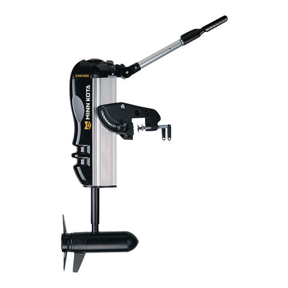
- Page 3 FEATURES Direction Indicator 4:1 Articulated Steering Power Trim Speed Control Digital Maximizer On/Off Tilt/Extend Tiller Handle Breakaway Mounting Bracket Clamp Screws Bracket Tension and Angle Adjustment Screw Cool, Quiet Power Motor Weedless Wedge 2 Propeller Specifications subject to change without notice. *This diagram is for reference only and may differ from your actual motor.
-
Page 4: Motor Installation
5. Adjust the handle to a comfortable position. NOTE: When mounted properly, the Vantage motor lower unit will be out of the water when the boat is on plane. If lower unit creates water spray when on plane, slightly re-adjust it higher until there is no more water spray. -
Page 5: Battery Wiring & Installation
CAUTION: These guidelines apply to general rigging to support your Minn Kota motor. Powering multiple motors or additional electrical devices from the same power circuit may impact the recommended conductor gauge and circuit breaker size. If you are using wire longer than that provided with your unit, follow the conductor gauge and circuit breaker sizing table below. -
Page 6: Selecting The Correct Batteries
Sizing Table” in the previous section to fi nd the appropriate circuit breaker or fuse for your motor. For motors requiring a 60-amp breaker, the Minn Kota MKR-19 60-amp circuit breaker is recommended. CONNECTING THE BATTERIES IN SERIES (IF REQUIRED FOR YOUR MOTOR) 24 VOLT SYSTEMS: 1. -
Page 7: Motor Wiring Diagram
MOTOR WIRING DIAGRAM 24 VOLT SYSTEM Coil Cord Coil Cord Leads Control Board On/Off Light Black Battery- Deploy Light Lift Lift Lift Motor Red Battery+ White Lift Lead Yellow Lead Black Lift Lead Red Motor+ Black Motor- BATTERY 2 BATTERY 1 MOTOR... - Page 8 MOTOR WIRING DIAGRAM 36 VOLT SYSTEM Coil Cord Coil Cord Leads Control Board On/Off Light Black Battery - Deploy Light Lift Lift Red Battery+ Lift Motor White Lift Lead Yellow Lead Black Lift Lead Red Motor+ Black Motor- Jumper Jumper MOTOR BATTERY 1 BATTERY 2...
-
Page 9: Using & Adjusting The Motor
USING & ADJUSTING THE MOTOR ADJUSTING THE DEPTH OF THE MOTOR To position the lower unit, press and release the DOWN button on the tiller to automatically lower the motor into the water. To adjust for shallow water, deploy the motor and hit the DOWN button a second time and the motor will stop at that point. - Page 10 USING & ADJUSTING THE MOTOR BACKTROLLING The orientation of the lower unit can be changed for backtrolling. Set your speed to 0 and trim the lower unit down to the fully deployed position. Slide the latch knob to the front and hold. Align the directional indicator with the tiller handle and slightly twist the indicator knob left or right while pulling up with slight force until the alignment is achieved and the indicator knob is free.
-
Page 11: Service And Maintenance
SERVICE & MAINTENANCE PROPELLER REPLACEMENT TOOLS AND RESOURCES REQUIRED: Propeller • Box End Wrench Slot End - 1/2” for motors with 70 lbs thrust or lower. - 9/16” for motors with 80 lbs thrust or higher. Prop Nut Washer • Screwdriver (optional) CAUTION: Disconnect the motor from the battery before beginning any prop work or... -
Page 12: Troubleshooting And Repair
If problems still persist, call our service department. ATTENTION: The lift system of the Vantage motor can be aff ected by cold temperatures. At temperatures below 32 degrees Farenheit., (0 degrees Celsius.), the lubricant in the lift system can become viscous preventing stow/deploy. Also, if this motor is being used in open water areas at freezing temperatures, ice can form on the telescoping portion of the motor shaft preventing stow/deploy. -
Page 13: Parts Diagram
101 LBS THRU - 36 VOLT This page provides Minn Kota® WEEE compliance disassembly instructions. For more information about where you should dispose of your waste equipment for recycling and recovery and/ or your European Union member state requirements, please contact your dealer or distributor from which your product was purchased. -
Page 14: Parts List
PARTS LIST VANTAGE 80/101 80/101 LBS THRU - 24/36 VOLT PART PART ITEM QTY DESCRIPTION ITEM QTY DESCRIPTION NUMBER NUMBER 421-276 IN END HOUSING 2053401 SCREW-10 X 1/2, T YPE 25 990-045 THRU SPACER 2353401 SCREW-10-16 X 1/2 ALGD 992-010... - Page 15 HER - F T (ZINC) 2050220 SHIELD-EXTRUSION 2053107 NUT-3/8-16, TOPLOCK 2053414 SCREW-#8-32 X 1/2” 2990921 HANDLE SEMBLY 2055611 L-SHIELD - VANTAGE 2884106 HANDLE RL BOARD/GRIP KIT (97,149) 2998200 CIRCUIT BRKR ASSEMBLY 36V 2994005 RL BOARD SY-HANDLE 2051732 HER .315 X .562...
-
Page 16: Environmental Compliance Statement
Minn Kota motors are not subject to the disposal regulations EAG-VO (electric devices directive) that implements the WEEE directive. Nevertheless never dispose of your Minn Kota motor in a garbage bin but at the proper place of collection of your local town council. -
Page 17: Recommended Accessories
Stop buying new batteries and start taking care of the ones you’ve got. Many chargers can actually damage your battery over time – creating shorter run times and shorter overall life. Digitally controlled Minn Kota chargers are designed to provide the fastest charge that protect and extend battery life.
Need help?
Do you have a question about the VANTAGE and is the answer not in the manual?
Questions and answers