Table of Contents
Advertisement
Advertisement
Table of Contents

Related Manuals for Lutron Electronics CL-2006


Summary of Contents for Lutron Electronics CL-2006
-
Page 2: Table Of Contents
TABLE OF CONTENTS 1. FEATURES..............1 2. SPECIFICATIONS............2 3. FRONT PANEL DESCRIPTION........4 3-1 Cover of Testing bottle......... 4 3-2 Container of Testing bottle........4 3-3 Display..............4 3-4 Hold Button ( Esc Button )........4 3-5 TEST/CAL Button..........4 3-6 Power Button............4 3-7 ZERO Button............4 3-8 REC Button ( MAX, MIN Button )...... -
Page 3: Features
1. FEATURES * The meter measures the Free and Total chlorine ( CL ) in the 0.00 to 3.50 ppm ( mg/L ). * The measuring method is an adaptation of the USEPA Method 330.5 for waste water and Standard Method 4500-Cl G for drinking water. -
Page 4: Specifications
2. SPECIFICATIONS Circuit Custom one-chip of microprocessor LSI circuit. Display LCD size : 41 mm x 34 mm Range Free chlorine ( CL ) : 0.00 to 3.50 ppm ( mg/L ). Total chlorine ( CL ) : 0.00 to 3.50 ppm ( mg/L ). Resolution 0.01 ppm ( mg/L ). - Page 5 Operating 0 to 50 ℃ Temperature Operating Less than 85% R.H. Humidity Power Supply DC 1.5 V battery ( UM4, AAA ) x 6 PCs, or equivalent. Power Current Stand by Approx. DC 4 mA. Testing Approx. DC 12 mA. Weight 320 g/0.70 LB.
-
Page 6: Front Panel Description
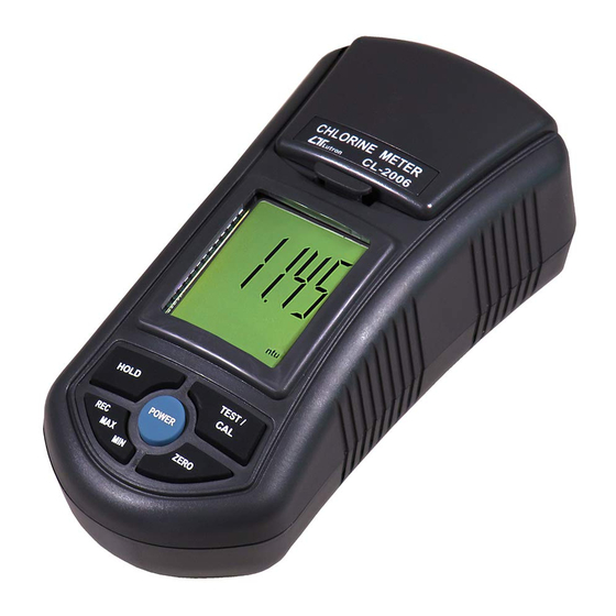
3. FRONT PANEL DESCRIPTION 3-1 Cover of Testing bottle 3-2 Container of Testing bottle 3-3 Display 3-4 Hold Button ( Esc Button ) 3-5 TEST/CAL Button 3-6 Power Button 3-7 ZERO Button 3-8 REC Button ( MAX, MIN Button ) 3-9 Battery Compartment/Cover 3-10 Free Chlorine 1.0 ppm standard solution. -
Page 7: Measuring Procedure
4. MEASURING PROCEDURE 4-1 Measurement Consideration White mark on the up position of " Testing Bottle " White mark on the edge of the " Container " Fig. 2 1) There is a " White mark " on the edge of the "... -
Page 8: Measurement
3) Insert the " Testing bottle " to the bottom of " Container " ( 3-2, Fig. 1 ) completely. 4) Before the measurement, it should envelop in the " Cover " ( 3-1, Fig. 1 ) completely. Remark : Before the measurement, it should keep the outside of Testing Bottle under the dry condition and without... - Page 9 3) Insert the " Testing bottle " to the bottom of " Container " ( 3-2, Fig. 1 ) completely. Before the measurement, it should envelop in the " Cover " ( 3-1, Fig. 1 ) completely. 4) Press " Zero Button " ( 3-7, Fig. 1 ) once, the display will show the text "...
-
Page 10: Free/Total Chlorine Mode Selection
6) Wait one minute approximately, then insert the " Testing bottle " to the bottom of " Container " ( 3-2, Fig. 1 ) completely. Before the measurement, it should envelop in the " Cover " ( 3-1, Fig. 1 ) completely. 7) Press "... -
Page 11: Data Hold
4-4 Data Hold During the measurement, press the " Hold Button " ( 3-4, Fig. 1 ) once will hold the measured value & the LCD will display a " HOLD " symbol. * Press the " Hold Button " once again will release the data hold function. -
Page 12: Calibration Procedure
5. CALIBRATION PROCEDURE 1) The meter can be calibrated under following calibration points : Free chlorine * Zero * 1.00 ppm Total chlorine * Zero * 1.00 ppm 2) The meter ship along with * Zero Chlorine standard solution ( CL-01 ) X 1 PC, * 1.0 ppm Free Chlorine standard solution ( CF-01 ) X 1 PC. - Page 13 Zero chlorine calibration * Insert the " Zero Chlorine standard solution into the " Container " ( 3-2 , Fig. 1) and envelope in the " Cover " ( 3-1, Fig. 1 ) completely, other procedures please refer to chapter 4-1, 4-2. * Press "...
- Page 14 * Press " CAL Button " ( 3-5, Fig. 1 ) once, the Display will show following text with flashing ( approx. 10 seconds ). flashing Then the Display will show : 1.00 Now the meter is finished the " Zero Chlorine " calibration procedures and ready for "...
- Page 15 * Insert the " 1.0 ppm standard solution into the " Container " ( 3-2 , Fig. 1) and envelope in the " Cover " ( 3-1, Fig. 1 ) completely, other procedures please refer to chapter 4-1, 4-2. Press " CAL Button " ( 3-5, Fig. 1 ) once, the Display will show following text with flashing ( approx.
-
Page 16: Battery Replacement
6. BATTERY REPLACEMENT 1) When the left corner of LCD display show " ", it is necessary to replace the battery. However, in-spec. measurement may still be made for several hours after low battery indicator appears before the instrument become inaccurate. 2) Loss the "...
Need help?
Do you have a question about the CL-2006 and is the answer not in the manual?
Questions and answers