Table of Contents
Advertisement
Quick Links
1,600 point data logger, RS232, AC/DC adapter
2,000 uS 20 mS, 100 mS, auto range, auto calibration
CONDUCTIVITY
METER
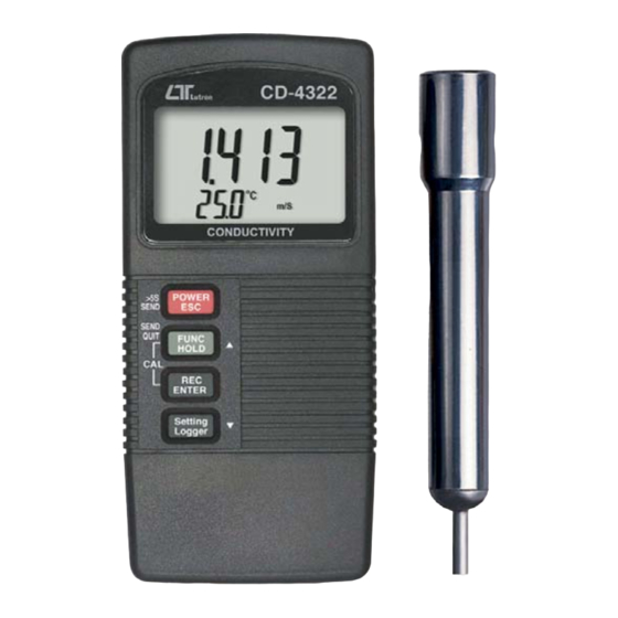
Model : CD-4322
OPERATION MANUAL
Your purchase of this
CONDUCTIVITY METER
marks a step forward for
you into the field of
precision measurement.
Although this METER is
a complex and delicate
instrument, its durable
structure
will
many years of use if
p r o p e r
o p e r a t i n g
t e c h n i q u e s
developed. Please read
t h e
f o l l o w i n g
instructions
and always keep this
manual
within
reach.
allow
a r e
carefully
easy
Advertisement
Table of Contents

Related Manuals for Lutron Electronics CD-4322


Summary of Contents for Lutron Electronics CD-4322
- Page 1 1,600 point data logger, RS232, AC/DC adapter 2,000 uS 20 mS, 100 mS, auto range, auto calibration CONDUCTIVITY METER Model : CD-4322 Your purchase of this CONDUCTIVITY METER marks a step forward for you into the field of precision measurement.
-
Page 2: Table Of Contents
TABLE OF CONTENTS 1. FEATURES............... 1 2. SPECIFICATIONS............. 2 3. FRONT PANEL DESCRIPTION..........4 3-1 Display..............4 3-2 Power/ESC/Send button..........4 3-3 FUNC/HOLD button ( Send quit/ button )....▲ 3-4 REC/Enter button............4 3-5 Setting/Logger button ( button )......▼ 3-6 Probe input socket............4 3-7 DC 9V adapter socket.......... -
Page 3: Features
1. FEATURES * * 3 measurement range, 2,000 uS, 20 mS, 100 mS with auto range. * Function : Conductivity, TDS. * Separate probe, easy for operation of different measurement environment. * Automatic temperature compensation range : 0 to 50 ℃... -
Page 4: Specifications
2. SPECIFICATIONS Display LCD size : 44 mm x 29 mm. Dual function LCD Circuit Custom one-chip of microprocessor LSI circuit. Function : Conductivity, TDS. Conductivity range : Ranges and Resolution 2000 uS/20.00 mS/100 mS. Conductivity resolution : * three ranges 1 uS/0.01 mS/0.1 mS. - Page 5 Data Hold Freeze the display reading. Sampling Time Approx. 1 second. of display Data Output RS 232/USB PC serial interface. * Connect the optional RS232 cable UPCB-02 will get the RS232 plug. * Connect the optional USB cable USB-01 will get the USB plug. Operating 0 to 50 ℃...
-
Page 6: Front Panel Description
3. FRONT PANEL DESCRIPTION Fig. 1... -
Page 7: Display
Fig. 2 Fig. 2 3-1 Display 3-2 Power/ESC/Send button 3-3 FUNC/Hold button ( Send quit/ button ) ▲ 3-4 REC/Enter button 3-5 Setting/Logger button ( button ) ▼ 3-6 Probe input socket 3-7 DC 9V adapter socket 3-8 RS-232 output terminal 3-9 Battery compartment/Cover 3-10 Battery cover screws 3-11 Probe Handle... -
Page 8: Measuring Procedure
4. MEASURING PROCEDURE 4-1 Conductivity measurement 1) Turn on the meter by pressing the " Power Button " ( 3-2, Fig. 1 ) momentarily. * Press the " Power Button " ( 3-2, Fig. 1 ) momentarily again will turn off the meter. Connect the "... -
Page 9: Tds Measurement
When make the measurement should immerse the " Sensing Electrode " immersed wholly into the measured solution. 4-2 TDS measurement 1) During the above 4-1 Conductivity measurement, if press the " Hold button " ( 3-3, Fig. 1 ) continuously at least two seconds will enter into the function of TDS measurement with default, the display will show as : xx,x ℃... -
Page 10: Data Hold
4-3 Data Hold During the measurement, press the " Hold button " ( 3-3, Fig. 1 ) once will hold the measured value & the LCD will display a " HOLD " symbol. * Press the " Hold button " once again will release the data hold function. - Page 11 The data logger procedures are following : a) Press the " REC button " ( 3-4, Fig. 1 ) once to start the Data record function and there will be a " REC " symbol on the display. b) Auto Data Logger ( Sampling time should select to 1, 2, 5, 10, 30, 60, 600, 1800 or 3600 seconds ) Press the "...
- Page 12 5. ADVANCED SETTING PROCEDURES Before executing Advanced Setting Procedures, exit the " Hold function " and the " Record " function first. * Press " Setting button " continuously at least 5 seconds to enter the setting function. * After already set the desiring value ( function ), press the "...
-
Page 13: Temp. Compensation Factor Setting
5-1 Temp. compensation factor Setting. ( Lower display show " SEt " ) After the low display show " SEt ", press the " Enter button " ( 3-4, Fig. 1 ) once. the " SEt " symbol will flash, the up display will show the "... -
Page 14: Auto Power On/Off
5-3 Auto power On/Off ( Lower display show " OFF " ) a. Use " button " ( 3-3, Fig. 1 ) to select " YES " or " no ". ▲ * YES : Auto power off. * no : Auto power disable, it is the manual power off. b. -
Page 15: Clear The Existing Saving Data From The Memory
5-6 Clear the existing saving data from the memory ( Lower display show " CLr " ) a. Use " button " ( 3-3, Fig. 1 ) to select " YES " or " no ". ▲ * YES : It will execute the memory clear function.. * no : It will be not to clear the memory. - Page 16 3) Push the " Send button " ( 3-2, Fig. 1 ) once, the lower display will show " SEnd ", the upper no. will count up until reach the data logger storage no., at the same the storage data logger data will send out the meter from the "...
-
Page 17: Rs232 Pc Serial Interface
7. RS232 PC SERIAL INTERFACE The instrument has RS232 PC serial interface via a 3.5 mm terminal ( 3-8, Fig. 1 ). The data output is a 16 digit stream which can be utilized for user's specific application. A RS232 lead with the following connection will be required to link the instrument with the PC serial port. - Page 18 Each digit indicates the following status : Start Word When send the upper display data = 1 When send the lower display data = 2 D12 & D11 Annunciator for Display = 01 = 02 ℃ ℉ uS = 13 mS = 14 Polarity 0 = Positive 1 = Negative...
-
Page 19: Battery Replacement
8. BATTERY REPLACEMENT 1) When the upper left corner of LCD display show " ", it is necessary to replace the battery. However, in-spec. measurement may still be made for several hours after low battery indicator appears before the instrument become inaccurate. - Page 20 4) a. Press the " Hold button " ( 3-3, Fig. 1 ) once, the " Display " ( 3-1, Fig. 1 ) will show the " Hold " indicator, then following press the " REC button " ( 3-4, Fig. 1 ) once, the Display will show : b.
-
Page 21: Optional Accessories
5) After the upper display already adjust to the value of " Conductivity Standard Solution ", release the fingers from the buttons. After a while the upper display will show the text " SAVE " and " End " then return to normal display. The calibration procedures are finished, the calibration value will save into the memory circuit. - Page 22 1.413 mS Conductivity Standard Solution CD-14 RS232 cable * Isolated RS232 cable. UPCB-02 * Used to connect the meter to the computer RS232 cable * USB Computer interface cable. USB-01 * Isolated USB cable. Data Logger * Software the used to download software the data logger ( data recorder ) SW-DL2005...
Need help?
Do you have a question about the CD-4322 and is the answer not in the manual?
Questions and answers