Table of Contents
Advertisement
4-20 mA
Controller/Alarm
Indicator
Model : CT-2012
Your purchase of this 4 to 20 mA CONTROLLER marks a
step forward for
measurement.
delicate instrument, its durable structure will allow many
years
of
developed.
carefully and always keep this manual within easy reach.
OPERATION MANUAL
you
Although this METER is a complex and
use
if
proper
Please
read
into the field of
operating
the
following
precision
techniques
are
instructions
Advertisement
Table of Contents

Subscribe to Our Youtube Channel
Related Manuals for Lutron Electronics CT-2012


Summary of Contents for Lutron Electronics CT-2012
- Page 1 4-20 mA Controller/Alarm Indicator Model : CT-2012 Your purchase of this 4 to 20 mA CONTROLLER marks a step forward for into the field of precision measurement. Although this METER is a complex and delicate instrument, its durable structure will allow many...
- Page 2 Caution Symbol Caution : * Risk of electric shock ! Caution : * Do not use fingers or any tool to touch the Wire Terminals. * Do not apply the relay contact load current > 0.5 Amp. * The instrument contains no user serviceable parts and should not be opened by the user.
-
Page 3: Table Of Contents
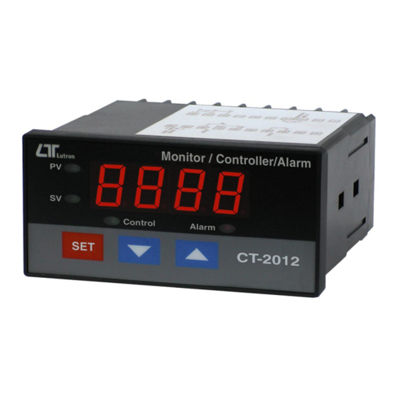
TABLE OF CONTENTS 1. FEATURES................. 2. SPECIFICATIONS..............3. FRONT PANEL DESCRIPTION..........3-1 Display..............5 3-2 PV ( process value ) indicator..........3-3 SV ( set value ) indicator..........3-4 Set Button.............. 5 ▼ Button.............. ▲ Button............. 3-7 Control relay indicator........... 5 3-8 Alarm relay indicator.......... -
Page 4: Features
* When CT-2012 cooperate LUTRON's 4 to 20 mA transmitters ( or any other transmitters if it build 4 to 20 mA output signal ), whole system will become the... -
Page 5: Specifications
2. SPECIFICATIONS Display * 4 digits red LED, 14 mm ( 0.55 inch ) digit height * 4 indicators : PV ( process value ) indicator SV ( set value ) indicator Control out indicator Alarm out indicator * According the 4-20 mA input signal, user can preset the desire display value between -1999 to 9999 ( decimal point can select to DP1, DP2, DP3 ). - Page 6 * Gain adjustment. * RS232 output unit code setting Default of internal function : Without advice previously, the function of CT-2012 will preset : * 4 mA = 0, 20 mA = 9999. * High control mode. * High alarm mode.
- Page 7 Power Supply 90 to 260 ACV, 50/60 Hz. Power Approx. 3.5 VA/AC 110V. Consumption Approx. 4.9 VA/AC 220V. Weight 384 g/ 0.84 LB. Dimension DIN size : 96 x 48 mm. Panel cut size : 92 mm x 46 mm. Depth : 110 mm.
-
Page 8: Front Panel Description
3. FRONT PANEL DESCRIPTION Fig. 1 3-1 Display 3-2 PV ( process value ) indicator 3-3 SV ( set value ) indicator 3-4 Set Button ▼ Button ▲ Button 3-7 Control relay indicator 3-8 Alarm relay indicator 3-9 Wire terminals 3-10 Case holder 3-11 RS232 terminal... -
Page 9: Measuring Procedure
4. MEASURING PROCEDURE 4-1 Terminal connection 1) Input the ACV power ( 90 to 260 ACV ) to T1, T2. Do not input the over voltage to the AC input terminals. 2) Connect the " Control Relay " output from T3, T4. Connect the "... -
Page 10: 1St Layer Setting Procedures
4-2 1st layer setting procedures CtLo Control Low limit value setting CtHi Control High limit value setting ALLo Alarm Low limit value setting ALHi Alarm High limit value setting a. Control Low limit value setting 1) Press the " Set Button " ( 3-4, Fig. 1 ) once, the "... -
Page 11: Alarm Low Limit Value Setting
Remark : * When adjust the value, the " SV indicator " ( 3-3, Fig. 1 ) will light. * The function of " Control High limit value " setting, refer to page 11, Fig. 3. c. Alarm Low limit value setting 1) After finish above "... -
Page 12: 2Nd Layer Setting Procedures
4-3 2nd layer setting procedures dPSt Point position setting 4 mA value setting 20-A 20 mA value setting FiLt Digital filter setting CtHy Control hysteresis value setting ALHy Alarm hysteresis value setting oFSt Offset value setting GAin Gain value setting Unit RS232 output unit code setting a. -
Page 13: 20 Ma Value Setting
Remark : * During adjust the value, the " SV indicator " ( 3-3, Fig. 1 ) will light. c. 20 mA value setting 1) After finish the " 4 mA value setting", press the " Set Button " ( 3-4, Fig. 1 ) once, the " Display " will show "... - Page 14 e. Control hysteresis value setting 1) After finish the " Digital filter value setting ", press the '" Set Button " ( 3-4, Fig. 1 ) once, the " Display " will show CtHy ", now the meter is ready for the "...
- Page 15 f. Alarm hysteresis value setting 1) After finish the " Control Hysteresis value setting " , press the " Set Button " ( 3-4, Fig. 1 ) once, the " Display " will show " ALHy ", now the meter is ready for the "...
-
Page 16: Offset Value Adjustment
g. Offset value adjustment 1) After finish the " Alarm hysteresis value setting " , press the " Set Button " ( 3-4, Fig. 1 ) once, the " Display " will show " oFSt ", now the meter is ready for the " Offset value adjustment "... -
Page 17: Rs232 Output Unit Code Setting
i. RS232 output unit code setting 1) After finish the " Gain value setting " , press the " Set Button " ( 3-4, Fig. 1 ) once, the " Display " will show " Unit ", now the meter is ready for the the "... - Page 18 The 16 digits data stream will be displayed in the following format : D15 D14 D13 D12 D11 D10 D9 D8 D7 D6 D5 D4 D3 D2 D1 D0 Each digit indicates the following status : Start Word When send the upper display data = 1 When send the lower display data = 2 D12 &...
- Page 19 The RS232 output code list 00 = NO UNIT 33 = KHz 66 = mF 01 = C 34 = DCV 67 = MHz 02 = F 35 = DCuA 68 = uH 03 = % 36 = DCA 69 = dBm 04 = %RH 37 = DCmA 70 = Red...
-
Page 20: System Reset
6. SYSTEM RESET Power on the meter, use the two fingers to press " Set ▼ Button " ( 3-4, Fig. 1 ) and " Button " ( 3-7, Fig. 1 ) continuously more than 5 seconds until the Display show the text " rSt ", release the buttons. After "...
Need help?
Do you have a question about the CT-2012 and is the answer not in the manual?
Questions and answers