Table of Contents
Advertisement
SD card real time data logger
TDS ( Total dissolved solids ), Salt
'20 uS/200 uS/2 mS/20 mS/200 mS
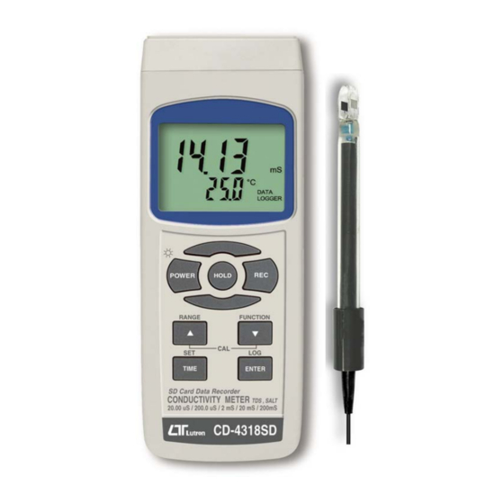
CONDUCTIVITY METER
Model : CD-4318SD
OPERATION MANUAL
Your purchase of this
CONDUCTIVITY METER
w i t h
S D
DATA LOGGER marks a
step forward for you
into
the
precision measurement.
Although this meter a
complex
and
instrument, its durable
structure
will
many years of use if
p r o p e r
o p e r a t i n g
t e c h n i q u e s
developed. Please read
t h e
f o l l o w i n g
instructions
and always keep this
manual
within
reach.
C A R D
field
of
delicate
allow
a r e
carefully
easy
Advertisement
Table of Contents

Related Manuals for Lutron Electronics CD-4318SD


Summary of Contents for Lutron Electronics CD-4318SD
- Page 1 SD card real time data logger TDS ( Total dissolved solids ), Salt '20 uS/200 uS/2 mS/20 mS/200 mS CONDUCTIVITY METER Model : CD-4318SD Your purchase of this CONDUCTIVITY METER w i t h C A R D DATA LOGGER marks a...
-
Page 2: Table Of Contents
TABLE OF CONTENTS 1. FEATURES..................1 2. SPECIFICATIONS................ 2-1 General Specifications..............2 2-2 Electrical Specifications................ 3. FRONT PANEL DESCRIPTION................. 4. FUNCTION SELECTION............... 7 5. CONDUCTIVITY/TDS MEASURING and CALIBRATION PROCEDURE..............5-1 Conductivity measurement............8 5-2 TDS ( PPM ) measurement..........5-3 Calibration................9 6. -
Page 3: Features
1. FEATURES * One meter for multi purpose operation : Conductivity, TDS ( Total dissolved solids ), Salt measurement. * Conductivity : 20 uS/ 200 uS/2 mS/20 mS/200 mS. * Salt : 0 to 12 % salt ( % weight ). * Conductivity measurement can select Temp. -
Page 4: Specifications
2. SPECIFICATIONS 2-1 General Specifications Circuit Custom one-chip of microprocessor LSI circuit. Display LCD size : 52 mm x 38 mm LCD with green backlight ( ON/OFF ). Measurement * Conductivity ( uS, mS ) Function * TDS ( Total Dissolved Solids, PPM ) * Salt ( % Weight ) * Temperature ( ℃,℉) Automatic from 0 to 60 ℃... - Page 5 Sampling Time Approx. 1 second. of Display Data Output RS 232/USB PC computer interface. * Connect the optional RS232 cable UPCB-02 will get the RS232 plug. * Connect the optional USB cable USB-01 will get the USB plug. 0 to 50 ℃. Operating Meter 0 to 60 ℃.
-
Page 6: Electrical Specifications
Optional * 1.413 mS Conductivity Standard Accessories Solution........ CD-14 SD memory card ( 2 GB ) AC to DC 9V adapter. USB cable, USB-01. RS232 cable, UPCB-02. Data Acquisition software,SW-U801-WIN. 2-2 Electrical Specifications (23±5 ℃ ℃ ℃ ℃ ) Conductivity ( uS, mS ) Range Measurement Resolution... - Page 7 Temperature Function Measuring Range Resolution Accuracy ℃ 0 ℃ to 60 ℃ 0.1 ℃ ±0.8 ℃ ℉ 32 ℉ to 140 ℉ 0.1 ℉ ±1.5 ℉ * @ 23±5℃ Salt Measurement 0 to 12 % salt ( % weight ). Range Resolution 0.01 % salt.
-
Page 8: Front Panel Description
3. FRONT PANEL DESCRIPTION Fig.1 3-1 Display 3-2 Power Button ( Backlight Button ) 3-3 Hold Button 3-4 REC Button 3-5 Range Button ( ▲ Button ) 3-6 Function Button ( ▼ Button ) 3-7 Time Button (SET Button) 3-8 Enter Button ( Logger Button ) 3-9 Stand 3-10 Battery Compartment/Cover 3-11 Battery Cover Screw... -
Page 9: Function Selection
4. FUNCTION SELECTION 1) Power ON the meter by pressing and holding the " Power Button " ( 3-2, Fig. 1 )for at least 1.5 seconds . Pressing the " Power Button " ( 3-2, Fig. 1 ) continuously and > 1.5 seconds again will turn off the meter. -
Page 10: Conductivity/Tds Measuring And Calibration Procedure
5. CONDUCTIVITY/TDS MEASURING and CALIBRATION PROCEDURE The meter default function are following : * The display unit is set to conductivity ( uS, mS ). * The temperature unit is set to ℃. * Temp. compensation factor is set to 2.0% per C. * Auto range. -
Page 11: Tds ( Ppm ) Measurement
Change the Temp. unit to ℉ ℉ ℉ ℉ If intend to change the Temp. unit from ℃ to ℉, please refer to chapter 10-7 page 23. Change the Temp. Coefficient Factor The default Temp. compensation factor value of the measurement solution is to 2.0% per ℃. - Page 12 3) Power on the meter by pressing " Power Button " ( 3-2, Fig. 1 ) once. 4) Hold the " Probe Handle " ( 3-18, Fig. 1) by hand and let the " Sensing head " ( 3-19, Fig. 1 ) immersed wholly into the measured solution.
- Page 13 Temprature Calibration 1) Install the " Probe Plug " ( 3-20, Fig. 1 ) into the " CD Socket " ( 3-13, Fig. 1 ). 2) Power on the meter by pressing " Power Button " ( 3-2, Fig. 1 ) once. 3) Hold the "...
-
Page 14: Salt Measuring And Calibration Procedure
6. SALT MEASURING and CALIBRATION 6-1 Salt measurement 1) Prepare the Probe ( CDPB-04, same probe as the conductivity measurement, refere to Fig. 1, page 6 ), install the " Probe Plug " ( 3-20, Fig. 1 ) into the " Probe Socket "... -
Page 15: Other Function
7. OTHER FUNCTION 7-1 Data Hold During the measurement, press the " Hold Button " ( 3-3, Fig. 1 ) once will hold the measured value & the LCD will display a " HOLD " symbol. Press the " Hold Button " once again will release the data hold function. -
Page 16: Lcd Backlight On/Off
7-3 LCD Backlight ON/OFF After power ON, the " LCD Backlight " will light automatically. During the measurement, press the " Backlight Button " ( 3-2, Fig. 1 ) once will turn OFF the " LCD Backlight ". Press the " Backlight Button " once again will turn ON the "... - Page 17 a. Start the datalogger Press the " LOG Button ( 3-8, Fig. 1 ) > 1.5 seconds continuously, the LCD will show the text of " LOGGER " indecator and flashing per sampling time, at the same time the measuring data along the time information will be saved into the memory circuit.
-
Page 18: Manual Datalogger ( Set Sampling Time = 0 Second )
second ) a. Set sampling time is to 0 second Press the " LOG Button ( 3-8, Fig. 1 )>1.5 second, the LCD will show the indecator " LOGGER " and " Position no. " symbol then press the " LOG Button " ( 3-8, Fig. 1 ) once , the "... -
Page 19: Sd Card Data Structure
1) When the SD card is used into the meter, the SD card When the first time, the SD card is used into the meter, the SD card will generate a route : CDB01 2) If the first time to execute the Datalogger, under the route CDB01\, will generate a new file name CDB01001.XLS. -
Page 20: Saving Data From The Sd Card To The Computer
9. Saving data from the SD card to the computer ( EXCEL software ) 1) After execute the Data Logger function, take away the SD card out from the " SD card socket " ( 3-17, Fig. 1 ). 2) Plug in the SD card into the Computer's SD card slot ( if your computer build in this installation ) or insert the SD card into the "... - Page 21 EXCEL data screen/graphic screen ( for example ) EXCEL graphic screen ( for example, graphic )
-
Page 22: Advanced Setting
10. ADVANCED SETTING Under do not execute the Datalogger function, press the " SET Button " ( 3-7, Fig. 1 ) continuously at least two seconds will enter the " Advanced Setting " mode. then press the " SET Button " ( 3-7, Fig. 1 ) once a while in sequence to select the eight main function, the display will show : DATE...... - Page 23 The adjusted value will be flashed. 2) After set all the time value ( Year, Month, Date, Hour, Minute, Second ), press the " SET Button " ( 3-7, Fig. 1 ) once will save the time value, then the screen will jump to Sampling time "...
- Page 24 ( 3-6, Fig. 1 ) to select the upper value to "YES " or "NO ". YES - Auto Power Off management will enable. NO - Auto Power Off management will disable. 2) After select the upper text to " YES " or " NO ", press the "...
- Page 25 1) Use the " ▲ Button " ( 3-5, Fig. 1 ) or " ▼ Button " ( 3-6, Fig. 1 ) to select the upper text to " USA " or " EURO". USA - Use " . " as the Decimal point with default. EURO - Use "...
- Page 26 C - Temperature unit is ℃ ℃ ℃ ℃ F - Temperature unit is ℉ ℉ ℉ ℉ 2) After Display unit is selected to " C " or " F ", press the " Enter Button " ( 3-8, Fig. 1 ) will save the setting function with default.
-
Page 27: Power Supply From Dc Adapter
11. POWER SUPPLY from DC ADAPTER The meter also can supply the power supply from the DC 9V Power Adapter ( optional ). Insert the plug of Power Adapter into " DC 9V Power Adapter Input Socket " ( 3-14, Fig. 1 ). The meter will permanent power ON when use the DC ADAPTER power supply ( The power Button function is disable ). -
Page 28: Rs232 Pc Serial Interface
14. RS232 PC SERIAL INTERFACE The instrument has RS232 PC serial interface via a 3.5 mm terminal ( 3-16, Fig. 1 ). The data output is a 16 digit stream which can be utilized for user's specific application. A RS232 lead with the following connection will be required to link the instrument with the PC serial port. - Page 29 The 16 digits data stream will be displayed in the following format : D15 D14 D13 D12 D11 D10 D9 D8 D7 D6 D5 D4 D3 D2 D1 D0 Each digit indicates the following status : Start Word When send the upper display data = 1 When send the lower display data = 2 D12, D11 Annunciator for Display...
-
Page 30: Optional Accessories
15. OPTIONAL ACCESSORIES Mmory card SD memory card ( 1 GB ) SD memory card ( 2 GB ) RS232 cable * Computer interface cable. UPCB-02 * Used to connect the meter to the computer ( COM port ). USB cable * Computer interface cable. -
Page 31: Patent
16. PATENT The meter ( SD card structure ) already get patent or patent pending in following countries : Germany Nr. 20 2008 016 337.4 JAPAN 3151214 TAIWAN M 358970 M 359043 CHINA ZL 2008 2 0189918.5 ZL 2008 2 0189917.0 Patent pending 1305-CD4318SD...
Need help?
Do you have a question about the CD-4318SD and is the answer not in the manual?
Questions and answers