
Subscribe to Our Youtube Channel
Related Manuals for JAI SP-20000M-PMCL


Summary of Contents for JAI SP-20000M-PMCL
- Page 1 Spark Series User Manual SP-20000M-PMCL SP-20000C-PMCL 20M CMOS Digital Progressive Scan Monochrome and Color Camera Document Version: Ver.1.6 SP-20000-PMCL_Ver.1.6_June2014 1045J-1304...
- Page 2 JAI Ltd., Japan and may only be used by the purchasers of the product. JAI Ltd., Japan makes no warranty for the use of its product and assumes no responsibility for any errors which may appear or for damages resulting from the use of the information contained herein.
- Page 3 SP-20000M-PMCL Supplement The following statement is related to the regulation on “ Measures for the Administration of the control of Pollution by Electronic Information Products “ , known as “ China RoHS “. The table shows contained Hazardous Substances in this camera.
- Page 4 SP-20000C-PMCL Supplement The following statement is related to the regulation on “ Measures for the Administration of the control of Pollution by Electronic Information Products “ , known as “ China RoHS “. The table shows contained Hazardous Substances in this camera. mark shows that the environment-friendly use period of contained Hazardous Substances is 15 years.
-
Page 5: Table Of Contents
SP-20000M-PMCL / SP-20000C-PMCL Contents Before using this camera ..............- 6 - General ..................- 7 - Camera composition ..............- 7 - 3. Main features ................- 8 - 4. Locations and functions ..............- 9 - 4.1 Locations and functions ..................- 9 - Rear Panel .................... - Page 6 LUT Index ..................... - 77 - 8.3.3 LUT Value ..................... - 77 - Gamma...................... - 78 - Shading Correction ..................- 78 - Blemish compensation ................... - 79 - ALC ......................- 80 - HDR function (SP-20000M-PMCL only) ..............- 81 - - 4 -...
- Page 7 Transport Layer Control ................- 95 - 2.4.10 User Set Control ..................- 96 - 2.4.11 JAI Custom ..................- 96 - Appendix 2 .................. - 112 - 1. Precautions ....................- 112 - 2. Typical Sensor Characteristics ................- 113 - 3.
-
Page 8: Before Using This Camera
All controllable functions are stored in the camera’s XML file. The JAI SDK can be downloaded from www.jai.com . A camera control tool for using the Short ASCII command protocol is not available on the JAI website. Please contact your local JAI representative if this is required. -
Page 9: General
They also provide a new HDR (High Dynamic Range) function. The latest version of this manual can be downloaded from: www.jai.com The latest version of the JAI SDK for the SP-20000M-PMCL and SP-20000C-PMCL can be downloaded from: www.jai.com For camera revision history, please contact your local JAI distributor. -
Page 10: Main Features
Vertical and horizontal binning on monochrome model Supports ROI (Region Of Interest) modes for faster frame rate 0dB to +24dB gain control for both SP-20000M-PMCL and SP-20000C-PMCL 304 μs (1/3290) to 8 seconds exposure control in 1 μs step ... -
Page 11: Locations And Functions
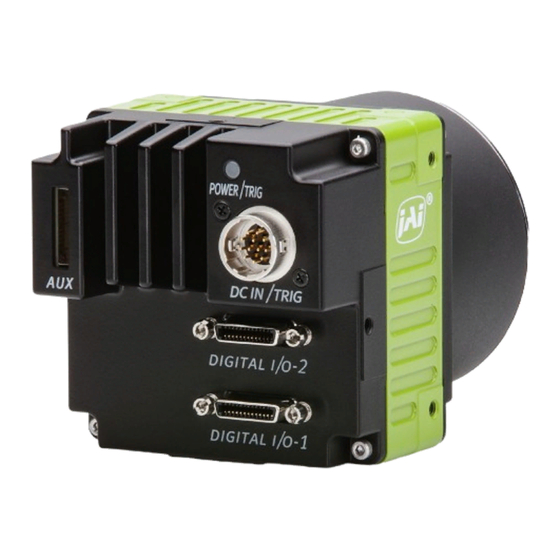
SP-20000M-PMCL / SP-20000C-PMCL 4. Locations and functions 4.1 Locations and functions Lens mount F-mount (Note *1) 10-pin connector AUX connector for TTL IN/OUT and LVDS IN LED Indication for power and Trigger input 12-pin connector DC+12V and Trigger input ... -
Page 12: Rear Panel
SP-20000M-PMCL / SP-20000C-PMCL Rear Panel The rear panel mounted LED provides the following information: Amber: Power connected – initiating This light goes OFF after initiating. Steady green: Camera is operating in Continuous mode Flashing green: The camera is receiving external triggering ... -
Page 13: Input And Output
SP-20000M-PMCL / SP-20000C-PMCL 5. Input and output Connectors and pin assignment 5.1.1 12-Pin connector 5.1.1.1 Figure Type: HR-10A-10R-12PB(72) Hirose male or equivalent Use the part number HR10A-10P-12S or equivalent for the cable side. Fig.3 Hirose 12-pin connector 5.1.1.2 Pin Assignment Table 1 12-pin configuration Pin no. -
Page 14: Pin Assignment
SP-20000M-PMCL / SP-20000C-PMCL 5.1.2.2 Pin assignment Table-2 Camera link pin configuration – connector 1 Pin No In/Out Name Note 1,26 Power Power 2(-),15(+) X_OUT0 3(-),16(+) X_OUT1 Data output 4(-),17(+) X_OUT2 5(-),18(+) X_Clk Clock for CL 6(-),19(+) X_OUT3 Data output 7(+),20(-) -
Page 15: Camera Link Interface
SP-20000M-PMCL / SP-20000C-PMCL Camera Link interface 5.2.1 Camera Link Interface Table-4 Camera Link interface SP-20000M/C-PMCL Camera Link Configuration Base Medium Full 80bit Port Camera Link port/bit 2Tap / 10bit 4Tap / 10bit 8 Tap / 8bit 8 Tap / 10bit... -
Page 16: Camera Link Pixel Clock
Camera Link interface. FVAL is only output via Digital I/O-1 connector. 5.2.2 Camera Link Pixel clock The SP-20000M-PMCL and SP-20000C-PMCL use the Camera Link pixel clock of 80 MHz as the default setting. It can be changed. Table – 5... -
Page 17: Digital In/Out Inteface
SP-20000M-PMCL / SP-20000C-PMCL Digital IN/OUT Inteface In the SP-20000M-PMCL and SP-20000C-PMCL, the software control tool can assign the necessary signals used in the system to digital inputs and outputs. 5.3.1 Line Selector In the Line Selector, the following input and output signals can be assigned. -
Page 18: Line Format
SP-20000M-PMCL / SP-20000C-PMCL 5.3.6 Line Format Controls the format of the line item selected in Line Selector. (No Connect, TTL, LVDS, Opt Coupled) Note: The SP-20000-PMCL does not have “Opto Coupled” in and out interface. 5.3.7 GPIO GPIO is a general interface for input and output and controls the I/O for trigger signals and other valid signals and pulse generators. -
Page 19: Input And Output Matrix Table
SP-20000M-PMCL / SP-20000C-PMCL 5.3.7.2 Input and output matrix table The relation between input and output is as follows. Table-8 GPIO matrix table Selector (Cross Pulse Generator Trigger Selector Line Selector point switch output) Selector Source signal (Cross point switch input) ... -
Page 20: Pulse Generator
SP-20000M-PMCL / SP-20000C-PMCL Pulse Generator The SP-20000-PMCL series has a frequency divider using the sensor clock as the basic clock and four pulse generators. In each Pulse Generator, various Clear settings are connected to GPIO. The following shows Pulse Generator default settings. -
Page 21: Pulse Generator Length
SP-20000M-PMCL / SP-20000C-PMCL Pulse generator Clear source IN (Clear activation = Rising edge Pulse generator repeat count = N Clear SYNC mode (Pulse generator length x N) = Async) Pulse generator Pulse generator Pulse generator length length length Pulse generator... - Page 22 SP-20000M-PMCL / SP-20000C-PMCL (Example 1) Clear Activation = Rising Edge, Clear Sync Mode = Async Mode, Clear Inverter = False Pulse Generator Clear Source In Pulse Generator Output Clear ↓ Fig.8 Counter clear in Async mode (Example 2) Clear Activation = Rising Edge, Clear Sync Mode = Sync Mode,...
-
Page 23: Pulse Generator Clear Source
SP-20000M-PMCL / SP-20000C-PMCL 5.4.9 Pulse Generator Clear Source The following clear source can be selected as the pulse generator clear signal. Tabel - 11 Pulse generator clear source Pulse Generator Clear Source Description item Connect Low level signal to Clear Source for the selected pulse generator. -
Page 24: Pulse Generator Inverter
SP-20000M-PMCL / SP-20000C-PMCL 5.4.10 Pulse Generator Inverter Clear Source Signal can be have polarity inverted. 5.4.11 Pulse Generator setting parameters Table - 12 Pulse Generator setting parameters Display Name Value Clock Pre-scaler 1 to 4096 Pulse Generator Clock (MHzMHz) [Pixel Clock:39.16 MHz]÷[Clock Pre-scaler]... -
Page 25: Sensor Layout, Output Format And Timing
SP-20000M-PMCL / SP-20000C-PMCL Sensor layout, output format and timing Sensor layout The CMOS sensors used in the SP-20000-PMCL have the following pixel layout. 6.1.1 Monochrome sensor Pixel (0,0) 5120 Pixels Fig. 10 Monochrome sensor layout 6.1.2 Bayer sensor Pixel (0,0) 5120 Pixels Fig. -
Page 26: Camera Output Format
SP-20000M-PMCL / SP-20000C-PMCL Camera output format Table - 13 Output format Camera output format Pixel format Refer to drawing 1X2–1Y 8-bit, 10-bit 6.2.1 1X4–1Y 8-bit, 10-bit 6.2.2 1X8–1Y 8-bit, 10-bit 6.2.3 Note: The camera output description is based on GenICam SFNC Ver.1.5.1. -
Page 27: 1X4-1Y
SP-20000M-PMCL / SP-20000C-PMCL 6.2.2 1X4–1Y 1X4–1Y is a 4-tap readout system specified in GenICam Tap Geometry and it outputs as follows. Step X = 4 Tap 1 Tap 2 Tap 3 Tap 4 X5120 X5113 X5114 X5115 X5116 X5117 X5118... -
Page 28: Output Timing
Horizontal timing This timing is for the continuous trigger. The horizontal frequency is changed by the setting of Tap Geometry. The SP-20000M-PMCL (monochrome) supports horizontal and vertical binning. However, the horizontal frequency does not change when horizontal binning is effective, and therefore, the frame rate is not increased. -
Page 29: Roi (Region Of Interest)
SP-20000M-PMCL / SP-20000C-PMCL Table – 14 Continuous trigger horizontal timing Camera Settings Exposure LVAL LVAL H-Offset Active Start Step Binning Active Non-Active (Typ.) LVAL Active Start Offset Offset Horiz Verti [Unit: [Unit: [Unit: [Unit: Width Height Clock] Clock] Clock] Camera Link Clock]... - Page 30 SP-20000M-PMCL / SP-20000C-PMCL Table – 15 Continuous trigger horizontal frequency (1X8–1Y, 1X4–1Y) In the following table, values in “Actual operation” are real operating values. However, “1 Line Total Clock” values in “Calculation” are used to calculate the frame rate and other. This is because jitter occurs in “LVAL Non Active”...
- Page 31 SP-20000M-PMCL / SP-20000C-PMCL Table – 16 Continuous trigger horizontal frequency (1X2–1Y) In the following table, values in “Actual operation” are real operating values. However, “1 Line Total Clock” values in “Calculation” are used to calculate the frame rate and other. This is because jitter occurs in “LVAL Non Active”...
-
Page 32: Vertical Timing
In Continuous Trigger operation, the output through the Camera Link interface is as follows. However, if 80-bit (1X8-1Y, 10-bits) configuration is set, DVAL and Exposure Active (JAI CUSTOM) are not output through Camera Link “Spare” bit because this port is used for data output. - Page 33 SP-20000M-PMCL / SP-20000C-PMCL Table – 17 Continuous trigger vertical timing (1/2) Camera Settings Binning FVAL & FVAL Exposure Frame DVAL V -Offset Time Rate Active -Active (Min) (Typ.) [Unit: Line] [Unit: Line] [Unit: Line] [Unit: us] Time 5120 3840 3840 233.53...
- Page 34 SP-20000M-PMCL / SP-20000C-PMCL Table – 18 Continuous trigger vertical timing (2/2) Camera Settings Binning Exposure Frame Exposure Frame Rate Time Rate FVAL (Typ.) (Max.) Active Start Time [Unit: Hz] [Unit: us] [Unit: Line] [Unit: us] 5120 3840 39.10 319.96 (Off)
- Page 35 SP-20000M-PMCL / SP-20000C-PMCL 6.3.3 ROI (Region Of Interest) In the SP-20000-PMCL, a subset of the image can be output by setting Width, Height, Offset-X, and Offset-Y. If the height is decreased, the number of lines read out is decreased and as the result, the frame rate is increased.
- Page 36 SP-20000M-PMCL / SP-20000C-PMCL Table - 19 ROI setting examples (1/2) Camera Settings Binning Width and Height Offset Width Height Offset Offset Offset Step Step Value Step Value Full Line 5120 3840 5120 3840 (Off) (Off) 2/3 Screen 5120 3840 1712...
- Page 37 SP-20000M-PMCL / SP-20000C-PMCL Table - 20 ROI setting examples (Frame rate) Camera Settings Frame Rate (Typ.) Binning Tap Geometry 1X8-1Y 1X4-1Y 1X2-1Y ROI 考 Camera Link Camera Link Camera Link Pixel Clock Pixel Clock Pixel Clock 80 MHz 60 MHz...
-
Page 38: Mirroring Function
SP-20000M-PMCL / SP-20000C-PMCL 6.3.4 Mirroring function SP-20000-PMCL has the ability to reverse the image vertically, horizontally, or both vertically and horizontally. If ROI readout is used, ROI image can be read out after the image is reversed. The following drawings are setting examples of mirror image. -
Page 39: Multi Roi Function
SP-20000M-PMCL / SP-20000C-PMCL 6.3.5 Multi ROI function This function divides one frame image into a maximum of 8 images vertically and reads out all areas in one frame. In this function, width is the same for all 8 images. The multi ROI function is enabled if [Video Sending Mode] is set to “Multi ROI”. - Page 40 SP-20000M-PMCL / SP-20000C-PMCL ROI setting explanation if Multi ROI Index Max is set to 4 Index 4 Offset Y Index 2 Offset Y Index 1 Offset X Index 3 Offset X Index 1 Offset X Index 1 Height Index 2...
-
Page 41: Digital Output Bit Allocation
SP-20000M-PMCL / SP-20000C-PMCL Digital output bit allocation CCD out Digital Out 8-bit 10-bit Black 8LSB 32LSB Monochrome 100% 222LSB 890LSB Color Monochrome 115% 255LSB 1023LSB Color 1023 White Clip Level 100% Level Black Level Analog Out [mV] Fig. 21 Bit allocation (10-bit) -
Page 42: Operating Modes
ROI. ROI setting: Height: 2 lines to 3840 lines for SP-20000M-PMCL 2 lines to 3840 lines for SP-20000C-PMCL As for the details of ROI settings, refer to section 6.3.3. -
Page 43: Interval Calculation Of Frame Rate(In Continuous Trigger Mode
SP-20000M-PMCL / SP-20000C-PMCL 7.1.2 Interval calculation of frame rate(In Continuous Trigger mode) Table 22 Frame rate interval calculation formula Camera Settings ART Command Minimum Value Setting Calculation Formula Binning Camera [Unit:us] Geometry Vertical Link Pixel Clock 1X8-1Y 1 (Off) 80 MHz ROUND(([Height] + 70 Line) x 654.63÷... - Page 44 However, it is only guaranteed up to 30 fps in terms of performance. 3. In the SP-20000M-PMCL and SP-20000C-PMCL, the frame rate has maximum 1 line longer or shorter depending on the exposure time. This happens, when the exposure executes for the next frame while the previous video is reading out, the increment or of 1 μs for the exposure time is completed at the...
-
Page 45: Exposure Control
SP-20000M-PMCL / SP-20000C-PMCL 7.2. Exposure control 7.2.1 Exposure Mode Exposure mode sets which exposure mode is to be used. If the trigger is used, Frame Start must also be used. When Exposure mode is set to Timed or Trigger Width, the combination of Exposure Mode and Frame Start can set various operations. -
Page 46: Exposuretime
8 seconds is guaranteed only under the following conditions. SP-20000M-PMCL : The ambient temperature is up to 25℃. SP-20000C-PMCL : The ambient temperature is up to 15℃. - Page 47 SP-20000M-PMCL / SP-20000C-PMCL Exposure If Exposure start and Trigger readout Time are overlapped, the exposure start position is 1Line unit step.。 Exposure Timing FVAL Exposure Active Frame Rate Time Acquisition Frame Rate Fig. 22 Behavior in the continuous trigger operation...
- Page 48 SP-20000M-PMCL / SP-20000C-PMCL Table - 26 Calculation for the period which the exposure time is overlapped with previous trigger in Continuous Trigger mode (1/3) Camera Binning Link Continuous trigger readout / exposure overlapped period Item Geometry Vertical Pixel Exposure Time value calculation formula...
- Page 49 SP-20000M-PMCL / SP-20000C-PMCL Table - 27 Calculation for the period which the exposure time is overlapped with previous trigger in Continuous Trigger mode (2/3) Camera Continuous trigger readout / exposure overlapped Binning Link Item period Geometry Vertical Pixel Exposure Time value calculation formula...
- Page 50 SP-20000M-PMCL / SP-20000C-PMCL Table - 28 Calculation for the period which the exposure time is overlapped with previous trigger in Continuous Trigger mode (3/3) Camera Continuous trigger readout / exposure overlapped Binning Link Item period Geometry Vertical Pixel Exposure Time value calculation formula...
-
Page 51: Exposureauto
Trigger Mode can be selected in Trigger Selector. In the SP-20000-PMCL, the trigger mode is limited to Frame Start. However, it is possible to operate as shown in Table-29 with the trigger option (JAI Custom). Table - 29 Trigger operation settings... -
Page 52: Triggersource
SP-20000M-PMCL / SP-20000C-PMCL 7.3.3 TriggerSource Select the trigger source to be used for trigger operation (Frame Start for the SP-20000-PMCL) from the following table. Table - 31 Trigger Source Trigger Source Description Item Connect LOW level signal to the selected trigger operation... -
Page 53: Normal Continuous Operation (Timed Exposure Mode/Trigger Mode Off)
88.888 ms 133.333 ms 177.777 ms (Note 1) Note 1: SP-20000M-PMCL only 7.5. Timed (EPS) mode This mode allows a single image frame to be captured with a preset exposure time by using the external trigger. An additional setting determines if the trigger pulse can be accepted during the exposure period. -
Page 54: If Overlap Setting Is" Off
SP-20000M-PMCL / SP-20000C-PMCL 7.5.1 If Overlap setting is” OFF” Frame Start Trigger Frame Trigger Wait Frame Active CMOS Exposure Exposure Active Exposure Period FVAL Note Note: The trigger pulse is accepted during Frame Trigger Wait being active if the trigger overlap is OFF. -
Page 55: If Overlap Setting Is "Readout
SP-20000M-PMCL / SP-20000C-PMCL 7.5.2 If Overlap setting is “Readout” Frame Start Trigger Frame Trigger Wait Frame Active CMOS Exposure Exposure Active Exposure Period FVAL Read out by previous trigger Note Note: If the trigger overlap is Readout mode, Frame Trigger Wait is active on FVAL period of the previous trigger. -
Page 56: Calculation Formula For The Minimum Trigger Interval If Trigger Overlap Is Off
SP-20000M-PMCL / SP-20000C-PMCL 7.5.3 Calculation formula for the minimum trigger interval if Trigger Overlap is OFF Table - 35 Minimum Trigger Interval Calculation (If EPS Trigger/ Trigger Overlap is OFF) Camera Settings EPS Trigger / Trigger Overlap = Off Minimum Trigger Interval calculation formula... -
Page 57: Calculation Formula For The Minimum Trigger Interval If Trigger Overlap Is Readout
SP-20000M-PMCL / SP-20000C-PMCL 7.5.4 Calculation formula for the minimum trigger interval if Trigger Overlap is Readout Table - 36 Minimum Trigger Interval Calculation (If EPS Trigger/ Trigger Overlap is Readout) Camera Settings EPS Trigger / Trigger Overlap = Readout Minimum Trigger Interval calculation formula... -
Page 58: Gpio Ttl Output Timing If Trigger Overlap Is Off
SP-20000M-PMCL / SP-20000C-PMCL Camera Settings EPS Trigger / Trigger Overlap = Readout Minimum Trigger Interval calculation formula Binning Geometry Vertical [Unit:us] 1X2-1Y 80 MHz 1 (Off) At the condition of [Expousre Time Max]≦[Trigger Period]-521 (1) If [Exposure Time] value is less than 1Frame =ROUND(((([Height]+1)×2618.54)-2618.54+([Width]÷2))÷80MHz×10^6)+667... - Page 59 SP-20000M-PMCL / SP-20000C-PMCL Table - 37 GPIO Out timing (Reference) (80 MHz, EPS Trigger, Trigger Overlap= OFF) Description 1X8-1Y 1X4-1Y Note 1X2 – 1Y Frame Start Trigger 820 ns 820 ns 1.010 us Frame Start Trigger is input through TTL IN 1...
- Page 60 SP-20000M-PMCL / SP-20000C-PMCL Table - 38 GPIO Out timing (Reference) (60 MHz, EPS Trigger, Trigger Overlap= OFF) Description 1X8-1Y 1X4-1Y 1X2 – 1Y Note Frame Start Trigger Frame Start Trigger is input 890 ns 890 ns 810 ns through TTL IN 1...
-
Page 61: Gpio Ttl Output Timing If Trigger Overlap Is Readout
SP-20000M-PMCL / SP-20000C-PMCL 7.5.6 GPIO TTL output timing if Trigger Overlap is Readout Frame Start -Trigger Mode =“On” Exposure Mode =“Timed” Trigger Overlap =“Readout” Frame Start Trigger Starting position of Frame Trigger Active at EPS Trigger / [Trigger Overlap] = “Readout” setting. - Page 62 Table - 40 GPIO output timing(Reference) (60 MHz, EPS Trigger, Trigger Overlap = Readout ) Description 1X8-1Y 1X4-1Y 1X2 – 1Y Note Frame Start Trigger to 890 ns 890 ns 1.160 us Frame Trigger Waite Falling Edge Exposure Active Falling Edge to Varies by Tap Geometry setting.
-
Page 63: Trigger Width Mode
SP-20000M-PMCL / SP-20000C-PMCL Trigger width mode In this mode, the exposure time is equal to the trigger pulse width. Accordingly, longer exposure times are supported. Additional settings determine if the trigger pulse can be accepted during the exposure period. Basic settings to use this mode... -
Page 64: If Overlap Setting Is "Off
SP-20000M-PMCL / SP-20000C-PMCL 7.6.1 If Overlap setting is “OFF” Frame Start Trigger Frame Trigger Wait Frame Active CMOS Exposure Exposure Active Exposure Period FVAL Note Note: The trigger pulse is accepted during Frame Trigger Wait being active if the trigger overlap is OFF. When the trigger is accepted, the trigger wait is inactive until the readout is completed. -
Page 65: If Overlap Setting Is "Readout
SP-20000M-PMCL / SP-20000C-PMCL 7.6.2 If Overlap setting is “Readout” Frame Start Trigger Frame Trigger Wait Frame Active CMOS Exposure Exposure Active Exposure Period FVAL Read out by previous trigger Note Note: If the trigger overlap is Readout mode, Frame Trigger Wait is active during FVAL period of the previous trigger. -
Page 66: Minimum Trigger Interval Calculation Formula (Trigger Overlap = Off)
SP-20000M-PMCL / SP-20000C-PMCL 7.6.3 Minimum trigger interval calculation formula (Trigger Overlap = OFF) Table – 42 Minimum trigger interval calculation formula (Trigger Overlap = OFF) Camera Settings Trigger Width / Trigger Overlap = Off Minimum Trigger interval calculation formula Camera... -
Page 67: Minimum Trigger Interval Calculation Formula (Trigger Overlap = Readout)
SP-20000M-PMCL / SP-20000C-PMCL 7.6.4 Minimum trigger interval calculation formula (Trigger Overlap = Readout) Table – 43 Minimum trigger interval calculation formula (Trigger Overlap = Readout) (1X8–1Y) Camera Settings Trigger Width/ Trigger Overlap = Readout Minimum Trigger Interval calculation formula Camera... -
Page 68: Piv (Particle Image Velocimetry)
≧11.551 ms ≧16.510 ms ≧22.122 ms ≧32.877 ms ≧44.110 ms V Binning ON (Full) ≧63.635 ms ≧85.404 ms ≧126.504 ms ≧169.831 ms ≧252.868 ms ≧339.518 ms (Note1) Note 1. SP-20000M-PMCL only Note 2. Overlap mode=Readout is not available - 66 -... - Page 69 SP-20000M-PMCL / SP-20000C-PMCL Trigger Period (Min.) Frame Start Trigger IN Frame Trigger Wait Frame Active Exposure Timing Exposure Active 2nd Frame 1st Frame FVAL tframe1 Readout Delay tframe2 Readout Delay DVAL FVAL Non-Active Note 1. The exposure time for the first frame (te1) can be set by [Exposure Time].
- Page 70 SP-20000M-PMCL / SP-20000C-PMCL Table - 47 PIV trigger mode specifications (1X8–1Y) time Description Time name 1X8-1Y Camera Link Pixel Clock = 80 MHz Camera Link Pixel Clock = 60 MHz Exposure 430 ns~470 ns 500 ns ~ 540 ns Beginning delay 10us ~...
- Page 71 SP-20000M-PMCL / SP-20000C-PMCL Table - 48 PIV trigger mode specifications (1X4–1Y) time Description Time name 1X4-1Y Camera Link Pixel Clock = 80 MHz Camera Link Pixel Clock = 60 MHz Exposure 430 ns~470 ns 490 ns ~540 ns Beginning delay 10us ~...
- Page 72 SP-20000M-PMCL / SP-20000C-PMCL Table - 49 PIV trigger mode specifications (1X2–1Y) time Description Time name 1X2-1Y Camera Link Pixel Clock = 80 MHz Camera Link Pixel Clock = 60 MHz Exposure 580 ns~640 ns 700 ns ~780 ns Beginning delay 10us ~...
-
Page 73: Sequential Timed Exposure Mode
SP-20000M-PMCL / SP-20000C-PMCL Sequential Timed Exposure mode This is a function to capture images in sequence based preset ROI, Exposure Time, Gain and other parameters in the sequence index table. In order activate this function, Video Send Mode should be set at Trigger Sequence. -
Page 74: Sequence Roi Setting Parameters
SP-20000M-PMCL / SP-20000C-PMCL Table – 51 Sequence Index table (Default) Sequence ROI Offset Gain Selector Binning Exposure Black Frame Next Width Height Gain Time Level Enable Count Index Blue Horizontal Vertical Sequence (ALL) ROI Index Index - Index 0 5120... - Page 75 In Sequence ROI Gain Selector, the gain settings for each index are available. SP-20000C-PMCL: Gain (ALL), Red, and Blue can be set. SP-20000M-PMCL: Only Gain is displayed and can be set. (7) Sequence ROI Black Level Black Level setting is available for each index.
-
Page 76: Operation And Function Matrix
SP-20000M-PMCL / SP-20000C-PMCL “Normal” “Normal” “Trigger Sequence” “Trigger Sequence” Video Send Mode Sequence Index Sequence Index Sequence Index Sequence Index Can be changed Can be changed Cannot be changed Cannot be changed Sequence Reset “Execute” Command Sequence Index Pointer Sequen &... -
Page 77: Other Functions
SP-20000M-PMCL / SP-20000C-PMCL Other functions Black level control This function adjusts the setup level. Variable range: -64 to 63 LSB (at 10-bit output) 8.1.1 Black Level Selector The following items can be adjusted. Monochrome: Black Level All Black Level All/ Black Level Red/ Black Level Blue Color: 8.1.2... -
Page 78: Gain Control
SP-20000M-PMCL / SP-20000C-PMCL Gain control The SP-20000M-PMCL can adjust the gain level from x1 (0dB) to 16 times (+24dB) using x1 (0dB) as the reference (Factory default). In the SP-20000C-PMCL, the master gain can be adjusted from x1 (0dB) to 16 times (+24dB) and R and B gains can be adjusted in the range of 0.45 times (-7dB) to 7.15 times (+10dB) using the master gain as the reference. -
Page 79: Balance White Auto
SP-20000M-PMCL / SP-20000C-PMCL The following detailed settings are also available. ALC Speed: The rate of adjustment of GainAuto can be set (Common with Exposure Auto) Gain Auto Max: The maximum value of GainAuto control range can be set Gain Auto Min:... -
Page 80: Gamma
SP-20000M-PMCL / SP-20000C-PMCL Output Data = Video IN x LUT data If there is no data, use adjacent data on both sides 画素欠陥が Average data used compensation Fig.37 LUT data processing method Gamma This command is used to set gamma between gamma 0.45 and gamma 1.0 (OFF). -
Page 81: Blemish Compensation
SP-20000M-PMCL / SP-20000C-PMCL Adjustable range Less 30% Fig.38 Concept drawing of Flat shadingcorrection Color shading correction (For SP-20000C-PMCL only): In this case, R channel and B channel are adjusted to match with G channel characteristics. The block for compensation is 20 blocks (H) x 15 blocks (V) and each block contains 256 x 256 pixels. -
Page 82: Alc
Fig. 41 Compensation if defective pixels are in series In the SP-20000M-PMCL and SP-20000C-PMCL, auto gain and auto exposure can be combined to provide a wide ranging automatic exposure control from dark to bright or vice versa. The functions are applied in the sequence shown below and if one function is disabled, the remaining function will work independently. -
Page 83: Hdr Function (Sp-20000M-Pmcl Only)
SP-20000M-PMCL / SP-20000C-PMCL HDR function (SP-20000M-PMCL only) The SP-20000M-PMCL has a High Dynamic Range function which utilizes built-in sensor characteristics. If [Exposure Mode] is set to“Timed”and then [HDR Mode] is set to “On”, the High Dynamic Range function is activated. In this mode, it is possible to determine the input level of knee point(s) by using the exposure time as the reference. - Page 84 SP-20000M-PMCL / SP-20000C-PMCL Table – 53 HDR function Setting item Setting value Description HDR Mode On / Off If [Exposure Mode] is set to “Timed”, On or OFF [HDR Mode] Exposure Time Determine the exposure time of HDR. [Unit: The knee point on HDR operation can be...
-
Page 85: Camera Settings
2. The frame grabber used must be compliant with Camera Link Specification v1.1 or greater in order to communicate with the JAI SDK and Control Tool. If it is not, the JAI SDK and Control Tool cannot be used, and the Short ASCII communication protocol and associated control tool should be used instead. -
Page 86: External Appearance And Dimensions
SP-20000M-PMCL / SP-20000C-PMCL External appearance and dimensions Dimensions tolerance: ±0.3mm Unit: mm Fig. 44 Appearance and Dimensions - 84 -... -
Page 87: Specifications
SP-20000M-PMCL / SP-20000C-PMCL Specifications 11.1. Camera spectral response Fig.45 SP-20000M-PMCL Spectral response Fig.46 SP-20000C-PMCL Spectral response - 85 -... -
Page 88: Specification Table
SP-20000M-PMCL / SP-20000C-PMCL 11.2. Specification table Specifications SP-20000M-PMCL SP-20000C-PMCL Scanning system Progressive scan, 4-Tap or 8-Tap output Synchronization Internal Camera Link Specfications (V.2.0 RC2), Conforming with PoCL specifications Interface Pixel clock: 80 MHz (Standard) or 60 MHz can be selected in conjunction... - Page 89 SP-20000M-PMCL / SP-20000C-PMCL Timed 304 μs (Min) ~ 8 sec. (Max), Step: 1 μs Exposure Mode Trigger Width 304 μs (Min) ~ ∞ (Max) Auto exposure OFF / Once / Continuous Exposure Auto response 1 ~ 8 speed Digital I/O...
-
Page 90: Appendix 1 Short Ascii Command Communication Protocol
SP-20000M-PMCL / SP-20000C-PMCL Appendix 1 Short ASCII Command Communication Protocol This chapter described the communication control protocol based on the short ASCII command as the reference. 1 Communication setting Baud Rate 9600 Data Length 8bit Start Bit 1bit Stop Bit... -
Page 91: Command List (Short Ascii Command)
SP-20000M-PMCL / SP-20000C-PMCL 2. Request new baud rate Send to camera: CBDRT=16(0x10) <CR><LF> Camera response: COMPLETE<CR><LF> (Change baud rate to 115200 bps) 3. Rewrite new baud rate again with new baud rate (Confirmation command) Send to camera: CBDRT=16(0x10) <CR><LF> Camera response: COMPLETE<CR><LF>... -
Page 92: Image Format Control
SP-20000M-PMCL / SP-20000C-PMCL Interfac Short Name Values Description DEFAULT ASCII DeviceFirmwar I String Firm Ver. No. - - - VN?<CR><LF> eVersion DeviceReset Comman CRS00 - - - CRS00=1<CR><LF> 2.4.4 Image Format Control Interfac Short Name Values Description DEFAULT ASCII WTC=[Param.]<CR><... -
Page 93: Digital I/O Control
SP-20000M-PMCL / SP-20000C-PMCL Interfac Short Name Values Description DEFAULT ASCII TM=[Param.]<CR><L FrameStartTrig Enumera Off/On F> Mode tion TM?<CR><LF> TrigSoftware Comman STRG - - - STRG=0<CR><LF> 0: Low 1: High 2: SoftTrigger 8: PulseGenerator0 9: PulseGenerator1 10: PulseGenerator2 TI=[Param.]<CR><LF FrameStartTrig Enumera 11: PulseGenerator3 >... - Page 94 SP-20000M-PMCL / SP-20000C-PMCL Short Name Interface Values Description Access DEFAULT ASCII LI0=[Param.]<CR><LF> LineInverter_0 I Boolean False/True LI0?<CR><LF> LI1=[Param.]<CR><LF> LineInverter_1 I Boolean False/True LI1?<CR><LF> LI2=[Param.]<CR><LF> LineInverter_2 I Boolean False/True LI1?<CR><LF> 0: Non-Inv ND0INV1=[Param.]<CR><L GpioNand0InputInvert1 ND0INV1 Enumeration 1: Inv ND0INV1?<CR><LF> ND0INV2=[Param.]<CR><L GpioNand0InputInvert2 ND0INV2 Same as above.
- Page 95 SP-20000M-PMCL / SP-20000C-PMCL 0: Low 1: High 3:FrameTriggerWait 4: FrameActive 5: ExposureActive 6: Fval 8: PulseGenerator0 LS1=[Param.]<CR><LF> 9: PulseGenerator1 LineSource_1 LS1?<CR><LF> Enumeration 10: ulseGenerator2 TTL2 11:PulseGenerator3 12: TTL_In 13: CL_CC1_In 14: Nand0 15: Nand1 16:TTL_In2 17:LVDS_In 0: Low 1: High...
-
Page 96: Analog Control
SP-20000M-PMCL / SP-20000C-PMCL 16: TTL_In2 17: LVDS_In ND0N2=[Param.]<CR><L GpioNand0InputSource2 ND0IN2 Same as above. Enumeration ND0IN2?<CR><LF> 0: Low 1: High 3:Frame TriggerWait 4: FrameActive 5:Exposure Active 6: Fval 8:Pulse Generator0 ND1N1=[Param.]<CR><L GpioNand1InputSource1 ND1IN1 9:Pulse Enumeration ND1IN1?<CR><LF> Generator1 10:Pulse Generator2 11:Pulse Generator3... -
Page 97: Lut Control
SP-20000M-PMCL / SP-20000C-PMCL (Bayer model only) PGB=[Param.]<CR>< GainRawDigital LF> I Integer min~max -4533 17713 BlueAll PGB?<CR><LF> (Bayer model only) 0: Off AGC=[Param.]<CR>< GainAuto Enumerat 1: Continuous LF> 2: Once AGC?<CR><LF> BL=[Param.]<CR><L BlackLevelRaw I Integer -256 min~0~max F> BL?<CR><LF> BL1=[Param.]<CR>< BlackLevelRaw... -
Page 98: User Set Control
SP-20000M-PMCL / SP-20000C-PMCL 2.4.10 User Set Control Short Name Interface Access Values DEFAULT Description ASCII 0: Default 1: UserSet1 LD=[Param.]<CR><LF> UserSetLoad I Command 2: UserSet2 LD?<CR><LF> 3: UserSet3 1: UserSet1 SA=[Param.]<CR><LF> UserSetSave I Command 2: UserSet2 SA?<CR><LF> 3: UserSet3 2.4.11... - Page 99 SP-20000M-PMCL / SP-20000C-PMCL meCount2 <LF> SQF2?<CR><LF> SQF3=[Param.]<CR> SequenceRoiFra I Integer SQF3 Min~Max <LF> meCount3 SQF3?<CR><LF> SQF4=[Param.]<CR> SequenceRoiFra I Integer SQF4 Min~Max <LF> meCount4 SQF4?<CR><LF> SQF5=[Param.]<CR> SequenceRoiFra I Integer SQF5 Min~Max <LF> meCount5 SQF5?<CR><LF> SQF6=[Param.]<CR> SequenceRoiFra I Integer SQF6 Min~Max <LF>...
- Page 100 SP-20000M-PMCL / SP-20000C-PMCL tion SQNI9?<CR><LF> SQNI10=[Param.]<CR SequenceRoiNe Enumera SQNI10 Same as above. ><LF> xtIndex10 tion SQNI10?<CR><LF> SQW1=[Param.]<CR> SequenceRoiWi Min ~ Max(Width + I Integer SQW1 5120 5120 <LF> dth1 OffsetX) SQW1?<CR><LF> SQW2=[Param.]<CR> SequenceRoiWi I Integer SQW2 Same as above. 5120 5120 <LF>...
- Page 101 SP-20000M-PMCL / SP-20000C-PMCL SQH10=[Param.]<CR SequenceRoiHei I Integer SQH10 Same as above. 3840 3840 ><LF> ght10 SQH10?<CR><LF> SQOX1=[Param.]<CR SequenceRoiOff Min ~ Max(Width + I Integer SQOX1 5112 ><LF> setX1 OffsetX) SQOX1?<CR><LF> SQOX2=[Param.]<CR SequenceRoiOff I Integer SQOX2 Same as above. 5112 ><LF>...
- Page 102 SP-20000M-PMCL / SP-20000C-PMCL SQOY10=[Param.]<C SequenceRoiOff SQOY1 I Integer Same as above. 3839 R><LF> setY10 SQOY10?<CR><LF> SQGA1=[Param.]<CR SequenceRoiGai I Integer SQGA1 1600 Min~Max ><LF> SQGA1?<CR><LF> SQGA2=[Param.]<CR SequenceRoiGai I Integer SQGA2 Same as above. 1600 ><LF> SQGA2?<CR><LF> SQGA3=[Param.]<CR SequenceRoiGai I Integer SQGA3 Same as above.
- Page 103 SP-20000M-PMCL / SP-20000C-PMCL SQHB10=[Param.]<C SequenceRoiHbi SQHB1 Enumera Same as above. R><LF> nning10 tion SQHB10?<CR><LF> SQVB1=[Param.]<CR> SequenceRoiVbi 1: Off Enumera SQVB1 <LF> nning1 2: On SQVB1?<CR><LF> tion SQVB2=[Param.]<CR> SequenceRoiVbi Enumera SQVB2 Same as above. <LF> nning2 tion SQVB2?<CR><LF> SQVB3=[Param.]<CR> SequenceRoiVbi Enumera SQVB3 Same as above.
- Page 104 SP-20000M-PMCL / SP-20000C-PMCL SQLUT10=[Param.]<C SequenceRoiLut SQLUT Enumera Same as above. R><LF> Enable10 tion SQLUT10?<CR><LF> SQBL1=[Param.]<CR> SequenceRoiBla I Integer SQBL1 -256 Min~Max <LF> ckLevel1 SQBL1?<CR><LF> SQBL2=[Param.]<CR> SequenceRoiBla I Integer SQBL2 Same as above. -256 <LF> ckLevel2 SQBL2?<CR><LF> SQBL3=[Param.]<CR> SequenceRoiBla I Integer SQBL3 Same as above.
- Page 105 SP-20000M-PMCL / SP-20000C-PMCL SQPGR10=[Param.]<C SequenceRoiGai SQPGR R><LF> I Integer Same as above. -4533 17713 nRed10 SQPGR10?<CR><LF > SQPGB1=[Param.]<C SequenceRoiGai SQPGB I Integer -4533 17713 Min~Max R><LF> nBlue1 SQPGB1?<CR><LF> SQPGB2=[Param.]<C SequenceRoiGai SQPGB I Integer Same as above. -4533 17713 R><LF> nBlue2 SQPGB2?<CR><LF>...
- Page 106 SP-20000M-PMCL / SP-20000C-PMCL <LF> MRW?<CR><LF> MRH1=[Param.]<CR> MultiRoiHeight1 I Integer MRH1 3840 Min~Max <LF> MRH1?<CR><LF> MRH2=[Param.]<CR> MultiRoiHeight2 I Integer MRH2 3840 Min~Max <LF> MRH2?<CR><LF> MRH3=[Param.]<CR> MultiRoiHeight3 I Integer MRH3 3840 Min~Max <LF> MRH3?<CR><LF> MRH4=[Param.]<CR> MultiRoiHeight4 I Integer MRH4 3840 Min~Max <LF>...
- Page 107 SP-20000M-PMCL / SP-20000C-PMCL MROY5=[Param.]<CR MultiRoiOffsetY I Integer MROY5 3839 Min~Max ><LF> MROY5?<CR><LF> MROY6=[Param.]<CR MultiRoiOffsetY I Integer MROY6 3839 Min~Max ><LF> MROY6?<CR><LF> MROY7=[Param.]<CR MultiRoiOffsetY I Integer MROY7 3839 Min~Max ><LF> MROY7?<CR><LF> MROY8=[Param.]<CR MultiRoiOffsetY I Integer MROY8 Min~Max 3839 ><LF> MROY8?<CR><LF> 0: Off LUTC=[Param.]<CR>...
- Page 108 SP-20000M-PMCL / SP-20000C-PMCL 4=Busy. 5=Limit. 6= Trig is not set as Normal. ALCA=[Param.]<CR>< ALCChannelAre Enumera ALCA 0: Off / 1: On LF> aAll tion ALCA?<CR><LF> ALCChannelAre Enumera ALCLR 0: Off / 1: On a LowRight tion ALCChannelAre ALCLM Enumera 0: Off / 1: On...
- Page 109 SP-20000M-PMCL / SP-20000C-PMCL AWBChannelAre (Bayer model only) Enumera AWBLR 0: Off / 1: On LowRight tion AWBChannelAre AWBLM Enumera 0: Off / 1: On LowMidRight tion AWBChannelAre AWBLM Enumera 0: Off / 1: On LowMidLeft tion AWBChannelAre Enumera AWBLL 0: Off / 1: On...
- Page 110 SP-20000M-PMCL / SP-20000C-PMCL 0: Factory area EA?<CR><LF> CurrentAreaNo 1: User 1 area The camera return the I Integer Request 2: User 2 area latest used DATA 3: User 3 area AREA. ART=[Param.]<CR>< LF> ART?<CR><LF> AcquisitionFra 80000 I Integer 32000 Min~Max...
- Page 111 SP-20000M-PMCL / SP-20000C-PMCL PGRPT0?<CR><LF> PGRPT1=[Param.]<C GpioPulseGenR PGRPT I Integer Min~Max R><LF> epeat Count1 PGRPT1?<CR><LF> PGRPT2=[Param.]<C GpioPulseGenR PGRPT I Integer Min~Max R><LF> epeat Count2 PGRPT2?<CR><LF> PGRPT3=[Param.]<C GpioPulseGenR PGRPT I Integer Min~Max R><LF> epeat Count3 PGRPT3?<CR><LF> 0: Free Run 1: Level High PGCM0=[Param.]<CR...
- Page 112 SP-20000M-PMCL / SP-20000C-PMCL 10:PG2 11:PG3 12: TTL in 13:CL CC1 in 14:nand0 15:nand1 16: OPTTL in2 17: OPLVDS in 0:Low 1:High 3:AcquisitionTrigger Wait 4:FrameActive 5:ExposureActive 6:FVAL 7:LVAL PGIN2=[Param.]<CR> GpioPulseGenIn Enumera PGIN2 8:PG0 <LF> put2 tion 9:PG1 PGIN2?<CR><LF> 11:PG3 12: TTL in...
- Page 113 SP-20000M-PMCL / SP-20000C-PMCL 0: Low 1: High 3: FrameTriggerWait 4: FrameActive 5: ExposureActive 6: Fval 8: PulseGenerator0 ND0N1=[Param.]<CR GpioNand0Inpu Enumera ND0IN1 9: PulseGenerator1 ><LF> tSource1 tion 10: PulseGenerator2 ND0IN1?<CR><LF> 11: PulseGenerator3 12: TTL_In1 13: CL_CC1_In 15: NAND1 16: TTL_In2 17: LVDS_In ND0N2=[Param.]<CR...
-
Page 114: Precautions
SP-20000M-PMCL / SP-20000C-PMCL HKS2=[Param.]<CR> “HKS2 HDRKneeSlope2 I Integer Min~Max <LF> ” HKS2?<CR><LF> HKS3=[Param.]<CR> “HKS3 HDRKneeSlope3 I Integer Min~Max <LF> ” HKS3?<CR><LF> HKP1=[Param.]<CR> “HKP1 HDRKneePoint1 I Integer Min~Max <LF> ” HKP1?<CR><LF> HKP2=[Param.]<CR> “HKP2 HDRKneePoint2 I Integer Min~Max <LF> ” HKP2?<CR><LF> HDRKneeSlopeN “HKSN... -
Page 115: Typical Sensor Characteristics
SP-20000M-PMCL / SP-20000C-PMCL 2. Typical Sensor Characteristics The following effects may be observed on the video monitor screen. They do not indicate any fault of the camera, but are associated with typical sensor characteristics. V. Aliasing When the CMOS camera captures stripes, straight lines or similar sharp patterns, jagged edges may appear on the monitor. -
Page 116: Exportation
When exporting this product, please follow the export regulation of your own country. 6. References 1. This manual and a datasheet for SP-20000-PMCL can be downloaded from www.jai.com 2. Camera control software can be downloaded from www.jai.com - 114 -... -
Page 117: Manual Change History
SP-20000M-PMCL / SP-20000C-PMCL Manual change history Date Revision Changes June 2013 New release Aug. 2013 Add information for 1X2 – 1Y, Review all functionality Sept. 2013 Add ASCII command list as Appendix 1 Sept. 2013 Revised EMVA1288 parameter, Add auto black control(8.1.3), Add the caution for Exposure tim(7.2.2), Correct typo... -
Page 118: User's Record
Company and product names mentioned in this manual are trademarks or registered trademarks of their respective owners. JAI A-S cannot be held responsible for any technical or typographical errors and reserves the right to make changes to products and documentation without prior notification.
Need help?
Do you have a question about the SP-20000M-PMCL and is the answer not in the manual?
Questions and answers