Table of Contents
Advertisement
Original Instruction Manual
BS250 Compact
Bandsaw
Version 3.1
August 2014
It is important to register your product as soon as possible in order to receive efficient after sales
support and be entitled to the full 5 year guarantee. Your statutory rights are not affected.
Kg
Always wear safety glasses when
using woodworking equipment.
To register this product please visit
www.recordpower.info
Please see back cover for contact details.
Important
i
For your safety read instructions carefully before
assembling or using this product.
Always read the instructions
provided before using
Save this manual for future reference.
woodworking equipment.
Advertisement
Table of Contents

Related Manuals for Record Power BS250


Summary of Contents for Record Power BS250
- Page 1 Original Instruction Manual BS250 Compact Bandsaw Version 3.1 August 2014 To register this product please visit www.recordpower.info It is important to register your product as soon as possible in order to receive efficient after sales support and be entitled to the full 5 year guarantee. Your statutory rights are not affected.
-
Page 2: Table Of Contents
Contents Terms & Conditions Of Usage Health & Safety Guidance Additional Safety Instructions For Bandsaws Record Power Guarantee EU Declaration Of Conformity User Manual Getting To Know Your Bandsaw Specifications Assembly of the Optional Stand & Wheel Kit Machine Assembly... -
Page 3: Explanation Of Symbols
Explanation of Symbols THE SYMBOLS AND THEIR MEANINGS SHOWN BELOW MAY BE USED THROUGHOUT THIS MANUAL. PLEASE ENSURE THAT YOU TAKE THE APPROPRIATE ACTION WHEREVER THE WARNINGS ARE USED. Mandatory Instructions Read and fully understand the instruction manual before attempting to use the machine. Indicates an instruction that requires particular attention Wear protective eyewear Use respiratory protective equipment... - Page 4 General Health & Safety Guidance Ensure that you carefully read and fully understand the are of adequate specification. instructions in this manual before assembly, installation and 6. The machine should be level and stable at all times use of this product. Keep these instructions in a safe place for •...
- Page 5 General Health & Safety Guidance - cont. complete stop. enough to tip when not held down to the table top. • If the work area is to be left unattended, all machinery should be • Do not use another person as a substitute for a table extension, or as switched ‘OFF’...
- Page 6 General Health & Safety Guidance - cont. determine that it will operate properly and perform its in this instruction manual, or recommended by our Company may present intended function. a risk of personal injury or damage to the machine and invalidation of the warranty.
-
Page 7: Record Power Guarantee
Guarantee should be made directly to Record Power or its Authorised Distributor Record Power guarantees that for a period of 5 years from the date (for details of the Authorised Distributor in your country please see of purchase the components of qualifying Products (see clauses 1.2.1 your Product manual or check www.recordpower.info for details). -
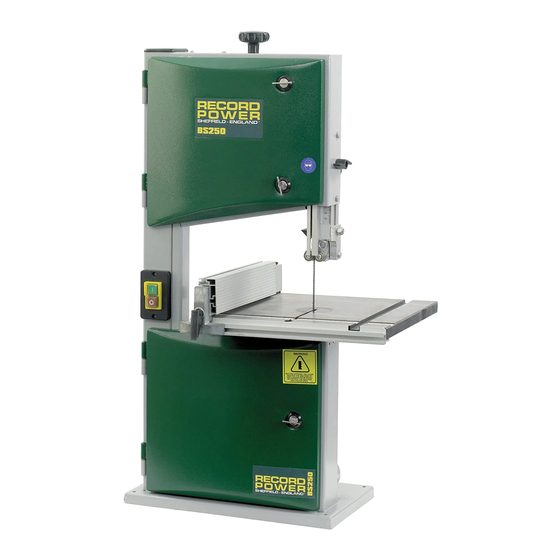
Page 8: Getting To Know Your Bandsaw
1. Getting to Know Your Bandsaw Fig.1 Blade Tensioning Knob Tracking Knob Rise & Fall Lock Tracking Knob Lock Blade Motor Rating Plate Upper Blade Guide Table Tilting Handle Mitre Fence 100 mm Dust Extraction Port Rip Fence Motor Rip Fence Rail Table Stand &... -
Page 9: Assembly Of The Optional Stand & Wheel Kit
3. Assembly of the Optional Stand & Wheel Kit 3.1 Stand & Wheel Kit Assembly Fig.3.1 CAUTION! The machine is heavy. Additional help or a suitable lifting device or support will be required for lifting the machine onto the stand. The stand and wheel kit comes as a self assembly unit Fig.3.1. - Page 10 3. Assembly of the Optional Stand & Wheel Kit - cont. Fig.3.2 Fig.3.6 LONG MID BRACE SUPPORTS Note: When assembling this legstand Do Not fully tighten the nuts and bolts until the assembly is complete. Finger tight LONG TOP BRACE should be sufficient.
- Page 11 3. Assembly of the Optional Stand & Wheel Kit - cont. Fig.3.9 Fig.3.14 CAUTION: When assembling the wheel AXLE kit, ensure that the operating pedal is positioned so that it protrudes through the front of the stand (i.e. the area of the stand without the short mid brace support fitted).
- Page 12 3. Assembly of the Optional Stand & Wheel Kit - cont. Fig.3.17 LONG FIXING BOLTS Fig.3.19 Note Before fully tightening all of the fixtures on the stand ensure that the long fixing bolts and nuts are fitted through each top corner of the stand. Once this is complete the rest of the stand can be fully tightened and the bandsaw can be fitted.
-
Page 13: Machine Assembly
4. Machine Assembly 4.1 Unpacking and components included Fig.4.1 The machine is supplied partly assembled. Prior to use, further assembly is required. When unpacking the machine the following components are included for the initial assembly Fig.4.1: 1. 1 x Table 2. - Page 14 4. Machine Assembly - cont. At this stage it is advisable to make an initial Fig.4.1A Fig.4.5 setting in the lower blade guides, slacken the TWO GRUB SCREWS two left hand side grub screws Fig.4.1A, then position the guide assembly so the blade runs centrally on the rear thrust bearing Fig.4.1B.
- Page 15 4. Machine Assembly - cont. 4.4 Fitting table alignment screw Fig.4.9 Pass the socket head screw through the hole in the front edge of the table and fence rail and secure with the M6 plastic winged nut and washer Fig.4.4 B. 4.5 Fence alignment 1 FENCE Adjustment can be made to the fence in relation...
-
Page 16: Machine Setting
5. Machine Setting Fig.5.1 TABLE TILT MECHANISM (TRUNNION) CAUTION! Before carrying out any adjustments or maintenance ensure SCALE POINTER that the machine is isolated and disconnected from the electricity supply. 5.1 Tilting the table The tilt mechanism will be used when squaring the table to the blade. Tilt the table as follows: Loosen the lock handle on the table trunnion. - Page 17 5. Machine Setting - cont. Fig.5.4 Fig.5.5 CAUTION! Before carrying out any adjustments or maintenance ensure that the machine is isolated and disconnected from the electricity supply. 5.4 Tensioning the blade The blade tensioning knob should be used to increase or decrease tension. The only accurate way to check a blade is with a tension meter.
-
Page 18: Bandsaw Blade Set Up
6. Bandsaw Blade Set Up Fig.6.1 LOCK NUT CAUTION! Before carrying out any adjustments or maintenance ensure GUIDE CARRIER that the machine is isolated and disconnected from the electricity supply. 6.1 Adjusting the Upper Guides ROLLER GUIDE First check that all of the roller guides are moving freely. To adjust the upper blade guides, position the guide assembly relative to the blade by SOCKET HEAD SCREW slackening off the lock nut Fig.6.1 and moving the guide carrier until the... - Page 19 7. Electrical Connection & Wiring Diagram Machines supplied for use in the UK are fitted with a 3 pin plug conforming machine. If replacing the original fuse, always fit a fuse of equivalent rating to BS1363, fitted with a fuse conforming to BS1362 and appropriate to the to the original.
-
Page 20: Operation & Bandsawing Practice
Remove the faulty component and replace only with genuine Record Power replacement parts. Any electrical components should only be replaced by a suitably qualified person. To replace a broken blade, please refer to the section of this manual entitled “Band saw Blade Set Up”. - Page 21 8. Operation & Bandsawing Practice - cont. Blade Selection (TPI) - Cont. Material Material Thickness Having selected an appropriate blade for the particular thickness and type <6 mm 6-12 mm 12-25 mm >25mm of material to be sawn, it is essential that the saw blade is allowed to cut Perspex 16 TPI 14 TPI...
- Page 22 3/8 x 6 TPI Bandsaw Blade 5/8 x 6 TPI Bandsaw Blade Note: As well as the blades listed, we can also supply bandsaw blades to almost any specification please call Record Power Customer Services in your country. Narrow Blade...
- Page 23 8. Operation & Bandsawing Practice - cont. Ex. 2. Always support round pieces with a wedge or vee block. Take extreme Ex. 5. Jig for accurate repetitive wedges. care as there is a danger that if the work is not secured properly the blade will snatch the work piece, potentially causing it to spin or bounce back at you.
-
Page 24: Dust Extraction
Record Power Extractors be switched off for 20 minutes every hour. 0.5 micron filtration Record Power offer a range of high quality dust extractors, we offer both drum and bag type extractors which filter down 0.5 micron providing CX2000 Compact Chip Extractor protection from harmful fine dusts. -
Page 25: Maintenance
10. Maintenance Fig.10.1 CAUTION! Before carrying out any adjustments or maintenance ensure that the machine is isolated and disconnected from the electricity supply. 10.1 Replacing the bandsaw blade RIP FENCE & RAIL HAZARD! Take great care when unpacking the bandsaw blade as they are usually folded and REMOVED can spring out very suddenly with great force. - Page 26 10. Maintenance - cont. Fig.10.4 Fig.10.9 CAUTION! Before carrying out any adjustments or maintenance ensure that the machine is isolated and disconnected from the electricity supply. 10.2 Replacing the drive belt Note: Circlip pliers are required for this procedure To replace the drive belt slacken the tension on the belt by loosening the motor pivot screw on MOTOR PIVOT SCREW the back of the machine, lifting the motor and...
- Page 27 10. Maintenance - cont. 10.4 The table insert Fig.10.9 The table insert on a bandsaw is a consumable item Fig.10.9 and will therefore need replacing periodically. This procedure should be carried out with the bandsaw blade removed. To replace the table insert simply push the old insert out from underneath the table and fit the new one into position.
-
Page 28: Parts Diagram
11. Parts Diagrams Optional Stand & Wheel Kit Ref No. Description Pedal Hex screw M6 x 35 Nut M6 Long top brace support Washer 10 mm Axle Fixing pins Short stem wheels Pan Head screw M4 x 30 Long stem wheels Release pedal Legs Self nut M4... - Page 29 11. Parts Diagrams - cont.
-
Page 30: Parts List
12. Parts List Ref No. Description Ref No. Description Bandsaw Frame J-belt Upper Door Lower bearing bolt Lower Door Motor Upper Wheel Motor pulley Ball Bearing - 80100 Lower table trunnion Wing nut Wheel pulley Pan head self tapping screw – ST4.8 x 22 mm Lower guide mount Star lock cap Pin guide seat... - Page 31 EU Declaration of Conformity Cert No: EU / BS250 / 1 RECORD POWER LIMITED, Centenary House, 11 Midland Way, Barlborough Links, Chesterfield, Derbyshire S43 4XA declares that the machinery described:- Type: Bandsaw Model No: BS250 Serial No ................. Conforms with the following directives:-...
- Page 32 Woodworking Machinery & Accessories United Kingdom Eire Australia New Zealand France Record Power Ltd Record Power Ltd Tools 4 Industry Tools 4 Industry Robland France Polybois Centenary House, Centenary House, Po Box 3844 Po Box 276079 3 Avenue des Violettes...
Need help?
Do you have a question about the BS250 and is the answer not in the manual?
Questions and answers