
Related Manuals for EMS Sky Connect Series


Summary of Contents for EMS Sky Connect Series
-
Page 1: Installation Manual
1616-964-12 Date: 7/27/2011 Rev. 2.1 EMS Aviation, Inc. Sky Connect Aviation Series Installation Manual TRACKER Part Number 1616-964-12... - Page 2 1616-964-12 Date: 7/27/2011 Rev. 2.1 Aviation Certification Issues CERTIFICATION – Sky Connect has rights to several Supplemental Type Certificates. Use of this information is provided with purchase of the equipment. Assistance in certification efforts to the installers is offered at no charge to the customer or installer. Assistance is provided on Sky Connect’s scheduling.
-
Page 3: Table Of Contents
1616-964-12 Date: 7/27/2011 Rev. 2.1 TABLE of CONTENTS LIST OF REVISIONS..............v INDEX OF ACRONYMS. - Page 4 1616-964-12 Date: 7/27/2011 Rev. 2.1 APPENDIX A Troubleshooting............5 - 1 INSTALLATION AND SYSTEMS DRAWINGS..
- Page 5 1616-964-12 Date: 7/27/2011 Rev. 2.1 LIST OF REVISIONS Revision # Description of Change Date Approval Removed all POTS unit information and 3/24/2007 created a new manual part number for Tracker only. Added Combo antenna, corrected note on 3/20/2008 ICSM, revised pin out chart to remove the 400 series references.
- Page 6 1616-964-12 Date: 7/27/2011 Rev. 2.1 INDEX OF ACRONYMS Field Of Interest (a position) Geographic Information System Icarus Dial Tone IMEI International Mobile Equipment Identifier L Band Transceiver Private Branch eXchange POTS Plain Old Telephone System Personal Unblocking Code Short Burst Data Subscriber Identity Module Short Message Service For a complete definition of terms see http://www.telestial.com/glossary.htm on the Web.
-
Page 7: General Information
Sky Connect Systems. Operating procedures are also included. SYSTEM DESCRIPTION The Sky Connect series satellite communications device consists of a transceiver, an L-band antenna, and a dialing/audio/data interface device. The remote mounted transceiver is the heart of the system, and contains the Iridium satellite LBT (L-Band Transceiver). - Page 8 1616-964-12 Date: 7/27/2011 Rev. 2.1 Figure 1 Tracker & Communication Concept Drawing 1 - 2...
-
Page 9: Technical Specifications
1616-964-12 Date: 7/27/2011 Rev. 2.1 TECHNICAL SPECIFICATIONS 1.3.1 TRANSCEIVERS Part Numbers 1616-XX0-0X all Transceivers are the same with the exceptions listed in the below table. ITEM SPEC Regulatory Compliance: DO-160D, FAA STC on Part 25, 27, and 29 aircraft. FAA-PMA Temperature Range: Section 4 Cat D2 (-20C to +55C) Altitude Range:... - Page 10 1616-964-12 Date: 7/27/2011 Rev. 2.1 ITEM SPEC Connectors: TNC female (Iridium), BNC female G.P.S., 62 pin High Density D-sub connector 1.3.5.2 SOP DIAL PAD SIX POSITION 1616-051-01/03 SOP 6 Dialer has been discontinued. 1.3.5.3 SOP DIALER ELEVEN POSITION 1616-052-00/02 ITEM SPEC Weight 8 oz.
- Page 11 1616-964-12 Date: 7/27/2011 Rev. 2.1 1.3.5.4 MISSION MANAGEMENT UNIT 1616-055-00/10/11/12/13 ITEM SPEC Regulatory Compliance: FAA STC on Part 27, and 29 aircraft. (MMU II only part 29) FAA- Weight: 15 oz. Physical Dimensions: (Depth) 3.375 Inches(MMU) 5.65 (MMU II) (Width) 5.75 Inches (Height) 1.875 Inches...
- Page 12 1616-964-12 Date: 7/27/2011 Rev. 2.1 1.3.5.6 CONFIGURATION MODULE 1616-905-01 This part has been discontinued, see earlier manuals. 1.3.5.7 CONFIGURATION/SIM MODULE 1616-905-02 ITEM SPEC Regulatory Compliance: FAA STC on Part 27, and 29 aircraft. FAA-PMA Weight: 16 oz. Physical Dimensions: (Length) 2.5 inches (without mating connectors) (Width) 2.125 inches...
- Page 13 1616-964-12 Date: 7/27/2011 Rev. 2.1 1.3.6 ANTENNAS 1.3.6.1 IRIDIUM LOW PROFILE ANTENNA 1616-880-01 AeroAntenna AT2775 -XXX ITEM SPEC Regulatory Compliance: TSO C-144, DO-160D Operating Temp: -55 Deg to +85 Deg C Weight: .5 Lbs Max. Physical Dimensions: 3.5 inches in diameter Frequency: 1595 +/- 30 Mhz Connectors:...
- Page 14 1616-964-12 Date: 7/27/2011 Rev. 2.1 1.3.6.3 SENSOR G.P.S. ANTENNA 1616-880-04 ITEM SPEC Regulatory Compliance: TSO C-144, DO-160D Operating Temp: -67 Deg F to +185 Deg F Weight 5 Oz. Physical Dimensions: 3.5 inches in diameter X .57 Inches High Frequency: 1575.42 MHz Connectors: TNCF...
-
Page 15: Installation Process
1616-964-12 Date: 7/27/2011 Rev. 2.1 INSTALLATION PROCESS INSTALLATION PROCESS OUTLINE Note: Make a plan to cover the follow items in depth in this manual. WIRING DIAGRAM 2.1.1 G.P.S. interface, or use of an internal G.P.S. 2.1.2 Event switches, optional 2.1.3 Diagnostic port, must be installed for configuration 2.1.4 Configuration/SIM module, optional 2.1.5 Selection of Dialers optional SIM CARD ACTIVATION... -
Page 16: Tracker Mapping System
1616-964-12 Date: 7/27/2011 Rev. 2.1 TRACKER MAPPING SYSTEM Decide what mapping system is to be used for tracking the aircraft. Setup an account with that provider and secure ID and passwords. Make sure this installation is added to the account that handles the mapping. It is the responsibility of the owner to add aircraft to the mapping system, Sky Connect can NOT do that for you unless it is the Sky Connect Webmap you are using. - Page 17 1616-964-12 Date: 7/27/2011 Rev. 2.1 through the proper setting of the squat switch, and or software settings from the tracker setup configuration software. 2.9.1.10 Our server must be set to pass the data on to the proper map program. 2.9.1.11 Our server must have been set up for the customer (activation form completed and sent in to our office).
- Page 18 The predetermined functions of the switches on the 11 position dialer are: 2.10.2.1 Emergency - typically to declare and aircraft emergency. 2.10.2.2 Code - used mostly by EMS operators to declare a patient emergency. 2.10.2.3 Position - mark a position of interest to the pilot or crew. 2.10.2.4 Dialer - 4 event switches are used to dial the programmed numbers.
- Page 19 1616-964-12 Date: 7/27/2011 Rev. 2.1 2.10.4 Server Software Options Sky Connect Server Software is capable of the following settings. 2.10.4.1 Sending an email when the unit has missed a report. This is determined in the software by looking at the report rate interval and making the determination that an interval has passed without a report from the transceiver.
- Page 20 1616-964-12 Date: 7/27/2011 Rev. 2.1 This page intentionally left blank 2 - 6...
-
Page 21: Installation - General
1616-964-12 Date: 7/27/2011 Rev. 2.1 INSTALLATION - GENERAL PRIOR TO INSTALLATION Perform a visual inspection of the equipment for evidence of damage incurred during shipment. A DISCUSSION ON SIM CARDS It is Sky Connect policy to ship all units with a deactivated SIM card. The unit is tested with a DEMO card before leaving our facility. -
Page 22: Items Required But Not Supplied
1616-964-12 Date: 7/27/2011 Rev. 2.1 ITEMS REQUIRED BUT NOT SUPPLIED; Table 1 ITEMS Daniels Manufacturing Crimper P/N M22520/2-01 Daniels Manufacturing Crimper Positioner P/N K41 Daniels Manufacturing Crimper Positioner P/N K1S All M24308 connectors Crimping tools for use on coax connectors All coax connectors Coax connectors for antenna cable if locally made Contact insertion/removal tool... - Page 23 1616-964-12 Date: 7/27/2011 Rev. 2.1 ITEMS Vivisun# 95-42-12-K6-70881 (2LA DIAL; 3J0 ////) Dial Switch Vivisun# 95-40-18-K6-70957 (2JA CALL; 3JA TEXT) Call/Text - Annunciator Suggestions for coax connectors and tools (customer supplied); Table 2 Connector Coax Tool Newark# Industrial# BNC male RG400/RG142 CTL-1 89F2891...
-
Page 24: General System Components That Apply To All Systems
GENERAL SYSTEM COMPONENTS THAT APPLY TO ALL SYSTEMS Table 3 Product Part Number Description 1616-700-01 Inmarsat Filter 1616-900-99 Sky Connect Series CD ROM 1616-950-XX Aviation Installation Manual, current revision 1616-901-XX Quick Start User Manual, current revision 1616-050-80 SBD Message Traffic 1616-104-01... - Page 25 1616-964-12 Date: 7/27/2011 Rev. 2.1 Description And Components Product Part Number 1616-105-01 Transceiver tray 1616-150-01U Upgrade kit for adding Tracker with G.P.S. to POTS system 1616-150-02U Upgrade kit for adding Tracker without G.P.S. to POTS system S67-1575-39 G.P.S. Antenna 1616-050-01/03/05 only 1616-500-01 SatTalk II Interface 1616-055-XX...
-
Page 26: General Installation Instructions
1616-964-12 Date: 7/27/2011 Rev. 2.1 GENERAL INSTALLATION INSTRUCTIONS 3.6.1 ANTENNA PLACEMENT The Aero-Antenna AT2775 L-Band antenna should be placed as far as practical from other transmitting antenna. A minimum of 30 inches is recommended to other L-Band transmitting antenna. The Iridium antenna is itself a transmitting antenna, and as such, an eighteen inch minimum spacing to G.P.S. - Page 27 1616-964-12 Date: 7/27/2011 Rev. 2.1 3.6.2 ANTENNA CABLE When routing antenna cable, avoid high current wiring, other transmitting antenna cables, and sharp bends. Antenna cable should be selected to obtain 3dB max loss at 1.6GHz. The installer is responsible for providing antenna cables. Use the following chart as an aid to determine the appropriate cable type for your required installed length.
- Page 28 1616-964-12 Date: 7/27/2011 Rev. 2.1 3.6.3 TRANSCEIVER STRUCTURAL MOUNTING The Sky Connect Transceiver should be mounted in accordance with standard practices found in FAA Advisory Circular 43.13-2A. The Transceiver is approved for mounting outside the pressure vessel. See Figures 2 and 3 for unit and tray dimensions.
- Page 29 1616-964-12 Date: 7/27/2011 Rev. 2.1 3.6.4 TRANSCEIVER ELECTRICAL INSTALLATION Wiring must be done in accordance with FAA AC43.13-1B, or most current revision. A crimp tool meeting Mil Spec M22520/2-01 and a positioner are required to ensure consistent, reliable crimp contact connections for the 62-pin D Subminiature connector.
- Page 30 1616-964-12 Date: 7/27/2011 Rev. 2.1 3.6.5 TRANSCEIVER PIN ASSIGNMENTS The below Table is a listing of pin assignments and signal flows. This table applies only to 1616-050-0XA transceivers. For non A models refer to older install manuals. Table 6 Description Flow Ground Input Ground Input...
- Page 31 1616-964-12 Date: 7/27/2011 Rev. 2.1 Description Flow Data out Hi – Diagnostics output RS232 #2 Hi – Messenger output Data in Hi – Diagnostics input RS232 #2 Hi – Messenger input PC S RX (Data Connections only) RS232 #1 Hi – Serial G.P.S. input Program-md1-- Factory Use Do Not Connect Program-RST-- Factory Use Do Not...
- Page 32 1616-964-12 Date: 7/27/2011 Rev. 2.1 3.6.6 MMU II PIN ASSIGNMENTS The table below indicates the pin out of the MMU II J1 - Data J2 - DO NOT CONNECT 28 VDC Polarized Key RS 485 HI RS 485 LO RS 485 HI RS 485 LO Unit ID #1 Unit ID #2...
-
Page 33: Tracker System
1616-964-12 Date: 7/27/2011 Rev. 2.1 TRACKER SYSTEM INSTALLATION NOTE: All added features to the Tracker, such as Altitude Trigger, and Change of Flight Plan feature can increase the cost of operation of the tracker. Check with your operations department prior to turning on features that may increase the cost of operation. -
Page 34: Configuration/Sim Module
1616-964-12 Date: 7/27/2011 Rev. 2.1 the ICM is connected at startup, the configuration is read from the ICM. If it is not present at startup, the system uses its internal memory which is re-flashed by the ICM at startup when connected. 4.1.3 CONFIGURATION/SIM MODULE The Configuration/SIM Module (ICSM) part number 1616-905-02, has the... -
Page 35: Tracker Sop Dialer
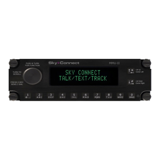
1616-964-12 Date: 7/27/2011 Rev. 2.1 4.1.4 TRACKER SOP DIALER There are two SOP Dialers, a six position and a eleven position. The six position is a very basic design with lighting for the switches but not for the panel. There is no NVIS version of this unit. The eleven position dialer has a back lit face plate and the dimming feature to the panel lights and the annunciators can be separate or together. - Page 36 1616-964-12 Date: 7/27/2011 Rev. 2.1 Figure 10 MMU II Figure 11 4 - 4...
-
Page 37: Tracker-Sop Structural Mounting
1616-964-12 Date: 7/27/2011 Rev. 2.1 TRACKER-SOP STRUCTURAL MOUNTING The Tracker SOP A has eliminated the use of the SatTalk 2 audio controller, and only the RT and the SOP Dialer or MMU need be considered for mounting. If you are using the original version of the SOP system (P/N 1616-050-03/-04), the Sat Talk 2 audio controller normally is installed using a flange mounting plate that is supplied and may be attached to the bottom of the audio controller using the existing screws that secure the bottom plate. - Page 38 1616-964-12 Date: 7/27/2011 Rev. 2.1 The SOP dialer should be powered through either a bright/dim switch, or through a rheostat. If not connecting the dialer to a dimmer buss, connect to 14/28 VDC through a circuit breaker. The dialer is entirely passive and can be dimmed through a range of 4-11VDC.
- Page 39 1616-964-12 Date: 7/27/2011 Rev. 2.1 When using an external GPS receiver, in order for the Tracker to include aircraft altitude in the data that is sent to the ground, a Garmin GPS receiver (430/530/480, etc) must be used in order to get altitude data from the navigation RS-232 data stream.
-
Page 40: Post Installation Testing
1616-964-12 Date: 7/27/2011 Rev. 2.1 MMU/MMU II Annunciators - The MMUs have their own annunciator that will illuminate a light for the following reasons; Incoming Message - To provide a heads up indication to the pilot if the MMU is installed out of the scan view of the pilot, the “Incoming MSG” light will blink slowly for five seconds. - Page 41 1616-964-12 Date: 7/27/2011 Rev. 2.1 4.4.1.3 WiFi Transmit Power - Select the power level for the MMU to operate WiFi. For aircraft use, this should typically be 6. (only appears for MMUs with WiFi capability) 4.4.1.4 Brightness Control - Select one of the following: 1.) Manual –...
- Page 42 1616-964-12 Date: 7/27/2011 Rev. 2.1 4.4.1.8 DTMF Total Time - This is the time for a tone from the start of one digit to the start of the next. The default value of 1016 works for most applications. To determine the duration in seconds, multiply the value by 246 uSecs. For example, the default value of 1016, times 246 uSecs, is 0.25 seconds.
- Page 43 1616-964-12 Date: 7/27/2011 Rev. 2.1 4.4.1.15 Volume Tap - Select from the following options: 1.) Not Enabled – neither offhook nor flash are enabled 2.) Offhook – allow taking phone offhook from ringer volume page 3.) Flash – allow flashing of the line (go onhook for 90 ms) from phone volume page 4.) Offhook &...
- Page 44 1616-964-12 Date: 7/27/2011 Rev. 2.1 4.4.2 MMU II Master vs. Slave Configuration This configuration will allow two MMU IIs to be used connected to one transceiver. The function here, since the RS485 has not yet been implemented, would be to allow two MMU IIs to connect and carry on a phone conversation as in a party line situation.
- Page 45 1616-964-12 Date: 7/27/2011 Rev. 2.1 4.4.2.1 Master Unit Configuration Step Procedure Apply Power to the Master MMU II When the Screen displays the MMU Version and MSet hold the * button (Upper Right) and press the KNOB in while making a turn one click counter-clockwise, then release both the knob and the * button.
- Page 46 1616-964-12 Date: 7/27/2011 Rev. 2.1 4.4.2.2 MMU II Slave Configuration Step Procedure Apply Power to the Slave MMU II Controller. When the Screen displays the MMU Version and MSet version, press and hold the * button (Upper Right) and press the main KNOB in and turn one click counter-clockwise, then release both the knob and the * button.
- Page 47 Master/Slave Testing Step Procedure Apply Power to the EMS Sky Connect Transceiver and the both the Master and Slave MMU II Controllers. Operation of the Master MMU II should be as normal. Place an incoming call to the aircraft. The external Call Annunciator should flash (if installed).
- Page 48 1616-964-12 Date: 7/27/2011 Rev. 2.1 Loading of Message Sets Loading the Message Sets into the MMU II may be done in one of two ways. A.) Serial port of a PC connected to the pigtail of the MMU II harness via a 9 pin serial port cable.
-
Page 49: Tracker Setup
1616-964-12 Date: 7/27/2011 Rev. 2.1 TRACKER SETUP See the software manual to configure the unit to work as the customer desires. NOTE: This is a very important step in installing the system correctly, DO NOT SKIP CONFIGURING THE TRACKER. Tracker Setup using the MMU II as a setup device. If you are installing a MMU II in the system, the MMU II maybe used as a terminal to allow Tracker Setup without a PC connected to the transceiver. - Page 50 1616-964-12 Date: 7/27/2011 Rev. 2.1 internal G.P.S., allow the unit to run for up to 15 minutes on the initial startup to allow the internal G.P.S. to acquire almanac data. Allow one minute for the system to register on the iridium network. Within this registration time, Tracker will generate a start up message which will be sent via the Iridium network to our switching network, and then to the mapping system.
-
Page 51: Operation
1616-964-12 Date: 7/27/2011 Rev. 2.1 position report updates at its programmed interval. Once registered on the network, Tracker interval reports are billed per hour of use including during the testing process. Note: Programmed interval directly affects customer billing. Consult with end user regarding all available configuration options before accomplishing. - Page 52 1616-964-12 Date: 7/27/2011 Rev. 2.1 Examples of Event Switch usage would be; Engine Oil Pressure Low Rotor RPM Engine Out Engine Fire Engine Chip Gear Box Chip Any of the above that will trigger a switch closeure, a ground to turn on a lamp, can be used to trigger an event report from the Tracker.
- Page 53 1616-964-12 Date: 7/27/2011 Rev. 2.1 4.8.2 TRACKER SOP A Tracker SOP A is a new version of the original Tracker SOP but without the need for the SatTalk II audio controller component. The audio operations of the SatTalk 2 are now included in the Tracker SOP “A” transceiver. This brings the operational characteristics of the Tracker SOP “A”...
- Page 54 1616-964-12 Date: 7/27/2011 Rev. 2.1 4.8.3.2 SOP 11 (ELEVEN POSITION DIALER) See this section for a visual of the 11 position dialer. 11 programmable positions. The rotary knob serves as the dial button by pushing in on the knob. To hang up, push a second time. The dimmer feature of the unit works on a true 6 to 28VDC range.
- Page 55 1616-964-12 Date: 7/27/2011 Rev. 2.1 The MMU/II communicates with the map application via binary SBD messages. Mobile Terminated (“MT”) messages are sent from the ground to the MMU, and Mobile Originated (“MO”) messages are sent from the MMU to the ground. These messages are sent to and from the Map. Phone numbers and messages are created for the MMU/II by using a Sky Connect program called MSETgen (MMU) or Mset Manager (MMU II).
- Page 56 1616-964-12 Date: 7/27/2011 Rev. 2.1 4.8.5 MMU/MMU II INDICATIONS First the aircraft must be outside and have a clear 360 degree view of the sky. Normal Start up procedure for the MMU after power on is to indicate a “MMU Starting”...
-
Page 57: Appendix A Troubleshooting
1616-964-12 Date: 7/27/2011 Rev. 2.1 APPENDIX A Troubleshooting TROUBLESHOOTING THE SKY CONNECT SYSTEMS Table 12 Description of Problem Possible Causes TRACKER SYSTEMS Tracker System light flashes software Verify that you are not currently connected rev, shortly thereafter the light goes to the Tracker Setup Program, or the solid and remains solid. - Page 58 1616-964-12 Date: 7/27/2011 Rev. 2.1 Description of Problem Possible Causes Tracker system light pulses, and goes solid, No communication is being made with the but winks off every five seconds. It Iridium Network. continues to pulse, then goes solid followed by the wink off without any pause Verify Signal Strength using Tracker Setup (constantly trying to transmit).
- Page 59 1616-964-12 Date: 7/27/2011 Rev. 2.1 Description of Problem Possible Causes MMU display never reaches the “READY” The initial power on test of the MMU and page hand shaking with the transceiver should follow the below sequence. The MMU should indicate software version and MSet version MMU will display a “MMU Starting”message.
- Page 60 1616-964-12 Date: 7/27/2011 Rev. 2.1 INSTRUCTIONS FOR CONTINUED AIRWORTHINESS Samples of the FAA approved ICAs can be found at the Sky Connect website www.skyconnect.aero under the support tab, and the manuals and guides link. ICAs are provided for the various STCs Sky Connect holds on its products. These ICAs may be used as reference material to develop your own ICA for an installation not covered by one of the STCs.
-
Page 61: Installation And Systems Drawings
1616-964-12 Date: 7/27/2011 Rev. 2.1 INSTALLATION AND SYSTEMS DRAWINGS The following attached drawings are presented as a suggestion on how the system could be installed. If you have any question on installation methods or techniques, please call Technical Services. Electrical Interface of Components Tray - 1616-105-01 Antennas 1616-880-00 Iridium... - Page 62 EMS Aviation is expressly forbidden. Any misuse of this ITEM PART NUMBER DESCRIPTION SUPPLIER document including (but not limited to) quotation in part without written consent of EMS Aviation is expressly forbidden. PARTS LIST Drawn All dimensions are in inches unless Michael Freyder 01/31/2005 otherwise specified.
- Page 63 EMS Aviation is expressly forbidden. Any misuse of this document including (but not limited to) quotation in part without written consent of EMS Aviation is expressly forbidden. Drawn All dimensions are in inches unless...
- Page 64 EMS Aviation is expressly forbidden. Any misuse of this document including (but not limited to) quotation in part without written consent of EMS Aviation is expressly forbidden. Drawn All dimensions are in inches unless...
- Page 65 EMS Aviation is expressly forbidden. Any misuse of this document including (but not limited to) quotation in part without written consent of EMS Aviation is expressly forbidden. Drawn All dimensions are in inches unless...
- Page 66 REVISION HISTORY PARTS LIST DESCRIPTION DATE APPRO ITEM PART NUMBER DESCRIPTION MATERIAL VENDOR STOCK NUMBER Initial Release 04/12/2007 1616-105-0101 Body, Transceiver Tray Aluminum-5052 Marelco Sheet Metal IC020503-1 Added component information 06/28/2007 1616-105-0102 Foot, Transceiver Tray Aluminum-5052 Marelco Sheet Metal IC020503-2 Moved component information onto individual drawings.
- Page 67 REVISION HISTORY DESCRIPTION DATE APPROVED Initial Release 6/13/2006 Added PMA label, additional specifications, and Note 1. 9/23/2010 Changed PMA label to Sky Connect P/N FAA-PMA 10029 12/13/2010 label (1616-820-13) SPECIFICATIONS: FREQUENCY: 1595 30 MHz (-1.5 dB BAND WIDTH) POLARIZATION: RIGHT HAND CIRCULAR 1.900 AXIAL RATIO: 3.0dB MAX RADIATION COVERAGE:...
- Page 70 REVISION HISTORY DESCRIPTION DATE APPROVED 5.026 Initial Release 4/5/2010 2.200 .800 2.119 .201 THRU .385 X 100° FOR 10-32 MOUNTING SCREWS R6.0 .721 .406 .572 O-RING .784 .937 GENERAL SPECIFICATIONS: WEIGHT: 7.84oz MATERIAL: 6061-T6 ALUMINUM ALTITUDE: 70,000' .143 OPERATING TEMP: -67°F TO 185°F IRIDIUM SPECIFICATIONS: FREQUENCY:...
Need help?
Do you have a question about the Sky Connect Series and is the answer not in the manual?
Questions and answers