golmar Jazz GB2 User Manual
Video door entry system kit
2-wire
Hide thumbs
Also See for Jazz GB2:
- User manual (25 pages) ,
- Quick manual (11 pages) ,
- Quick manual (13 pages)

Related Manuals for golmar Jazz GB2


Summary of Contents for golmar Jazz GB2
- Page 1 TECHNOLOGY Jazz GB2 Video Door Entry System Kit 2-wire installation Code 50122156 REV.0 1 JAZZ VESTA2-VESTA7...
-
Page 2: Table Of Contents
JAZZ GB2 VIDEO DOOR ENTRY SYSTEM KIT - HOUSE INTRODUCTION First of all, we thank and congratulate you for purchasing this product. Our commitment to achieving the satisfaction of customers like you is manifested through our ISO-9001 certification and the manufacture of products like the one you have just purchased. -
Page 3: Safety Precautions
JAZZ GB2 VIDEO DOOR ENTRY SYSTEM KIT - HOUSE SAFETY PRECAUTIONS Always disconnect the power supply before installing or making modifications to the devices. The fitting and handling of these devices must be carried out by authorised personnel The wiring must run at least 40 cm away from any other wiring. -
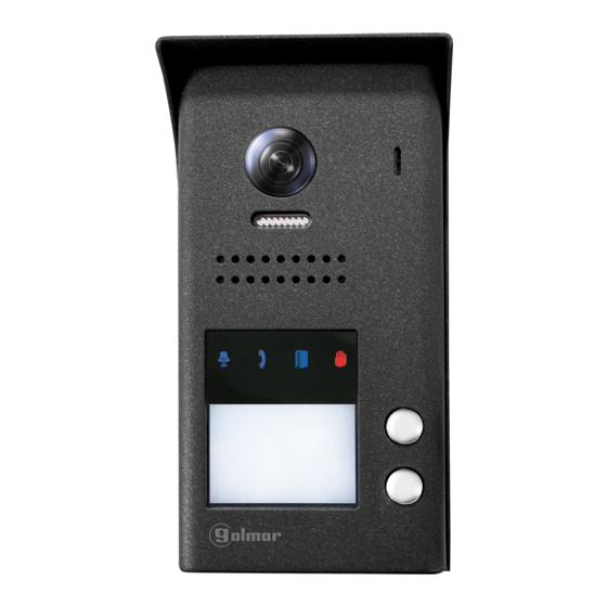
Page 4: Description Of Jazz Surface Panel
JAZZ GB2 VIDEO DOOR ENTRY SYSTEM KIT - HOUSE DESCRIPTION OF THE JAZZ SURFACE PANEL Description of the JAZZ surface panel: AP- C1 NA1 BUSBUS Shield. Call button apartment 1. Colour television camera. Metal front fixing screw (x1). Microphone. Holes for fixing to wall (x4). -
Page 5: Location Of The Door Panel
JAZZ GB2 VIDEO DOOR ENTRY SYSTEM KIT - HOUSE DESCRIPTION OF THE JAZZ SURFACE PANEL Description of the door panel: Exploded view of the parts of the panel. Shield Electronic module Aluminium front JAZZ J5110/VESTA2 1P KIT (Code 11500241). JAZZ J5110/VESTA7 1P KIT (Code 11500242). -
Page 6: Removing The Metal Front
JAZZ GB2 VIDEO DOOR ENTRY SYSTEM KIT - HOUSE INSTALLATION OF THE DOOR PANEL Removing the metal front: Remove the screw at the bottom of the door panel using the Allen key supplied with the product. Remove the metal front as shown in the drawing. -
Page 7: Codes Assigned To The Door Panel Call Buttons
JAZZ GB2 VIDEO DOOR ENTRY SYSTEM KIT - HOUSE INSTALLATION OF THE DOOR PANEL Codes assigned to the door panel call buttons: Button 'P2': Codes 16-21. AP- C1 NA1 BUSBUS (Apartment 2) 2-button door panels only. Button 'P1': Codes 0-5. -
Page 8: Description Of The Configuration Jumper
JAZZ GB2 VIDEO DOOR ENTRY SYSTEM KIT - HOUSE INSTALLATION OF THE DOOR PANEL Description of the configuration jumper: Important: Do not change the configuration jumper's factory position. Factory setting. Description of the door panel illumination LEDs (for low light conditions): The door panel lighting LEDs will turn on during a call if the door panel lighting at that moment is low. -
Page 9: Setting Ringtone Operating Mode
JAZZ GB2 VIDEO DOOR ENTRY SYSTEM KIT - HOUSE INSTALLATION OF THE DOOR PANEL Setting ringtone operating mode: To configure the door panel ringtone when making a call, follow these steps: See p. 7. In the configuration DIP switch, set DIP 1 and DIP 2 to OFF and DIP 3 to ON. -
Page 10: Setting The Activation Time For Cv-/Cv+ (Lock Release) And C1/Na1 (Auxiliary Device)
JAZZ GB2 VIDEO DOOR ENTRY SYSTEM KIT - HOUSE INSTALLATION OF THE DOOR PANEL Setting the activation time for CV- and CV+ (lock release) and C1 and NA1 (auxiliary device): To change the activation time for the lock release and auxiliary device, follow these steps: See p. 7. -
Page 11: Setting The Door Panel Address
Open the label cover (figure A ), insert the label (figure B ) and close (figure C ). Open the label cover * ( ) * ( ) Customise and download the 'JAZZ LABELLER KIT REV.0117' label from Golmar's documentation website: https://doc.golmar.es/search/manual/50180198... -
Page 12: Closing The Door Panel
JAZZ GB2 VIDEO DOOR ENTRY SYSTEM KIT - HOUSE INSTALLATION OF THE DOOR PANEL Closing the door panel: To finish the mounting of the door panel, replace the metal front. Remember: Insert the silicone protective c over the configuration DIP s witch. -
Page 13: Installing The Power Supply Unit (Fa-Gb2/A) And Lock Release
JAZZ GB2 VIDEO DOOR ENTRY SYSTEM KIT - HOUSE INSTALLATION OF THE POWER SUPPLY UNIT Installing the FA-GB2/A power supply unit: Install the power supply unit in a dry protected location free from the risk of dripping or splashing water. -
Page 14: Wiring Diagrams
Configure the end of line in ( ) 1 the last monitor. Lock release DIP 6 to ON. max. 12 Vcc/270mA. Two-apartment installation with 1 VESTA2 monitor per house and Golmar DC lock release. APARTMENT APARTMENT Mains 100~240Vac VESTA2 VESTA2... - Page 15 JAZZ GB2 VIDEO DOOR ENTRY SYSTEM KIT - HOUSE WIRING DIAGRAMS: One-apartment installation with VESTA2 monitors in parallel (In-Out) and Golmar DC lock release. IMPORTANT: Maximum 4 monitors in parallel (without distributors) per installation. Mains 100~240Vac APARTMENT VESTA2 VESTA2 VESTA2...
- Page 16 JAZZ GB2 VIDEO DOOR ENTRY SYSTEM KIT - HOUSE WIRING DIAGRAMS: One-apartment with 6 VESTA2 monitors, 2 DP-GB2A distributors and Golmar DC lock release. End of line VESTA2 VESTA2 CODE 5 CODE 4 VESTA2 VESTA2 CODE 3 CODE 2 End of line...
- Page 17 JAZZ GB2 VIDEO DOOR ENTRY SYSTEM KIT - HOUSE WIRING DIAGRAMS: One apartment with 6 VESTA2 monitors, 3 D2L-GB2 distributors and Golmar DC lock release. VESTA2 VESTA2 End of line CODE 5 CODE 4 VESTA2 VESTA2 End of line CODE 3...
- Page 18 JAZZ GB2 VIDEO DOOR ENTRY SYSTEM KIT - HOUSE WIRING DIAGRAMS: Two apartments with 6 VESTA2 monitors, 2 DP-GB2A distributors and Golmar DC lock release. APARTMENT APARTMENT VESTA2 VESTA2 CODE 16 CODE 2 End of line End of line VESTA2...
- Page 19 JAZZ GB2 VIDEO DOOR ENTRY SYSTEM KIT - HOUSE WIRING DIAGRAMS: Two apartments with 6 VESTA2 monitors, 4 D2L-GB2 distributors and Golmar DC lock release. APARTMENT APARTMENT End of End of line line VESTA2 VESTA2 CODE 16 CODE 2 End of...
- Page 20 Configure the end of line in ( ) 1 the last monitor. Lock release DIP 6 to ON. max. 12 Vcc/270mA. Two-apartment installation with 1 VESTA7 monitor per house and Golmar DC lock release. APARTMENT APARTMENT Mains 100~240Vac VESTA7 VESTA7...
- Page 21 JAZZ GB2 VIDEO DOOR ENTRY SYSTEM KIT - HOUSE WIRING DIAGRAMS: One-apartment installation with VESTA7 monitors in parallel (In-Out) and Golmar DC lock release. IMPORTANT: Maximum 4 monitors in parallel (without distributors) per installation. Mains NOTE: Up to 4 Vesta7 monitors per installation.
- Page 22 JAZZ GB2 VIDEO DOOR ENTRY SYSTEM KIT - HOUSE WIRING DIAGRAMS: One apartment with 4 VESTA7 monitors, 1 DP-GB2A distributor and Golmar DC lock release. NOTE: Up to 4 Vesta7 monitors per installation. VESTA7 VESTA7 CODE 3 CODE 2 End of line...
- Page 23 JAZZ GB2 VIDEO DOOR ENTRY SYSTEM KIT - HOUSE WIRING DIAGRAMS: One apartment with 4 VESTA7 monitors, 2 D2L-GB2 distributors and Golmar DC lock release. NOTE: Up to 4 Vesta7 monitors per installation. VESTA7 VESTA7 End of line CODE 3...
- Page 24 JAZZ GB2 VIDEO DOOR ENTRY SYSTEM KIT - HOUSE WIRING DIAGRAMS: Two apartments with 4 VESTA7 monitors, 2 DP-GB2A distributors and Golmar DC lock release. NOTE: Up to 4 Vesta7 monitors per installation. APARTMENT APARTMENT End of line End of line...
- Page 25 JAZZ GB2 VIDEO DOOR ENTRY SYSTEM KIT - HOUSE WIRING DIAGRAMS: Two apartments with 4 VESTA7 monitors, 2 D2L-GB2 distributors and Golmar DC lock release. NOTE: Up to 4 Vesta7 monitors per installation. APARTMENT APARTMENT End of End of VESTA7...
- Page 26 JAZZ GB2 VIDEO DOOR ENTRY SYSTEM KIT - HOUSE WIRING DIAGRAMS: Video door entry system with 4 access panels, DP-GB2A distributor for door panels and Golmar DC lock release. House with distributors House without distributors (up to 4 monitors) Mains...
- Page 27 JAZZ GB2 VIDEO DOOR ENTRY SYSTEM KIT - HOUSE WIRING DIAGRAMS: Connection of one Golmar AC lock release. Access panel To the FA-GB2/A power supply TF-104 SAR- 2 1 /24 AP- C1 NA1 BUSBUS 230Vca. * ( ) Lock release max.
- Page 28 C/ Silici, 13 08940- Cornellá de Llobregat SPAIN Golmar se reserva el derecho a cualquier modificación sin previo aviso. Golmar se réserve le droit de toute modification sans préavis. Golmar reserves the right to make any modifications without prior notice.
Need help?
Do you have a question about the Jazz GB2 and is the answer not in the manual?
Questions and answers