Table of Contents
Advertisement
Advertisement
Table of Contents

Related Manuals for ThyssenKrupp Flow2A


Summary of Contents for ThyssenKrupp Flow2A
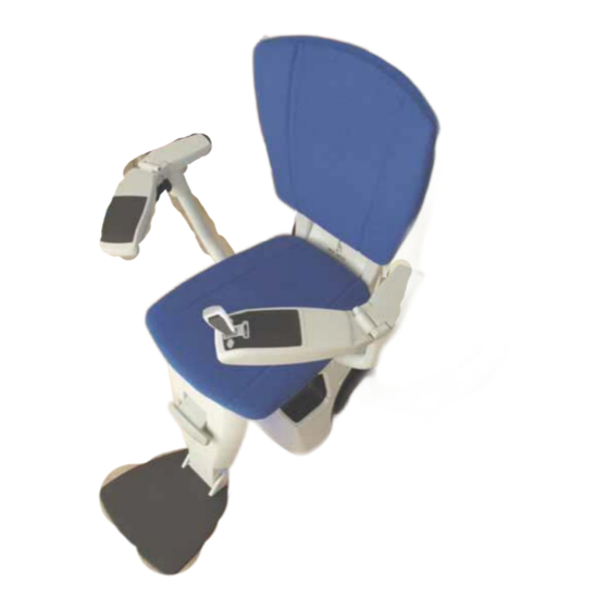
- Page 1 Flow2A chairlift Installation manual...
- Page 2 Subject to the exceptions provided by law, this publication and/or its contents may not be, whether entirely or partly, reproduced, copied, and/or published in print, by photocopying, on microfilm, electronically or in any other way without the prior written consent of ThyssenKrupp Accessibility BV.
-
Page 3: Table Of Contents
Table of contents Preparations ........................4 At the branch ......................4 At the customer’s home ....................4 Installing the rail ......................... 5 Fitting the legs and brackets ..................5 Connecting the rail sections with a section bush ............. 7 Installing the feeder cable .................... 7 Fitting and installing the charging contacts .............. -
Page 4: Preparations
1 Preparations At the branch Check using the installation drawings and the shipping receipt whether all the required parts of the drive unit are present and undamaged, especially: The rail sections and The chair base with the section bushes. control unit. Various loose components, such as: call and park... -
Page 5: Installing The Rail
2 Installing the rail During the preassembly you fit the entire rail together without fixing it to the stairs. 1. Sort the rail sections, brackets and legs by number (refer to the installation drawing). 2. Assemble the rail section for section from the bottom of the stairs to the top: a. - Page 6 The floor bracket: 1. Insert two hammer-head bolts (1) in the openings in the rail flange (2). 2. Fix the floor bracket (3) to the rail flange with the two hammer-head bolts and two Tensilock nuts (4). The tread brackets: 1.
-
Page 7: Connecting The Rail Sections With A Section Bush
2.2 Connecting the rail sections with a section bush 1. Tighten (loosely) the four socket-head screws in the section bush so that the four nuts are trapped in the slot on the inner surface. 2. Fit the section bush in the end of a rail section and adjust it to the correct position. -
Page 8: Fitting And Installing The Charging Contacts
2.4 Fitting and installing the charging contacts 2.4.1 Fixed charging contacts The positions of the fixed charging contacts are prepared on the rail at the factory. The charging contact is installed as follows: 1. Strip approximately 9 cm of the feeder cable. 2. -
Page 9: Movable Charging Contacts
2.4.2 Add-on charging contacts There are also charging contacts that can be fitted afterwards by a technician. The bracket for this charging contact is attached to the rail with two screws. Make sure that when you order this charging contact you also specify the color of the rail. Only mount the movable charging contact at the following places: ... -
Page 10: Connection Of Charging Contacts
2.4.3 Connection of charging contacts CAUTION The connections to the + and - terminals of the bottom charging contacts must be reversed as compared to those of the other charging contacts. This is necessary to enable the drive unit to detect that it has reached the bottom of the stairs and must stop. -
Page 11: Connecting And Mounting The Transformer
2.5 Connecting and mounting the transformer 1. Connect the transformer to the charging contacts closest to a 230Vac wall socket. Use an extension lead if necessary. 2. Put the transformer plug in the wall socket. 3. Check that the voltage is approximately 33 V and the connection is as indicated in the figures above. -
Page 12: Assembly
3 Assembly CAUTION Take ESD precautions, such as a mat, strap and shoes. Never touch a circuit board without taking these precautions. 3.1 Prepare drive unit 1. Place the box with drive unit near the location where it will be driven onto the rail. 2. - Page 13 Before putting in the fuse, please check that all connectors are properly connected to the control board, service board and sensor board. Remove the front (service) cover and put the 30A fuse into the drive (right side next to battery) and switch the drive on by slightly pulling out the red tab on the back.
-
Page 14: Drive Onto The Rail
3.2 Drive onto the rail 1. Position the drive next to the rail, facing front as how it should be when it is on the rail. Now lift up one of the bogie half (The one opposite of the rail) and pull it to the top until it will not go further. -
Page 15: Calibration Of Level Sensors
3.3 Calibration of level sensors Before the lift can be used, the level sensors should be calibrated to ensure a level and steady ride quality. This should be done for the main level sensor (CHr) and safety level sensor (SAF). 1. -
Page 16: Preparing The Drive Unit For Use
Use the installation joystick to drive the unit down the track, use the adapter (1000217) to connect the joystick to the controlboard. (if you have installed it from the top side / when it has a vertical start) until it reaches the charging contact. -
Page 17: Installing The Manual Swivel Seat Fitting
3.7 Installing the manual swivel seat fitting 1. Remove the four threaded ends from the squeeze unit flange without damaging them. Set the threaded ends aside; you will need them later. 2. Remove the two screws. These are no longer needed and can be discarded. -
Page 18: Chair Base Height Adjustment
3.8 Chair base height adjustment The height of the chair base can be adjusted for the customer. This is done by choosing one of the positions. Each position corresponds to a certain height. The following rule of thumb applies for raising the chair base: ... -
Page 19: Height Of The Footrest
3.9 Height of the footrest The position of the footrest depends on the height of the chair base. The following rule of thumb applies for setting the height of the footrest: An increase of one position of the seat height is accompanied by setting the footrest one position lower. -
Page 20: Adjusting The Length Of The Safety Belt
3.10 Adjusting the length of the safety belt 1. Remove the cover on the left armrest with a flat screwdriver. 2. Move the pin to the right hole in the safety belt. 3. Refit the cover. 3.11 Fixing the rail to the stairs After making a test ride, the rail position is optimal. -
Page 21: Registering Controls
3.12 Registering controls A repeater can extend the range of the call/park transmitters. This should be considered if there are 4 floors or more and the floors contain concrete and/or steel. For installing a repeater, please follow the next steps: ... -
Page 22: Setting Mode -8-, Assign Call/Park
3.13 Setting mode -8-, Assign Call & Park The Call & Park functions have to be assigned, this can be done in mode -8-. Figure 3-1: Mode -8- display The RF equipment is now registered and assigned. The C/P units should have a “Chair” symbol at the left button (Call chair to you) and a park “P” letter at the right button (Park chair away). -
Page 23: Safe Point
3.14 Safe position The lift is fitted with a maintenance timer. One of the timers tells the user that the joystick emergency stop should be tested. After 180 hours of (driving) usage, the lift will give a warning to perform the emergency stop test. -
Page 24: Installation Without Raildata Provided
3.15 Installation without raildata provided First the parameters and some settings need to be performed before the rail data is build: Select mode -9-. Press “E” until “CLr” shows in the display. Press and hold “E”, this will clear the rail data and parameters, to be sure these are empty and default. - Page 25 Speed settings: The software will calculate the intermediate speed for each point between two speed settings, also called interpolation. This means that we only program the speed at certain points on the rail, with a minimum of the start (H0) and end point (H1). Figure 3-4: Rail with speed settings Typical speed settings are: ...
- Page 26 Angle settings: As for the speed, the software will calculate the angle at any point by interpolating the two angle points programmed. For the angle changes there are also some rules in place. When the angle changes too quickly, the swivel motor cannot keep up and this can cause warning C87. Figure 3-6: Direction of rotation.
- Page 27 Rotation: A rotation is only possible with an automatic swivel. A rotation can only been programmed at a halt position. The rotation starts when the stair lift is at a halt position. This to ensure that the user rotates away from the stairs and can get out of the chair safely.
- Page 28 3.15.5 Create a backup of the programmed rail data and parameters: Enter mode -9- Press the “E” button repeatedly until “BU” is displayed. Press and hold the “E” button for at least 3 seconds, now “L00” will be shown in display. ...
- Page 29 4 Releasing the chairlift 4.1 On-site installation test The on-site installation test is certified by the Notified Body (Liftinstituut) and complies with the European Harmonized Standard EN 81-40 and the Machinery Directive 2006/42/EC. In order to comply with EN 81-40, you must test the installation on-site. WARNING ...
- Page 30 Rail support (floor bracket) Bolts, 22 Nm Screws, 4.5 Nm Rail support (tread bracket) Bolt and nut, 22 Nm Screws, 4.5 Nm Rail support (tread bracket) Bolt and nut, 22 Nm Rail support (landing bracket) Bolt and nut, 22 Nm Screws, 4.5 Nm...
- Page 31 4.2 Inspecting the installation and the safety devices Check all items on the checklist and tick them off. Drive unit / chair No damage to the paint, the upholstery or the plastic covers. The wiring has been connected correctly and is not pinched. The control buttons operate correctly.
- Page 32 Call-and-park stations The call positions have been correctly set. The park positions have been correctly set. The control buttons operate correctly. All bolts and nuts are tight. Other If the chairlift is not visible from where the call-and-park stations have been installed, convex mirrors have been installed.
- Page 33 Manufacturer ThyssenKrupp Accessibility BV Van Utrechtweg 99, 2921 LN P.O. Box 754, 2920 CB Krimpen aan den IJssel (The Netherlands) Phone: +31 (0)180 530 900 Fax: +31 (0)180 530 901 E-mail: info@tkacc.nl lnternet: www.tkacc.nl...
Need help?
Do you have a question about the Flow2A and is the answer not in the manual?
Questions and answers
The stairlift is out of battery and not at a charging station. How do we manually move it to a charging station? Thank you.