Table of Contents
Advertisement
Quick Links
Advertisement
Chapters
Table of Contents

Summary of Contents for Orlanski ORLIGNO 100 16kW
- Page 1 MANUAL AND SERVICE MANUAL ORLIGNO 100 16, 24,49 kW ISO 14001 ISO 9001...
-
Page 2: Table Of Contents
INSTRUCTION MANUAL Contents 1. Basic informations...................3 1.1. -
Page 3: Basic Informations
1. Basic informations 1.1. Construction description and burner application Burner ORLECO is a new look into the automatic burning of solid fuels in Europe – pellets of 6-8 mm of diameter maintaining low emissions, complying with European norms. Burner doesn’t have any drawbacks of chute burners –gravitational, in which ash and sinter have to be removed manually. -
Page 4: Fuel Characteristics
1.2. Fuel characteristics a) Pellet granulate made according to DIN 51731 - granulate 5-8 mm - recommended calorific value 17500-19500 kJ/kg - ash content 1,5% - max moisture content 12% - density 1-1,4 kg/dm³ ATTENTION! It is recommended to use fuel from reliable sources. Fuel should have appropriate humidity and low content of small fractions. - Page 5 Please check completeness of Orligno 100 pellet package and its condition. ORLIGNO 100 boiler Feeder Burner Refractory bricks burner door Pellet tank...
-
Page 6: Technical Data Of Orligno 100
1.4. Technical data of ORLIGNO 100 Output Boiler class acc to EN 303-5 Efficiency Permissible working pressure Max set temperature °C Recommended return temperature °C Controller setting temperature °C 50 - 80 Water content ltr. Boiler weight Loading chamber capacity ltr. -
Page 7: Boiler Dimensions
1.5. Boiler dimensions... -
Page 8: Boiler Construction
1.6. Boiler construction 1. Pellet tank 8. Water return from heating circuit 2. Controller 9. Firebricks 3. Connection box 10. Heat exchanger 4. Metal connector 11. Flue 5. Burner socket 12. Draft reducer 6. ORLECO burner 13. Hot water outlet 7. -
Page 9: Overheating Valve Connection
1.7. Overheating valve connection ORLIGNO 100 is equipped with copper cooling coil mounted in boiler body, protecting boiler from overheating. To one of cooling coil tappings on right side of the boiler one should connect safety valve. When temperature increases above 95ºC safety valve opens and lets in cold water through cooling coil. - Page 10 16kW 24kW...
- Page 11 49kW 16kW 1. Burner’s body 5. Motoreducer 2. Grate 6. Plate for electric connections 3. Fan 7. Connector 4. Burner's casing 8. Igniter Pic.2. Burner construction...
-
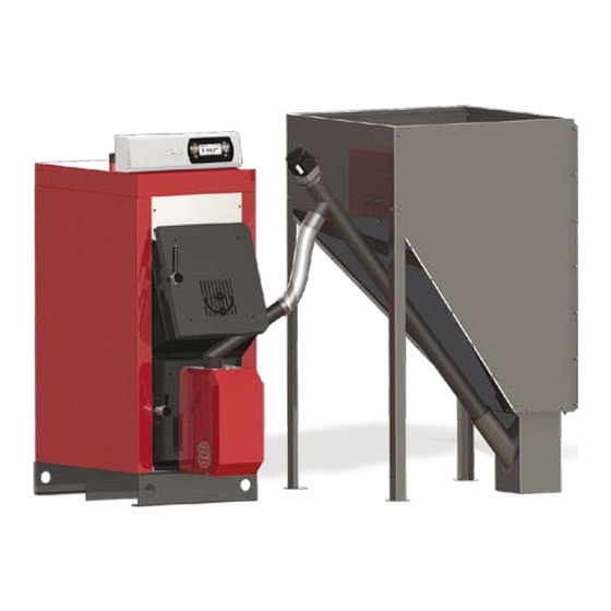
Page 12: Package
ATTENTION! Producer reserves the right for construction and documentation changes in order to modernize the boiler. Boiler Clamp Pellet tank Feeder Elastic pipe Burner Burner’s connector Pic.1. Basic package elements. -
Page 13: Location And Package Installation
4. Location and package installation 4.1. Rules, norms, recommendations Boiler room should comply with construction law valid in country where boiler is installed. min 100 Pic.3. Package layout. -
Page 14: Boiler Room Recommendation
4.2. Boiler room recommendation - Package ( boiler, burner, tank, feeder) should be placed in separate room, centrally to heated rooms - Front door should open outside and must be made of nonflammable materials, with 0,8 width - Floor should be made of nonflammable materials or covered with 0,7 mm steel plate at minimum 0,5 m distance to door edges. - Page 15 Combustibility grade of building Building products products A – non-burning sandstone, concrete, bricks, fire plaster, Mortar, tile, granite B - hard burning cement board, fiberglass, mineral insulation C1- hard burning beech tree, oak tree, plywood C2 – middle burning pine, larch, spruce tree, cork, rubber floor cover C3 –...
-
Page 16: Putting Into Operation
5.1. Burner start First startup of the burner must be done by authorized company trained by manufacturer with valid certificate of authorized serviceman issued by Eko-Vimar Orlanski ltd. 5.2. Burner’s assembly to ORLIGNO 100 1. Remove the screws (1) and side screws (3) fastened to burner’s casing and take off burner's casing (2). - Page 17 Pic.5. Burner assembly. Pic.6. Feeder assembly...
-
Page 18: Tank Assembly
5.4. Tank assembly Bolt M8 A x 34 M5 x 8 Bolt B x 12 M5 x 16 C x 46 M5 D x 18 M8 E x 46 Bolt Washer Washer F x 5 G x 1 H x 1 I x 1 M8 x100 Plug... -
Page 19: Before Starting Of The Burner It Is Necessary
5.5. Before starting of the burner it is necessary: 1. Check installation condition. 2. Fill in pellet to the tank. 3. Check if fuel contains any unwanted elements ( rocks, metal elements). 4. Connect burner's and feeder's plugs. 5. Turn on controller. 6. -
Page 20: Burner's Maintenance
6. Burner’s maintenance ATTENTION! It is necessary to put out, cool down and disconnect burner from power supply when servicing. Pay attention on hot burner’s surfaces – risk of burn. In order to keep high efficiency of burner it is recommended to clean and service it systematically. -
Page 21: Troubleshooting
7. Troubleshooting Type of defect Possible cause of defect Suggested repair One of controller’s Display malfunction Display repair button doesn’t work Automatic lightning Wrong connection of igniter or Check plug and wires connections of igniter and up Doesn’t work photo-cell photo-cell Clogged outlet hole of hot air Clean heater hole... - Page 22 Controller's manual Contents 8. Connection - electric scheme ................24 9.
- Page 23 12.5. Settings ..................42 12.5.1 Date and time.
-
Page 24: Connection - Electric Scheme
8. Connection - electric scheme The device supply voltage is ~ 230V/50Hz. Plug the power cord to the controller in accordance with the posted signs. WARNING! External sensors for installation control such as hot domestic water HW1 or central heating CH1 are an option. They are not included in standard Orligno 100 package. Attach to the controller for operating the boiler sensors and actuators as needed. - Page 25 INPUTS Description Explanation Tboiler Boiler temperature sensor 5 (F-oto) Photocell 6 (Tbur) The temperature sensor burner The temperature sensor hot water Troom Room temperature sensor / regulator (CTP) The temperature sensor central heating Tout Outdoor temperature sensor (CTZ) +12V output to supply optional equipment +5V output to supply optional equipment 7 GND Mass electric to connect sensors...
-
Page 26: Overview Of The Basic Functions
9. Overview of the basic functions 9.1. Control panel 9.1.1 The status LED Status Importance Green light continuously Controller OFF Green blinks Controller enabled, burner OFF Orange light continuously Controller enabled, burner enabled Orange blinks Burner works Red light continuously There is an alarm to be confirmed Red blinks Alarm active... -
Page 27: Buttons
9.1.2 Buttons Function Button Long press on the main screen (>3 seconds) changes the state of the ON/OFF (on/off). ON / OFF Quick access to the full configuration settings for the central heating. Quick access to the full configuration settings for hot water. Shows the navigation information and descriptions of the regulated parameters. -
Page 28: Graphic Display
9.1.3 Graphic display 9.2. Statuses of furnace Status Description TURNED OFF The burner is not working. Permission to work off. CLEANING Cleaning the burner by strong stream of air. FIRING UP Firing up fuel. Providing the initial dose of fuel to run igniter and blower. -
Page 29: Handling
10. Handling 10.1. Navigation in the menu The device has two types of menus: simple and main menus. Simple menu – allows for quick access to basic controller functions. Enter the menu is simple by pressing the “up arrow“ or “down arrow“ on the main screen. Description of a simple menu in chapter 11. -
Page 30: Time Scheduling
10.4. Time scheduling Controller is equipped with a clock and calendar. This makes it possible to program the operation of individual circuit elements for heating depending on the time and day of week. Date and time are not reset during a power failure, because the controller is equipped with a battery that should be replaced every two years. -
Page 31: Service Password
10.5. Service password Access to the service parameters are password protected. After entering the correct password, access will be lifted. Access to the service parameters will be locked after a period of 10 minutes without pushing buttons. Service code is a temperature of the boiler in menu BOILER / SETTINGS and 3 letters”EST”. Example: If the temperature of the boiler in menu BOILER / SETTINGS is 60°C, password is: „60EST”. -
Page 32: Simple Menu
11. Simple menu 11.1. Simple menu screens Screen Description Shows the current temperature of the boiler (large font) and the desired temperature (small font). After pressing the„ENTER” set the desired temperature of the boiler. Shows the current temperature of hot water (large font) and the desired temperature (small font). - Page 33 Shows the current temperature in the room No 1 (large font) and the value of the desired (small font). After pressing the „ENTER” go to set the desired temperature in the room. Menu relates to the circuit No. 1 Set the mode a heating circuit: a.
-
Page 34: Main Menu
12. Main menu... -
Page 35: Heating
12.1 Heating 12.1.1 Selection of circuit Allows you to select a number of central heating circuit. The selection of the circuit make arrows. 12.1.2 State Allows you to monitor the status of central heating system. -
Page 36: Settings
12.1.3 Settings Function Description Comfortable temp. Desired temperature in the room during the heating. Programs: a. time - according to preset intervals b. constant - regardless of the time intervals comfortable temperature is maintained Programme c. disabled - off the heat d. - Page 37 Function Description CH temp. for -20°C The point of the heating curve for -20°C. CH temp. for 0°C The point of the heating curve for 0°C. CH temp. for 10°C The point of the heating curve at 10°C. Service Central heating temperature correction required the desired room temperature for 1 º...
-
Page 38: Hot Water
12.2 Hot water 12.2.1 Selection of circuit Allows you to select the number of hot water circuit. 12.2.2 State Allows you to monitor the status of hot water. -
Page 39: Settings
12.2.3 Settings Function Description Comfortable temp. Desired temperature of hot water during heating. Set the mode a circuit: a. time - according to preset ranges b. constant - regardless of the time intervals comfortable Programme temperature is maintained c. disabled - off the heat. Heat now Heats hot water once to a comfortable temperature regardless of the program. -
Page 40: Buffer
12.3 Buffer (option available only with external module CAN) 12.3.1 State 12.3.2 Settings Function Description Upper set temperature Below this temperature in the upper part of the buffer starts charging. Lower set temperature Above this temperature at the bottom of a buffer comple- tes the process of charging. -
Page 41: Boiler
Function Description Minimal pump temp. The minimum temperature in the upper part of the buffer at which the circulating pump can work for central heating. Specifies whether the upper temperature buffer (minimum) Auto upper temp. is requested manually or automatically. Automatically ba- sed on the needs of other power consumers in the buffer. -
Page 42: Settings
Function Description MIN pump temp. The temperature above which the the controller can attach pumps. Operating mode of boiler: a. auto - temperature calculated automatically Mode b. continuous - the temperature is kept constant Hysteresis The temperature of the boiler must be reduced by this value to launch the burner. - Page 43 12.5.4.1 Module configuration Menu is used to configure the CAN network. In the menu, select the modules that are connected to the system. WARNING! A detailed description of the modules and their destination are described in the manu- al of expansion modules. SUMMARY OF THE EXPANSION MODULES Module Description...
-
Page 44: Burner
12.5.4.2 System configuration Menu is used to configure the heating system (hydraulic). The possibility of settings is dependent of number of expansion modules connected in the system. WARNING! You must first configure the modules.. SYSTEM CONFIGURATION Function Description Number of CH circuits Specifies the number of heating circuits in the system. -
Page 45: Settings
12.6.2. Settings Function Description Feed fuel now Starts fuel feeding screw regardless of other features. Burner on Consent to work of the burner. Fuel type Specifies the type of fuel. 12.6.3. Service WARNING! Access the service is intended only for qualified technical personnel. The changes may cause malfunction of the system. -
Page 46: Alarms
12.7 Alarms This menu contains a history of up to 20 alarms that occurred during the controller work. The importance of alarm codes was presented in table below. 12.7.1. Alarm codes CODE Short description Explanation Processor overheating Procesor overheating. The reason may be improper installation location of the controller. - Page 47 CODE Short description Explanation HW sensor open Room temp. sensor shorted Room temp. sensor shorted Quenching error Lambda communication Solars overheating Solars freezing The codes of the modules Shorted IN1 Module 0 Shorted IN2 Module 0 Shortede IN3 Module 0 Shorted IN4 Module 0 Shorted IN5 Module 0 Shorted IN6 Module0...
- Page 48 CODE Short description Explanation Shorted IN1 Module 1 Shorted IN2 Module1 Shorted IN3 Module 1 Shorted IN4 Module 1 Shorted IN5 Module 1 Shorted IN6 Module 1 Open IN1 Module1 Open IN2 Module 1 Open IN3 Module 1 Open IN4 Module 1 Open IN5 Module 1 Open IN6 Module 1 Overheating Module 1...
- Page 49 CODE Short description Explanation Open IN1 Module 2 Open IN2 Module 2 Open IN3 Module 2 Open IN4 Module 2 Open IN5 Module 2 Open IN6 Module 2 Overheating Module 2 Shorted IN1 Module 3 Shorted IN2 Module 3 Shorted IN3 Module 3 Shorted IN4 Module 3 Shorted IN5 Module 3 Shorted IN6 Module 3...
- Page 50 CODE Short description Explanation Open IN4 Module 3 Open IN5 Module 3 Open IN6 Module 3 Overheating Module 3 Shorted IN1 Module 4 Shorted IN2 Module 4 Shorted IN3 Module 4 Shorted IN4 Module 4 Shorted IN5 Module 4 Shorted IN6 Module 4 Open IN1 Module 4 Open IN2 Module 4 Open IN3 Module 4...
- Page 51 CODE Short description Explanation Overheating Module 4 Shorted IN1 Module 5 Shorted IN2 Module5 Shorted IN3 Module5 Shorted IN4 Module 5 Shorted IN6 Module 5 Shorted IN7 Module 5 Shorted IN8 Module 5 Shorted IN9 Module 5 Overheating Module 5...
-
Page 52: Solar
12.8 Solar (option available only with external module CAN) 12.8.1 State 12.8.2 Settings Function Description Turn on delta Temp. difference between solar and accumulator needed for solar pump turn on. Turn off delta Temp. difference between solar and accumulator needed for solar pump turn off. -
Page 53: Info
12.9 Info There you will find useful information about the controller, including the version of software. 13. Expansion of the system - CAN bus The controller is equipped with a high bandwidth CAN bus used to communicate with the modules. Thanks to the well-known for their reliability, widely used in automotive bus system is expandable to the highest level. - Page 54 Socket CAN bus is on the left side of the device. Connecting cable must be connected according to the following designation. Cable connection: L – line LOW (white) H – line HIGH (brown) GND – ground (grey) For connections on the CAN bus should be only used cable LiYCY 2x0,25. Only this type of cable gives the proper work of devices.
-
Page 56: Sonda Lambda
13.1 Sonda Lambda Lambda sensor we can connect to the system in two ways: – directly to the controller, if the entire system with CAN bus module will only use Lambda oxygen sensor, – through enlargement module I/O with the number 5, if in the system there are other modules enlargement. - Page 57 Find Lambda Module and turn it on by changing the option to YES At this point, turned on the module Lambda. The second step is a change the configuration settings for the burner. From the main menu by selecting BURNER we get to the settings. Here you can again enter the mode SERVICE and if required, enter the access code.
-
Page 58: Solars
13.2 Solars Solar collectors are supported only by enlargement module I/O number 5th. After performing all the connections you must configure the controller to work with collectors proceed as described below. The first step is to enable module number 5. From the main menu select SETTINGS Then in the mode SERVICE enter the access code After inputting the correct code, run the MODULES CONFIGURATION... - Page 59 Now enable the solar handling. As the main menu select SETTINGS and then enter the access code in the SERVICE mode After entering the code run SYSTEM CONFIGURATION Find the position Solars and activate them by changing the settings to YES After finishing configuration the controller we can start to change the adjustment and settings for Solars.
-
Page 60: Specification
14. Specification Technical data Module supply voltage ~230V/50Hz ±10% Power input (module) <6VA Temperature measurement accuracy ±4ºC NTC 10kΩ B25/85=3877K±0,75% Sensors VISHAY BC components Ambient temperature 0-60 °C Moisture 5-95% non-condensing Software class Module output load capacity CH pump 100W HW pump 100W Igniter...
Need help?
Do you have a question about the ORLIGNO 100 16kW and is the answer not in the manual?
Questions and answers