
Related Manuals for Extraflame COMFORT PLUS CRYSTAL


Summary of Contents for Extraflame COMFORT PLUS CRYSTAL
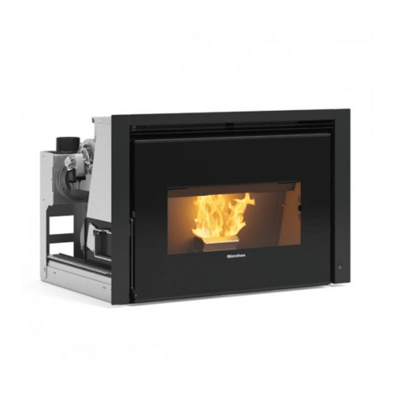
- Page 1 PeLLeT STOveS USeR MANUAL COMFORT PLUS CRYSTAL MADE ITALY design & production 004276732 - Rev 001...
- Page 2 ENGLISH...
-
Page 3: Table Of Contents
WarNINGS ....................................4 SafEty ......................................4 routINE MaINtENaNcE ................................5 INStaLLatIoN .................................... 6 INStaLLING INSErto coMfort PLuS cryStaL ........................8 Assembly with sliding bAse....................................8 inserto ComFort PlUs CrystAl ..................................8 PEdEStaL aSSEMbLy (oPtIoNaL): ............................9 froNt PELLEt fEEdING kIt (oPtIoNaL) ..........................9 aIr cIrcuLatIoN PIPES ................................ -
Page 4: English
We thank you for having chosen our company; our product is a great heating solution developed from the most advanced technology with top quality machining and modern design, aimed at making you enjoy the fantastic sensation that the heat of a flame gives, in complete safety. Warnings This instructions manual is an integral part of the product: make sure that it always accompanies the appliance, even if transferred to another owner or user, or if transferred to another place. -
Page 5: Routine Maintenance
DISABLED PERSONS. Š THE HEARTH DOOR MUST ALWAYS BE CLOSED DURING NORMAL FUNCTIONING OF THE PRODUCT. Š WHEN THE APPLIANCE IS FUNCTIONING AND HOT TO THE TOUCH, ESPECIALLY ALL EXTERNAL SURFACES, ATTENTION MUST BE PAID Š CHECK FOR THE PRESENCE OF ANY OBSTRUCTIONS BEFORE SWITCHING THE APPLIANCE ON FOLLOWING A PROLONGED PERIOD OF INACTIVITY. -
Page 6: Installation
InstallatIon general The flue gas exhaust and hydraulic connections must be carried out by qualified personnel who must issue installation conformity documentation compliant with national standards. the installer must provide the owner or person acting for him, according to the legislation in force, with the declaration of conformity, supplied with: 1) the use and maintenance manual of the appliance and of the system components (such as for example, the smoke ducts, chimney, etc.);... - Page 7 In the presence of type B gas appliances with intermittent operation not intended for heating, they must have their own aeration and/or ventilation opening. The air inlets must meet the following requirements: Š they must be protected with grids, metal mesh, etc., but without reducing the net useful section; Š...
-
Page 8: Installing Inserto Comfort Plus Crystal
INSTALLING INSErTo CoMForT PLUS CrYSTAL The insert is supplied with a sliding metal base that allows it to be installed in a pre-existing flue. The sliding base allows the easy extraction of the insert both for feeding pellets into the feed-box and for any maintenance or cleaning at the end of the season. -
Page 9: Pedestal Assembly (Optional)
PEDESTAL ASSEMBLY (oPTIoNAL): Position the base in the desired point and use the feet to adjust the desired height (the bolts are positioned in the four external sides of the pedestal in the lower part). Remember the power socket on the rear of the pedestal so that the plug is accessible once installation is completed. - Page 10 The following measurements must be respected: Š LowEr PArT (CoLD AIr INLET) wITh ToTAL MINIMUM SUrFACE 550 CM². Š UPPEr PArT (hoT AIr oUTLET) wITh ToTAL MINIMUM SUrFACE 550 CM². ThIS vENTILATIoN SYSTEM IS ToTALLY INDEPENDENT FroM ThE AIr INTAkE For CoMBUSTIoN!! 5 cm Minimum 5 cm 5 cm...
-
Page 11: Insert Extraction
Fixed Inserto COMFORT PLUS CRYSTAL Air inlet Air inlet 275cm² 275cm² INSErT LoCkING AND rELEASING SAFETY DEvICE Open the fire door and, by means of the supplied poker, turn the lockbolt located at the bottom left corner clockwise. To understand whether the insert is attached to the base properly, connect the plug to the socket and make sure it works with the supplied remote control. -
Page 12: Mounting The Frames
MoUNTING ThE FrAMES N.B. Any wooden beams located above the insert must be protected with non-inflammable material. Š Front frame Frame assembly is important as it allows correct recirculation of the Š Side frames air and consequently optimal product operation. The 2 side frames are fixed to the upper frame by means of 2 screws each side. -
Page 13: Front Tilting Deflector
Front tilting deFlector The insert is supplied with a front deflector, which must be opened before starting the insert. If you attempt ignition with the deflector closed, the screen will display "GRATE CLOSED - CAUTION". deFlector oPening Lift the deflector by the provided tang on the right side until blocking it in an open position. -
Page 14: Control Panel
Control panel On/OFF BuTTOn OperaTIOn pOWer DISplaY OF varIOuS TemperaTure TO aCCeSS aDJuSTmenT TexT meSSageS SeTTIng THe menu White - On Flashing white - pellet tank reserve red - Off green – STBY Flashing red - In alarm Display iCons key Indicates the receipt of the radio signal It indicates weekly programming functioning On = during radio communication... -
Page 15: General Menu
General menu Go baCk - exit parameter sCrollinG: next (2) ; previous (3) 22.5°C 14:10 moDify settinGs Data: inCrease (4); DeCrease (5) Confirm - aCCess menu set CloCk enable Chrono enable Chrono prOg. 1 - 2 - 3 - 4 On/OFF set Chrono hours... -
Page 16: The Remote Control
the remote Control all that can normally be implemented through the lCD can be adjusted using the remote control. The table below provides a detailed description of the various functions: on / off pressing the key for three seconds, the stove will switch on or off power inCrease pressing the key will increase the operating power power DeCrease... -
Page 17: Mains Frequency 50/ 60Hz
mains frequenCy 50/ 60hz In the event the stove is installed in a country with 60Hz frequency, the stove will display "incorrect line frequency" ("mains frequency incorrect"). vary the frequency as described below. COnTrOlS prOCeDure press key 6, Š Select the frequency required using key 4 or 5. Š... -
Page 18: Operation And Logic
operation anD loGiC 22.5°C 14:10 iGnition Once the points listed previously have been checked, press key 1 for three seconds to ignite the stove. 15 minutes are given for the ignition stage, after ignition and once the control temperature has been reached, the stove interrupts the ignition phase and switches to the STarT-up mode. -
Page 19: Additional Thermostat (Optional)
aDDitional thermostat (optional) The appliance can control the room temperature using an additional external thermostat (optional). after ignition (pressing key 1 or via chrono mode), the stove will work to reach the setting set on the thermostat, displaying (contact work closed). -
Page 20: V1- Air
Š the stove can never develop a suitable flame, tending to remain very low even at high powers. Š at minimum power the stove tends to almost switch-off taking the stove into “ ” alarm condition. no pellets Š when the stove displays the “ ”... -
Page 21: Keys Locked
If the Stby function is not active (OFF), if the stove reaches the set room temperature, it will go to minimum, modulating and displaying modulate. When the room temperature is below the setting, it will start to work again at the set power and displaying work. - stanD - by with aDDitional thermostat The STBY function is used if immediate stove switch-off is required when the set temperature has been reached. -
Page 22: V2 - Air
v2 - air he menu allows to adjust the speed of the ducted fan in percentage. COnTrOlS prOCeDure press key 6 and set CloCk will appear. Š press key 2 several times until user is displayed. Š press key 6. Š... -
Page 23: Programming Example
proGramminG example let's suppose that the weekly programmer function is to be used and 4 time slots are to be used in the following way: - 1st time slot: from 08:00 to 12:00 every day of the week, with room temperature at 19°C, excluding saturday and sunday - 2nd time slot: from 15:00 to 22:00 only on saturday and sunday, with room temperature at 21°C 1ST TIme SlOT SWITCH-OFF COnTrOlS prOCeDure:... -
Page 24: Cleaning And Maintenance
cLeanIng anD MaIntenance aLwaYS foLLow the InStructIonS In MaxIMuM SafetY conDItIonS! Š Make sue the power cable is unplugged since the generator could be programmed to start. Š That the generator is cold in its entirety. Š The ashes are completely cold. Š... - Page 25 Open the door - Clean the glass with a damp cloth Never spray the detergent or any other liquid used for cleaning directly on the ceramic glass cLeanIng the burn pot anD coMbuStIon chaMber 1. Vacuum the residues in the burn pot 2.
-
Page 26: Ash Drawer
everY 3/4 DaYS - weekLY aSh Drawer Every 3-4 days check the ash drawer and empty it at least one/twice a week. If there is a lower door, open/remove it. Take out the removable ash drawer and empty it in a special container. Vacuum the area underneath the removable ash drawer. - Page 27 ENGLISH...
-
Page 28: Routine Maintenance Carried Out By Authorised Technicians
routIne MaIntenance carrIeD out bY authorISeD technIcIanS routine maintenance must be performed at least once a year. As the generator uses pellets as solid fuel, it needs an annual routine maintenance interval that needs to be performed by an authorised technician by only using original spare parts. -
Page 29: Displays
DISPLAYS DISPLAY REASON Stove off START The start phase is in progress PELLET fEEDINg Pellet feeding during the ignition phase is in progress IgNITION The ignition phase is in progress START-UP The start phase is in progress WORk The normal work phase is in progress MODULATION The stove is modulating BURN POT CLEANINg... - Page 30 On: indicates the presence of an alarm Off: indicates the absence of alarms Flashing: indicates the deactivation of the depression sensor. Indicates the presence of an alarm. The alarm can be reset by pressing button 1 for 3 seconds only if the fumes motor has stopped and if 15 minutes have elapsed from when the alarm was displayed.
-
Page 31: Guarantee Terms
Extraflame S.p.A. cannot be held liable for injury or damage which may - either directly or indirectly - be caused to persons, animals and property ensuing from failure to observe all the instructions provided in the relevant instruction manual and the warnings regarding installation, use and maintenance of the product, that can also be downloaded on the website. - Page 32 AddITIONAL wARNINGs Š Only use the fuel recommended by the manufacturer. The product must not be used as an incinerator. Š Do not use the product as a ladder or supporting structure. Š Do not place laundry on the product to dry it. Any clothes-horse or similar objects must be kept at due distance from the product. Danger of fire or damage to the coating.
- Page 33 ENGLISH...
- Page 34 ENGLISH...
- Page 35 ENGLISH...
- Page 36 Extraflame S.p.A. Via Dell’Artigianato, 12 36030 - MONTECCHIO PRECALCINO (VI) - ITALY +39.0445.865911 - +39.0445.865912 - info@extraflame.it - www.lanordica-extraflame.com MADE ITALY design & production TO FIND THE SERVICE CENTRE NEAREST TO YOU CONTACT YOUR DEALER OR CONSULT THE SITE WWW.LANORDICA-EXTRAFLAME.COM...
Need help?
Do you have a question about the COMFORT PLUS CRYSTAL and is the answer not in the manual?
Questions and answers