
Related Manuals for Extraflame LUISELLA


Summary of Contents for Extraflame LUISELLA
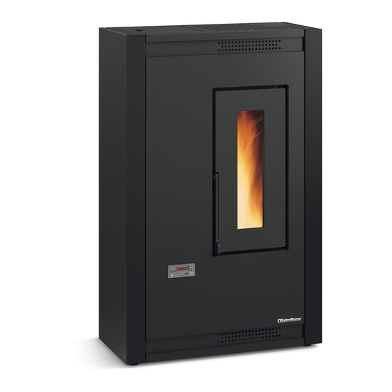
- Page 1 UseR MANUAl LUISELLA MADE ITALY design & production 004276847 - REV001...
- Page 2 ENGLISH...
- Page 3 ENGLISH .........................................5 WarNINGS ......................................5 SafEty ........................................5 routINE MaINtENaNcE ..................................6 INStaLLatIoN .......................................7 General ................................................. 7 DEtaILS of LuISELLa ..................................9 SpacerS ................................................10 FuSe ................................................10 StovE poSItIoNING ..................................11 NotE for corrEct opEratIoN ..............................11 pELLEt HoppEr - prESSurISED cLoSurE ............................. 11 pELLEtS aND fEEDING ..................................12 tHE DISpLay DEScrIptIoN of BaSIc coMMaNDS aND SyMBoLS ...................
- Page 4 ATTENZIONE ! ATENcION! durANTE lA mOvImENTAZIONE dEllA durANTE El dEsplAZAmIENTO dE lA mA- mAcchINA, fArE pArTIcOlArE quINA, TENEr ATTENZIONE AI cOmpONENTI IN dETTA- muchO cuIdAdO A lOs cOmpONENTEs glIO! EN dETAllE. WArNINg! ATENÇÃO ! durINg ThE hANdlINg Of ThE mAchINE, durANTE A mOvImENTAÇÃO dA mÁquI- pAy AccurATE ATTENTION TO ThE cOm- NA, prEsTAr EspEcIAl...
-
Page 5: English
We thank you for having chosen our company; our product is a great heating solution developed from the most advanced technology with top quality machining and modern design, aimed at making you enjoy the fantastic sensation that the heat of a flame gives, in complete safety. Warnings This instructions manual is an integral part of the product: make sure that it always accompanies the appliance, even if transferred to another owner or user, or if transferred to another place. -
Page 6: Routine Maintenance
Š DO NOT LEAVE THE PACKAGING ELEMENTS WITHIN REACH OF CHILDREN OR UNASSISTED DISABLED PERSONS. Š THE HEARTH DOOR MUST ALWAYS BE CLOSED DURING NORMAL FUNCTIONING OF THE PRODUCT. Š WHEN THE APPLIANCE IS FUNCTIONING AND HOT TO THE TOUCH, ESPECIALLY ALL EXTERNAL SURFACES, ATTENTION MUST BE PAID Š... -
Page 7: Installation
InstallatIon general The flue gas exhaust and hydraulic connections must be carried out by qualified personnel who must issue installation conformity documentation compliant with national standards. the installer must provide the owner or person acting for him, according to the legislation in force, with the declaration of conformity, supplied with: 1) the use and maintenance manual of the appliance and of the system components (such as for example, the smoke ducts, chimney, etc.);... - Page 8 In the presence of type B gas appliances with intermittent operation not intended for heating, they must have their own aeration and/or ventilation opening. The air inlets must meet the following requirements: Š they must be protected with grids, metal mesh, etc., but without reducing the net useful section; Š...
-
Page 9: Details Of Luisella
Combustive air Access to combustion chamber Pellet hopper pressurised closure input Display Room air outlet Serial input On/Off Spacer Upper fumes exhaust Fuse Room sensor Rear fumes exhaust Power supply 230v ENGLISH... -
Page 10: Spacers
spACers There are two spacers located on the rear of the machine which determine the minimum distance any support behind the stove. The spacers must not be removed. fuse If there is no power supply to the stove, check the state of the fuse located in the box between the stove switch and the power cable connection. -
Page 11: Stove Positioning
stove positioning To ensure the stove works correctly, it should always be positioned so that it is perfectly level, using a spirit level. note for CorreCt operAtion The following indications must be respected for correct pellet stove operation: Pellet hopper lid During stove operation, both the pellet hopper lid and the door must always be closed. -
Page 12: Pellets And Feeding
Pellets and feeding Pellets are made by applying high pressure to sawdust, or wood waste products (not containing paint) from sawmills, carpentry and other activities related to processing and working with wood. Given that it does not use any glue to hold it together this type of fuel is completely environmentally friendly. -
Page 13: The Display Description Of Basic Commands And Symbols
The Display DescripTion of Basic commanDs anD symBols ON/OFF BUTTON INCREASE SET POWER DECREASE SET POWER INCREASE SET THERMOSTAT DECREASE SET THERMOSTAT Display icons key Indicates the presence of an alarm. On: indicates the presence of an alarm. Off: indicates there are no alarms Flashing: fire door or pellet hopper open Indicates the set temperature status LED on: the stove is reaching the set temperature (room temperature still lower than set temperature) -
Page 14: General Menu
General menu ON/OFF BUTTON - EXIT MENU SCROLL UP - CONFIRM SCROLL DOWN PRESS AND HOLD TO ACCESS MENU - ACCESS SELECTED MENU - INCREASE VALUE DECREASE VALUE (Ventilation) (Speed) EaSY (Pellet calibration) Crno aBiL (Chrono) (Enable) prg1 (PROGRAMMING 1) prg2 (PROGRAMMING 2) daTE... -
Page 15: Remote Control
remoTe conTrol When using the remote control, you can regulate the heating power, room temperature required and switch the device on/off. on/off Prolonged pressure turns the stove on or off. power increase Increases operating power power Decrease Decreases operating power T°... -
Page 16: Commissioning Settings
commissioninG seTTinGs Once the power cable at the back of the generator has been connected, move the switch, also located on the back, to (I). The switch at the back of the generator powers the generator board. The generator remains off and an initial screen appears on the panel, displaying OFF. mains power frequency 50/ 60hz If the generator is installed in a country with a frequency of 60Hz, the generator will display “POWER FREQUENCY ERROR ". -
Page 17: Operation And Logic
operaTion anD loGic iGniTion Once the points listed previously have been checked, press key 1 for three seconds to ignite the stove. There are 15 minutes available to detect the presence of the flame during the ignition phase. When the control temperature is reached, stove interrupts the ignition phase and switches to PREPARATION. -
Page 18: Air (Ventilation)
iT is forBiDDen To use The Device wiThouT a parTiTion (a) anD flame GuarD (B). removal will compromise The safeTy of The proDucT anD resulT in The immeDiaTe nullificaTion of The warranTy perioD. in The evenT of wear or DeTerioraTion, requesT The parT's replacemenT from The afTer-sales service. -
Page 19: Stat (Status)
sTaT (sTaTus) references reserved for the technician crno (chrono) This function allows the stove's ignition and switch-off to be automatically programmed. The factory setting for CHRONO is off. The chrono allows the programming of 4 time slots within a day, which can be used every day of the week. ignition and switch-off times can be set for each time slot, along with the specific days of application for the programmed time slot, the desired temperature and power setting. - Page 20 Crno > aBiL Enables/disables all the set chrono prg1 > aBiL On/Off Enabling/disabling PRG 1 STrT OFF-00:00-23:50 PRG1 start time STop OFF-00:00-23:50 PRG1 stop time daY1...daY7 On/off Enabling/disabling days for PRG1 TEmp LOU - 07- 40 °C - HOT Set thermostat PRG1 poW.
- Page 21 EXampLE of Chrono oVErLapping TimE/SLoTS Time slot 02:00 08:00 16:30 23:00 Power 02:00 08:00 16:30 23:00 Set temperature 22° 18° 02:00 08:00 16:30 23:00 start 02:00 Time slot 1 power 3 - set temp 22°C stop 23:00 start 08:00 Time slot 2 power 1 - set temp 18°C stop 16:30 stove operation...
-
Page 22: Set (Settings)
seT (seTTinGs) Š daTE Š daY Š TimE SEE CHAPTER: COMMISSIONING SETTINGS. Š Lng Š C-f sTBy (sTanD-By) The stand-by function is used if the stove needs to be turned off immediately instead of a power modulation. CONTROLS PROCEDURE Š Press and hold key 4. Š... -
Page 23: Res (Reset)
res (reseT) Allows the user to reset all modifiable values to the default values. CONTROLS PROCEDURE Š Press and hold key 4. Š Press key 3 until SET appears and access with key 4. Š Press key 3 until rES appears and access with key 4. Š... -
Page 24: Cleaning And Maintenance
When the tank is completely empty, disconnect the power cable of the generator and remove the residues first (dust, chippings, etc.) from the empty tank, and then fill it. to find out whErE your nEarEst sErvicE cEntrE is, contact your dEalEr or go to thE wEbsitE: www.lanordica-EXtraflamE.com ENGLISH... - Page 25 every day burn pot and Combustion Chamber: Š Vacuum the residue in the burn pot Š Remove the burn pot completely from the relevant compartment; Š Vacuum the ash from the burn pot slot, ignition plug pipe holder and combustion chamber. Š...
- Page 26 every 30 days Š Remove the cast-iron wall by tilting it (C). Cleaning the tube heat exChanger Š Once the central cast iron wall has been removed, clean the tube heat exchanger (D). Š Vacuum the residue in the burn pot Š...
-
Page 27: Burn Pot Detail
the gaskets for the pellet hopper, burn pot and fire door ensure that the stove works properly. it is neCessary to periodiCally CheCk them; if they seem to be worn or damaged, they must be replaCed immediately. these operations must be Carried out by a qualified teChniCian. a Clean burn pot guarantees CorreCt operation! by making sure the burn pot and its holes are always Clean from any Combustion residue, exCellent Combustion by the generator is... -
Page 28: Routine Maintenance Performed By Qualified Technicians
Routine maintenance must be performed at least once a year. to find out whErE your nEarEst sErvicE cEntrE is, contact your dEalEr or go to thE wEbsitE: www.lanordica-EXtraflamE.com ENGLISH... - Page 29 routine maintenanCe THE IMAGES ARE FOR ILLUSTRATIVE PURPOSES ONLY. THE IMAGES ARE FOR ILLUSTRATIVE PURPOSES ONLY. Fumes motor (disassembly and cleaning and fumes and "T" pipes), new silicone or gasket in the points indicated. Gaskets, pellet hopper and door (replace them and apply silicone where required) Combustion chamber and heat exchanger (full cleaning) including ignition-plug pipe Hopper (complete emptying and cleaning) and check gasket.
- Page 30 routine maintenanCe THE IMAGES ARE FOR ILLUSTRATIVE PURPOSES ONLY. Fumes motor (disassembly and cleaning and fumes and "T" pipes), new silicone or gasket in the points indicated. Gaskets, pellet hopper and door (replace them and apply silicone where required) Combustion chamber and heat exchanger (full cleaning) including ignition-plug pipe Hopper (complete emptying and cleaning) and check gasket.
-
Page 31: Displays
Displays Display Reason Generator off sTaRT The start-up phase is in progress pelleT loaDinG Continuous pellet feeding is in progress during the ignition phase iGniTion The ignition phase is in progress pRepaRaTion The preparation phase is in progress WoRk The normal work phase is in progress MoDulaTion The generator is working at minimum final cleaninG... -
Page 32: Guarantee Terms
Extraflame S.p.A. cannot be held liable for injury or damage which may - either directly or indirectly - be caused to persons, animals and property ensuing from failure to observe all the instructions provided in the relevant instruction manual and the warnings regarding installation, use and maintenance of the product, that can also be downloaded on the website. - Page 33 AddITIONAL wARNINGs Š Only use the fuel recommended by the manufacturer. The product must not be used as an incinerator. Š Do not use the product as a ladder or supporting structure. Š Do not place laundry on the product to dry it. Any clothes-horse or similar objects must be kept at due distance from the product. Danger of fire or damage to the coating.
- Page 34 ENGLISH...
- Page 35 ENGLISH...
- Page 36 Extraflame S.p.A. Via Dell’Artigianato, 12 36030 - MONTECCHIO PRECALCINO (VI) - ITALY +39.0445.865911 - +39.0445.865912 - info@extraflame.it - www.lanordica-extraflame.com MADE ITALY design & production TO FIND THE SERVICE CENTRE NEAREST TO YOU CONTACT YOUR DEALER OR CONSULT THE SITE WWW.LANORDICA-EXTRAFLAME.COM...
Need help?
Do you have a question about the LUISELLA and is the answer not in the manual?
Questions and answers