Table of Contents
Advertisement
Quick Links
Download this manual
See also:
User Manual
Advertisement
Table of Contents

Related Manuals for RuggedCom RSG2488


Summary of Contents for RuggedCom RSG2488
- Page 1 RUGGEDCOM RSG2488 Installation Guide April 5, 2013 www.RuggedCom.com...
- Page 2 RuggedCom has verified the contents of this manual against the hardware and/or software described. However, deviations between the product and the documentation may exist. RuggedCom shall not be liable for any errors or omissions contained herein or for consequential damages in connection with the furnishing, performance, or use of this material.
-
Page 3: Table Of Contents
RUGGEDCOM RSG2488 RUGGEDCOM RSG2488 Installation Guide Table of Contents Preface ........................ Alerts ..............................v Related Documents ..........................v Accessing Documentation ........................vi Training .............................. vi Customer Support ..........................vi Chapter 1 Introduction ......................1.1 Feature Highlights ........................1 1.2 Configuration Ports and Indicator LEDs ..................1 Chapter 2 Installing the Device .................... - Page 4 RUGGEDCOM RSG2488 RUGGEDCOM RSG2488 Installation Guide 3.3 Installing/Removing SFP Optical Ports ..................18 3.3.1 Installing an SFP Optical Port ..................19 3.3.2 Removing an SFP Optical Port ..................19 Chapter 4 Technical Specifications ..................4.1 Power Supply Specifications ....................... 21 4.2 Failsafe Relay Specifications ......................
-
Page 5: Preface
RUGGEDCOM RSG2488 Installation Guide Preface This guide describes the RUGGEDCOM RSG2488. It describes the major features of the device, installation, commissioning and important technical specifications. It is intended for use by network technical support personnel who are responsible for the installation, commissioning and maintenance of the device. -
Page 6: Accessing Documentation
RuggedCom Sales representative. Customer Support Customer support is available 24 hours, 7 days a week for all RuggedCom customers. For technical support or general information, please contact Customer Support at: Toll Free (North America): 1 866 922 7975... -
Page 7: Introduction
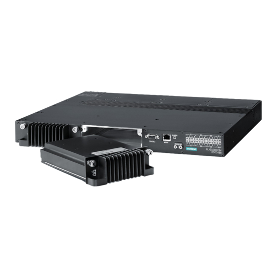
Introduction Introduction The RSG2488 is a utility grade, fully managed, industrial Ethernet switch designed to operate reliably in harsh environments. With rugged metal enclosure and an optional conformal coating, the RSG2488 provides a high level of immunity to electromagnetic interference and heavy electrical surges, and can withstand temperatures between -40 and 85 °C (-40 and 185 °F). - Page 8 Chapter 1 RUGGEDCOM RSG2488 Introduction Installation Guide Figure 1: Front Panel 1. Power Module Indicator LEDs 2. RS232 Serial Console Port 3. Management Port 4. Alarm Indicator LED 5. MicroSD Port 6. Port Status Indicator LEDs RS232 Serial Console Port This port is for interfacing directly with the device and access initial management functions.
-
Page 9: Installing The Device
Mounting the Device The RSG2488 is designed for maximum mounting and display flexibility. It can be ordered with connectors that allow it to be installed in a 48 cm (19 in) rack, 2.5 cm (1 in) DIN rail, or directly on a panel. -
Page 10: Mounting The Device To A Rack
Mounting the Device to a Rack For rack mount installations, the RSG2488 can be ordered with rack mount adaptors pre-installed at the front or rear of the chassis. Additional adaptors are provided to further secure the device in high-vibration or seismically active locations. -
Page 11: Mounting The Device On A Din Rail
Section 2.1.2 Mounting the Device on a DIN Rail For panel installations, the RSG2488 can be ordered with panel/DIN rail adaptors pre-installed on each side of the chassis. The adaptors allow the device to be attached to a panel using screws. -
Page 12: Installing/Removing Power Supplies
Section 2.2 Installing/Removing Power Supplies The RSG2488 supports dual redundant AC and/or DC power supplies that can be installed in any combination. IMPORTANT! • In a high AC/DC and low DC (24/48 V) power supply arrangement, either power supply can be installed in slot PM1 or PM2. -
Page 13: Installing The Power Supplies
RUGGEDCOM RSG2488 Chapter 2 Installation Guide Installing the Device • The socket outlet/disconnect device must be installed near the device and be easily accessible. • Equipment must be installed according to applicable local wiring codes and standards. The following sections describe how to install, remove and wire the power supplies: •... -
Page 14: Wiring Power Supply Terminal Blocks
Wiring Power Supply Terminal Blocks The RSG2488 can be equipped with screw-type or insulated terminal blocks for high or low AC/DC power input. Connect the terminal blocks to the HI and LO terminal ports on the rear face of the device. - Page 15 RUGGEDCOM RSG2488 Chapter 2 Installation Guide Installing the Device CAUTION! Electrical hazard — risk of damage to the device. Do not connect AC power cables to a DC power supply terminal block. Damage to the power supply may occur. Connectors for Power Modules WARNING! Electrocution hazard —...
-
Page 16: Connecting The Failsafe Alarm Relay
Chapter 2 RUGGEDCOM RSG2488 Installing the Device Installation Guide Figure 11: Single DC Power Supply Wiring Figure 12: Dual DC Power Supply Wiring Figure 13: Dual AC/DC Power Supply Wiring Section 2.3 Connecting the Failsafe Alarm Relay The failsafe relay is provided to identify criticial error conditions. The contacts are energized when the device is powered-up and remain energized unless a critical error occurs. -
Page 17: Grounding The Device
Section 2.4 Grounding the Device The RSG2488 chassis ground connection uses a #6-32 screw. It is recommended to terminate the ground connection with a #6 ring or spade lug and torque it to 1.7 Nm (15 lbf-in). Figure 15: Chassis Ground Connection 1. -
Page 18: Protection On Twisted-Pair Data Ports
1 standards. This means that during a transient electrical event, communications erorrs or interruptions may occur, but recovery is automatic. RuggedCom also does not recommend using copper Ethernet ports to interface with devices in the field across distances that could produce high levels of ground potential rise (i.e. greater than 2500 V), during line-to-ground fault conditions. -
Page 19: Connecting To The Device
Section 2.6 Connecting to the Device The RS232 serial console port on the front of the RSG2488 device provides access to the boot-time control and configuration menu interface, as well as a console connection to the ROS™ Web interface. Figure 16: Serial Console Port 1. - Page 20 Chapter 2 RUGGEDCOM RSG2488 Installing the Device Installation Guide Connecting to the Device...
-
Page 21: Modules
Chapter 3 Installation Guide Modules Modules The RSG2488 can be equipped with multiple modules to enhance its abilities and performance. Each type of module has a specific location in the RSG2488 chassis. Figure 17: Module Assignment 1. Front Panel 2. Rear Panel 3. - Page 22 Chapter 3 RUGGEDCOM RSG2488 Modules Installation Guide Ethernet - Copper Figure 18: 4 Port RJ45 Figure 19: 2 Port RJ45 Figure 20: 4 Port FastConnect RJ45 Figure 21: 2 Port FastConnect RJ45 Ethernet - Fiber Figure 22: 4 Port LC...
-
Page 23: Installing/Removing Modules
Upon installing a new module in the device, all the features associated to the module are available in the operating system. For more information, refer to the ROS User Guide for the RSG2488. To install a module, do the following: Make sure power to the device has been disconnected and wait approximately two minutes for any remaining energy to dissipate. -
Page 24: Removing Modules
Section 3.3 Installing/Removing SFP Optical Ports The RSG2488 can be ordered with SFP (Small Form-factor Pluggable) optics modules. The optical ports in these modules can be safely inserted and removed while the chassis is powered and operating. The following sections describe how to install and remove SFP optical ports: •... -
Page 25: Installing An Sfp Optical Port
To install an SFP optical port, do the following: CAUTION! Electrical hazard – risk of damage to equipment. Use only components certified by RuggedCom with RuggedCom products. Damage to the module and device may occur if compatibility and reliability have not been properly assessed. - Page 26 Chapter 3 RUGGEDCOM RSG2488 Modules Installation Guide Grab the metal bail-latch on the port and remove the port from the module. Figure 30: Removing an SFP Optical Port 1. SFP Optical Port 2. Metal Bail-Latch Immediately insert a dust cover in the empty port slot to prevent the ingress of dust and dirt.
-
Page 27: Technical Specifications
RUGGEDCOM RSG2488 Chapter 4 Installation Guide Technical Specifications Technical Specifications The following sections provide important technical specifications related to the device and available modules: • Section 4.1, “Power Supply Specifications” • Section 4.2, “Failsafe Relay Specifications” • Section 4.3, “Port Specifications”... -
Page 28: Port Specifications
500 VA Section 4.3 Port Specifications The following details the specifications for fibre optic ports that can be ordered with the RSG2488. NOTE • Maximum segment length is greatly dependent on factors such as fiber quality, and the number of patches and splices. -
Page 29: Supported Networking Standards
RUGGEDCOM RSG2488 Chapter 4 Installation Guide Technical Specifications Cable Tx λ Distance Power Order Connector Tx min Tx max Mode Type (typ.) Sensitivity Saturation (Typ.) Budget Code Type (dBm) (dBm) (μm) (nm) (dBm) (dBm) (km) (dB) FG52 9/125 1310 -9.5... -
Page 30: Mechanical Specifications
Chapter 4 RUGGEDCOM RSG2488 Technical Specifications Installation Guide Section 4.6 Mechanical Specifications Table 8: Mechanical Specifications Parameter Value Dimensions Refer to Chapter 5, Dimension Drawings Weight 8.6 kg (19 lbs) Enclosure 18 AWG Galvanized Steel Section 4.7 Pin Assignments RS232 Serial Console Port... - Page 31 RUGGEDCOM RSG2488 Chapter 4 Installation Guide Technical Specifications Terminal Blocks Terminal Block Description PS1/PS2 L+ Connected to the (Live) terminal. PS1/PS2 N- Connected to the (Neutral) terminal. Relay NO Normally open failsafe relay contact. Relay COM Failsafe relay common contact.
- Page 32 Chapter 4 RUGGEDCOM RSG2488 Technical Specifications Installation Guide Pin Assignments...
-
Page 33: Dimension Drawings
RUGGEDCOM RSG2488 Chapter 5 Installation Guide Dimension Drawings Dimension Drawings NOTE All dimensions are in millimeters, unless otherwise stated. 442.4 Figure 34: Overall Dimensions... - Page 34 Chapter 5 RUGGEDCOM RSG2488 Dimension Drawings Installation Guide 483.5 465.2 21.1 Figure 35: Rack Mount Dimensions...
- Page 35 RUGGEDCOM RSG2488 Chapter 5 Installation Guide Dimension Drawings 480.5 490.6 Figure 36: Panel and Din Rail Mount Dimensions 1. DIN Rail Centerline...
- Page 36 Chapter 5 RUGGEDCOM RSG2488 Dimension Drawings Installation Guide...
-
Page 37: Certification
RUGGEDCOM RSG2488 Chapter 6 Installation Guide Certification Certification The RSG2488 device has been thoroughly tested to guarantee its conformance with recognized standards and has recieved approval from recognized regulatory agencies. • Section 6.1, “Agency Approvals” • Section 6.2, “FCC Compliance”... -
Page 38: Emi And Environmental Tests
Chapter 6 RUGGEDCOM RSG2488 Certification Installation Guide Section 6.3 EMI and Environmental Tests The RSG2488 has passed the following EMI and environmental tests. Table 10: IEC 61850-3 EMI Type Tests Test Description Test Levels Severity Levels Enclosure Contact +/- 8 kV... - Page 39 RUGGEDCOM RSG2488 Chapter 6 Installation Guide Certification Test Description Test Levels Severity Levels 5 kV (Fail-Safe Signal Ports Relay Output) H.V. Impulse D.C. Power Ports 5 kV A.C. Power Ports 5 kV (Fail-Safe Signal Ports Relay Output) Dialiectric Strength D.C. Power Ports 5 kV A.C.
- Page 40 Chapter 6 RUGGEDCOM RSG2488 Certification Installation Guide EMI and Environmental Tests...
Need help?
Do you have a question about the RSG2488 and is the answer not in the manual?
Questions and answers