Table of Contents
Advertisement
Quick Links
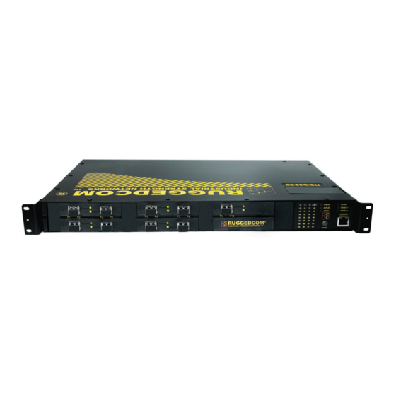
RuggedSwitch™ ™ ™ ™ RSG2200
RuggedSwitch
RuggedSwitch
RuggedSwitch
9-Port Modular Managed Gigabit Ethernet Switch
Installation Guide
RuggedCom Inc. I 30 Whitmore Road, Woodbridge, Ontario, Canada L4L 7Z4
Tel: (905) 856-5288 I Fax: (905) 856-1995 I Toll Free: (888) 264-0006
RSG2200
RSG2200
RSG2200
www.ruggedcom.com
Advertisement
Table of Contents

Subscribe to Our Youtube Channel
Related Manuals for RuggedCom RuggedSwitch RSG2200


Summary of Contents for RuggedCom RuggedSwitch RSG2200
-
Page 1: Installation Guide
RuggedSwitch™ ™ ™ ™ RSG2200 RSG2200 RSG2200 RSG2200 9-Port Modular Managed Gigabit Ethernet Switch Installation Guide www.ruggedcom.com RuggedCom Inc. I 30 Whitmore Road, Woodbridge, Ontario, Canada L4L 7Z4 Tel: (905) 856-5288 I Fax: (905) 856-1995 I Toll Free: (888) 264-0006... - Page 2 This product contains no user serviceable parts. Attempted service by unauthorized personnel shall render all warranties null and void. Changes or modifications not expressly approved by RuggedCom Inc. could void the user’s authority to operate the equipment.
-
Page 3: Table Of Contents
Twisted-Pair Port Specifications............... 27 Fiber Optical Specifications................28 5.5.1 Gigabit Ethernet (1000Mbps) Modules ............ 28 Type Test Specifications................... 30 Operating Environment..................31 Mechanical Specifications ................32 Agency Approvals ......................... 33 Warranty..........................33 © 2008 RuggedCom Inc. All rights reserved Rev105... -
Page 4: Table Of Figures
Table 3: RSG2200 Power terminal block connection description........... 16 Table 4: RS232 over RJ45 console cable pin-out ................. 22 Table 5: Cabling categories and 1000BaseTx compliance defined..........23 Table 6: Gigabit port optical specifications..................28 © 2008 RuggedCom Inc. All rights reserved Rev105... -
Page 5: Product Overview
(SFP, GBIC, LC, SC) without loss of port density. The RSG2200 is packaged in a rugged galvanized steel enclosure with industrial grade DIN, panel, or 19" rack mount mounting options. © 2008 RuggedCom Inc. All rights reserved Rev105... -
Page 6: Feature Highlights
Simple Plug and Play Operation • Automatic learning of up to 8192 MAC addresses • Auto-negotiation on all 10/100/1000BaseTX ports • Auto-MDI/MDIX (crossover) on all 10/100BaseTX ports • LED indicators for link, activity and speed © 2008 RuggedCom Inc. All rights reserved Rev105... - Page 7 • Port configuration, status, statistics, mirroring, security • Loss of link management on fiber ports • Web-based, Telnet, CLI management interfaces • SNMP v2 and RMON • Rich set of diagnostics with logging and alarms © 2008 RuggedCom Inc. All rights reserved Rev105...
-
Page 8: Mounting Flexibility
See Figure 1 for rack mount orientation examples. Figure 1: RSG2000 Rack mount chassis orientation options – Front and rear mount. © 2008 RuggedCom Inc. All rights reserved Rev105... -
Page 9: Ethernet Panel Description
LED will be solid for ports with link, and will blink for activity. The diagram in Figure 3 highlights the port and the associated link/activity LED. Figure 3: Ethernet panel LED description © 2008 RuggedCom Inc. All rights reserved Rev105... -
Page 10: Fiber Optical Transceiver Orientation And Connection
(ie RX and TX will be reversed). Figure 4: 1000LX SFP (mini-GBIC) Module and Figure 5: 1000LX GBIC connector LC connector Figure 7: 1000LX SC connector Figure 6: 1000LX LC connector © 2008 RuggedCom Inc. All rights reserved Rev105... -
Page 11: Display Panel Description
• Power supply and Alarm status indicators • Convenient port status indicators conveying Link-Activity, Duplex, or Speed via push- button control. • System reset via push-button if held for 5 seconds Figure 9: RSG2200 LED Display Panel © 2008 RuggedCom Inc. All rights reserved Rev105... -
Page 12: Table 1: Led Display – Device Status Led Behavior Definition
Activity No link Green (Solid) Full-Duplex operation Duplex Orange (Solid) Half-Duplex operation No link Green (Blinking) 1000Mb/s Green (Solid) 100Mb/s Speed Orange (Solid) 10Mb/s No link Table 2: Port Status behavior definition © 2008 RuggedCom Inc. All rights reserved Rev105... -
Page 13: Installation
Although forced airflow is not necessary, any increase in airflow will result in a reduction of ambient temperature that will improve long-term reliability of all equipment mounted within the rack space. © 2008 RuggedCom Inc. All rights reserved Rev105... -
Page 14: Panel And Din Rail Mounting
The adapter allows for the chassis to be mounted on the standard 1” DIN rail using the grooves in the adapter, secured using the included Philips screw. See Figure 12 for a PANEL/DIN mount diagram. Figure 12: RSG2200 PANEL/DIN RAIL mounting diagram with © 2008 RuggedCom Inc. All rights reserved Rev105... -
Page 15: Power Supply Wiring And Grounding
The safety cover must be re-attached after wiring to ensure personnel safety. Refer to Table 3 below for a description of each terminal as well as sections 4.3.1 through 4.3.3 for wiring examples. © 2008 RuggedCom Inc. All rights reserved Rev105... -
Page 16: Table 3: Rsg2200 Power Terminal Block Connection Description
AC. Relay NO Contact Normally open, failsafe relay contact. Relay Common Failsafe relay common contact. Relay NC Contact Normally closed, failsafe relay contact. Table 3: RSG2200 Power terminal block connection description © 2008 RuggedCom Inc. All rights reserved Rev105... -
Page 17: Ac Power Supply Wiring Examples
2. Equipment must be installed according to the applicable country wiring codes. 3. When equipped with two HI voltage power supplies, independent AC sources can be used to power the product for greater redundancy. © 2008 RuggedCom Inc. All rights reserved Rev105... -
Page 18: Dc Power Supply Wiring Examples
2. A circuit breaker is not required for 12, 24 or 48 VDC rated power supplies. 3. For dual DC power supplies, Separate circuit breakers must be installed and separately identified. 4. Equipment must be installed according to the applicable country wiring codes. © 2008 RuggedCom Inc. All rights reserved Rev105... -
Page 19: Dual Power Supplies - Dc And Ac Inputs
3. A circuit breaker is not required for 48 or 24VDC rated power supplies. 4. Separate circuit breakers must be installed and separately identified. 5. Equipment must be installed according to the applicable country wiring codes. © 2008 RuggedCom Inc. All rights reserved Rev105... -
Page 20: Dielectric Strength (Hipot) Testing
HIPOT testing. Figure 18 shows the proper HIPOT test connections and should be followed to avoid damage to the device. Figure 18: Dielectric Strength (HIPOT) Testing © 2008 RuggedCom Inc. All rights reserved Rev105... -
Page 21: Failsafe Alarm Relay Wiring And Specifications
The proper relay connections are shown in Figure 19. One common application for this output is to signal an alarm if a power failure or removal of control power occurs. Figure 19: Failsafe Alarm Relay Wiring © 2008 RuggedCom Inc. All rights reserved Rev105... -
Page 22: Console Port Wiring
Figure 20: Console port location on display board Figure 21: RSG2200 Console cable For user reference, the console cable pin-out is show in Table 5. RuggedCom RS232 over RJ45 pin-out specification Signal Name (PC is DTE) DB9- Female RJ45 Male DCD –... -
Page 23: Gigabit Ethernet 1000Base-Tx Cabling Recommendations
• Shielded/screened cabling can optionally be used. The cable shield should be grounded at one single point to avoid the generation of ground loops. NOTE: RuggedCom does not recommend the use of copper cabling of any length for critical real- time substation automation applications. However, transient suppression circuitry is present on all copper ports to protect against damage from electrical transients and to ensure IEC 61850-3 and IEEE 1613 Class 1 conformance. -
Page 24: Pluggable Optics - Installation, Removal, And Precautions
• Disconnect all cables from SFP or GBIC module before insertion or removal of module. • Only RuggedCom Inc. certified optics should be used on RuggedCom products. Damage can occur to optics and product if compatibility and reliability have not been properly assessed. -
Page 25: Gbic Module Removal
SFP module. Removal of the SFP module is shown further in Figure 25. The module should be immediately stored in an ESD-safe environment. Figure 25: SFP Removal Figure 24: SFP Bail Latch location © 2008 RuggedCom Inc. All rights reserved Rev105... -
Page 26: Technical Specifications
10BaseT / 10BaseFL IEEE 802.3u 100BaseTX / 100BaseFX IEEE 802.3z 1000BaseSX/LX IEEE 802.3ab 1000BaseTx IEEE 802.3x Full Duplex Operation IEEE 802.1D MAC Bridges IEEE 802.1Q VLAN (Virtual LAN) IEEE 802.1p Priority Levels © 2008 RuggedCom Inc. All rights reserved Rev105... -
Page 27: Twisted-Pair Port Specifications
Parameter Specification Notes Speed 10/100 Mbps Auto-negotiating Duplex FDX / HDX Auto-negotiating Cable-Type > Category 5 Shielded/Unshielded Wiring Standard TIA/EIA T568A/B Auto-Crossover, Auto-polarity Max Distance 100m Connector RJ45 Isolation 1.5kV RMS 1-minute © 2008 RuggedCom Inc. All rights reserved Rev105... -
Page 28: Fiber Optical Specifications
Gigabit Ethernet (1000Mbps). 5.5.1 Gigabit Ethernet (1000Mbps) Modules For maximum flexibility RuggedCom Inc. offers a number of different transceiver choices for Gigabit fiber optical communications. Table 6 details fiber optic specifications based on the 2-port modules or pluggable transceivers selected at time of ordering. - Page 29 4. These transceivers utilize a distributed feedback (DFB) type laser and are rated for -20°C to +85°C operation only. 5. The 25-10-0108 SFP module is obsolete, and has been replaced with the 70km 25-10-0109 SFP module. © 2008 RuggedCom Inc. All rights reserved Rev105...
-
Page 30: Type Test Specifications
Temperature (Dry Cold) -40°C Test Ad: 16 hrs @ -40°C IEC 60068-2-2 Temperature (Dry Heat) 85°C Test Bd: 16 hrs @ 85°C IEC 60068-2-30 Humidity non-condensing Test Db: 6 cycles, 55°C, 95% Humidity © 2008 RuggedCom Inc. All rights reserved Rev105... -
Page 31: Operating Environment
Ambient Temperature as measured from a 30cm Ambient Operating radius surrounding the -40 to 85°C Temperature center of the RS1600 enclosure. Ambient Relative Humidity 5% to 95% Non-condensing Ambient Storage -40 to 85°C Temperature © 2008 RuggedCom Inc. All rights reserved Rev105... -
Page 32: Mechanical Specifications
18.29 x 12.14 x 1.75 inches (Length x Width x Height) with mounting brackets (464,57) x (308,356) x (44,45) mm installed Weight 10 lb (4.5 Kg) Enclosure 18awg galvanized steel Figure 26: RSG2200 Series mechanical dimensions © 2008 RuggedCom Inc. All rights reserved Rev105... -
Page 33: Agency Approvals
IEC/EN EN60825-1:1994 + A11:1996 + A2:2001 Compliant 7 Warranty RuggedCom warrants this product for a period of five (5) years from date of purchase. For warranty details, visit http://www.ruggedcom.com/ or contact your customer service representative. Should this product require warranty or service contact the factory at: RuggedCom Inc.
Need help?
Do you have a question about the RuggedSwitch RSG2200 and is the answer not in the manual?
Questions and answers