RuggedCom RuggedSwitch RS940G Installation Manual
8-port managed gigabit ethernet switch
Hide thumbs
Also See for RuggedSwitch RS940G:
- Specification sheet (9 pages) ,
- Specification sheet (8 pages)
Table of Contents

Related Manuals for RuggedCom RuggedSwitch RS940G


Summary of Contents for RuggedCom RuggedSwitch RS940G
- Page 1 RuggedSwitch® RS940G 8-Port Managed Gigabit Ethernet Switch Installation Guide www.ruggedcom.com RuggedCom Inc. I 30 Whitmore Road, Woodbridge, Ontario, Canada L4L 7Z4 Tel: (905) 856-5288 I Fax: (905) 856-1995 I Toll Free: (888) 264-0006...
- Page 2 We have checked the contents of this manual against the hardware and software described. However, deviations from the description cannot be completely ruled out. RuggedCom shall not be liable for any errors or omissions contained herein or for consequential damages in connection with the furnishing, performance, or use of this material.
- Page 3 RuggedCom RuggedSwitch RS940G Installation Guide rev101 ®...
-
Page 4: Table Of Contents
Networking Standards Supported....................21 Twisted-Pair Port Specifications....................21 Mechanical Specifications......................21 Type Tests............................23 IEC 61850-3 Type Tests ......................23 IEEE 1613 Type Tests ....................... 25 IEC Environmental Type Tests ....................25 Warranty ............................26 RuggedCom RuggedSwitch RS940G Installation Guide rev101 ® ®... - Page 5 Table 8- Twisted-Pair Port Specifications ....................21 Table 9 - Mechanical Specifications......................21 Table 10 - IEC 61850-3 Type Tests ......................23 Table 11 - IEEE 1613 Type Tests ......................25 Table 12 - Environmental Type Tests....................... 25 RuggedCom RuggedSwitch RS940G Installation Guide rev101 ® ®...
-
Page 6: Product Overview
6 - 10/100/1000BaseTX Triple Speed Copper Ports Standard o Optional 2 additional 1000LX SFP Pluggable Gigabit Fiber or 2 additional 10/100/1000BaseTX Copper Ports o Bi-directional singlestrand fiber support o Long haul optics allow Gigabit distances up to 70km RuggedCom RuggedSwitch RS940G Installation Guide rev101 ® ®... -
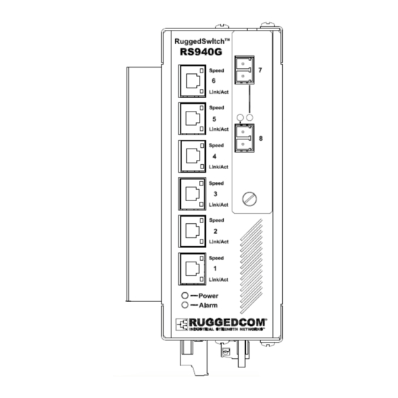
Page 7: Rs940G Front Panel Description
1.3 RS940G Front Panel Description Figure 1 - RS940G Front Panel Description Status LED Colour Activity Comments Power LED Green Solid Power On Alarm LED Solid Alarm condition exists Table 1 - Status LEDs RuggedCom RuggedSwitch RS940G Installation Guide rev101 ® ®... -
Page 8: Rs940G Bottom Panel Description
Product Overview 1.4 RS940G Bottom Panel Description Console Port Chassis Ground Power Port Failsafe Relay Optional Din-Rail Mounting Bracket Figure 2 - RS940G Bottom Panel Description RuggedCom RuggedSwitch RS940G Installation Guide rev101 ® ®... -
Page 9: Installation
2.1 Din Rail Mounting An optional DIN rail mounting bracket is available for the RS940G. The figure below details mounting instructions for the standard 1” DIN Rail. Figure 3 - RS940G DIN Rail Mounting RuggedCom RuggedSwitch RS940G Installation Guide rev101 ®... -
Page 10: Power Supply Wiring And Grounding
2. All line-to-ground transient energy is shunted to the Surge Ground terminal. In cases where users require the inputs to be isolated from ground, remove the ground braid between Surge and Chassis Ground. Note that all line-to-ground transient protection circuitry will be disabled. RuggedCom RuggedSwitch RS940G Installation Guide rev101 ®... -
Page 11: Figure 5 - Dc Power Supply Wiring And Grounding Diagram
2. All line-to-ground transient energy is shunted to the Surge Ground terminal. In cases where users require the inputs to be isolated from ground, remove the ground braid between Surge and Chassis Ground. Note that all line-to-ground transient protection circuitry will be disabled. RuggedCom RuggedSwitch RS940G Installation Guide rev101 ®... -
Page 12: Figure 6 - Dielectric Strength Testing
This is required in order to prevent the surge suppression circuitry, which is connected to surge ground, from being activated. Figure 6 - Dielectric Strength Testing RuggedCom RuggedSwitch RS940G Installation Guide rev101 ®... -
Page 13: Failsafe Output Wiring
The behavior of the failsafe relay is configurable via the RuggedSwitch Operating System. Consult the RuggedSwitch Users Guide for details. Figure 7 - RS940G Failsafe Output Relay RuggedCom RuggedSwitch RS940G Installation Guide rev101 ®... -
Page 14: Rs232 Console Port Wiring
Figure 8 - RS232 DCE pin-out NOTE: This port is not intended to be a permanent connection and the cable length should not exceed 2m (6.5 feet). Pins 1,4,6 are connected internally, and pins 7, 8 are connected internally. RuggedCom RuggedSwitch RS940G Installation Guide rev101 ®... -
Page 15: Gigabit Ethernet
Shielded/screened cabling can optionally be used. The cable shield should be grounded at one single point to avoid the generation of ground loops. NOTE: RuggedCom does not recommend the use of copper cabling of any length for critical real- time substation automation applications. However, transient suppression circuitry is present on all copper ports to protect against damage from electrical transients and to ensure IEC 61850-3 and IEEE 1613 Class 1 conformance. -
Page 16: Figure 9: 1000Lx Sfp (Mini-Gbic) Module And Lc Connector
The drawings in the following figures show each fiber optical connector style with a side and top view to allow the user to identify the proper cable connection orientation. Figure 9: 1000LX SFP (mini-GBIC) Module and LC Figure 10: 1000LX SC connector connector Figure 11: 1000LX LC connector RuggedCom RuggedSwitch RS940G Installation Guide rev101 ® ®... - Page 17 Disconnect all cables from SFP or GBIC module before insertion or removal of module. Only RuggedCom Inc. certified optics should be used on RuggedCom products. Damage can occur to optics and product if compatibility and reliability have not been properly assessed.
-
Page 18: Ethernet Panel Description
The LED will be solid for ports with link, and will blink for activity. The diagram in Figure 15 highlights the port and the associated link/activity LED. Figure 15: Fiber Port LED Description Status LED Colour Activity Comments 10/100 Mbps Speed LED Yellow 1000 Mbps RuggedCom RuggedSwitch RS940G Installation Guide rev101 ® ®... -
Page 19: Table 3 - Rj45 Ethernet Port 9 Led Description
Installation Solid Link Established Link/Act LED Yellow Blinking Tx/Rx Activity Table 3 – RJ45 Ethernet port 9 LED description RuggedCom RuggedSwitch RS940G Installation Guide rev101 ® ®... -
Page 20: Technical Specifications
3.3 Failsafe Relay Specifications Load Circuit SELV TNV-2 MAX operating Voltage 30VDC 30 VAC 80VDC MAX operating Current 0.5A 0.3A Isolation (between coil and contacts) 1800 V Table 6 - Failsafe Relay Specifications RuggedCom RuggedSwitch RS940G Installation Guide rev101 ® ®... -
Page 21: Networking Standards Supported
Parameter Value Dimensions 16.8 x 11.7 x 6.6 cm / 6.6 x 4.6 x 2.6 inches Weight 1.2 kg / 2.7 lbs Enclosure 20 AWG Galvanized Steel Table 9 - Mechanical Specifications RuggedCom RuggedSwitch RS940G Installation Guide rev101 ® ®... - Page 22 Technical Specifications RuggedCom RuggedSwitch RS940G Installation Guide rev101 ® ®...
-
Page 23: Type Tests
D.C. Power ports 2kVac Strength A.C. Power ports 2kVac Signal ports 5kV (Fail-Safe Relay output) IEC 60255-5 H.V. Impulse D.C. Power ports A.C. Power ports Table 10 - IEC 61850-3 Type Tests RuggedCom RuggedSwitch RS940G Installation Guide rev101 ® ®... - Page 24 Type Tests RuggedCom RuggedSwitch RS940G Installation Guide rev101 ® ®...
-
Page 25: Ieee 1613 Type Tests
95% (non-condensing), 55 deg C, 6 cycles Cyclic) IEC 60255-21-1 Vibration Tests Fc 2g @ (10-150) Hz Class 2 IEC 60255-21-2 Shock Tests Ea 30g @ 11ms Class 2 Table 12 - Environmental Type Tests RuggedCom RuggedSwitch RS940G Installation Guide rev101 ® ®... -
Page 26: Warranty
Warranty 5 Warranty RuggedCom warrants this product for a period of five (5) years from date of purchase. For warranty details, visit http://www.ruggedcom.com or contact your customer service representative. Should this product require warranty or service contact the factory at: RuggedCom Inc.
Need help?
Do you have a question about the RuggedSwitch RS940G and is the answer not in the manual?
Questions and answers