
Related Manuals for Advantech AIMB-205


Summary of Contents for Advantech AIMB-205
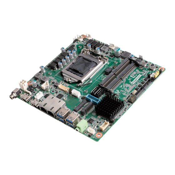
- Page 1 User Manual AIMB-205 Intel® Core™ i7/i5/i3/Pentium/ Celeron LGA1151 Mini-ITX with CRT/DVI-D/DP++/LVDS(or eDP), 8 COM & 14 USB, Dual LAN, PCIe...
- Page 2 The documentation and the software included with this product are copyrighted 2017 by Advantech Co., Ltd. All rights are reserved. Advantech Co., Ltd. reserves the right to make improvements in the products described in this manual at any time without notice.
- Page 3 Advantech has come to be known. Your satisfaction is our primary concern. Here is a guide to Advantech’s cus- tomer services.
-
Page 4: Declaration Of Conformity
Caution! There is a danger of a new battery exploding if it is incorrectly installed. Do not attempt to recharge, force open, or heat the battery. Replace the battery only with the same or equivalent type recommended by the man- ufacturer. Discard used batteries according to the manufacturer's instructions. AIMB-205 User Manual... - Page 5 K4A4G085WD SEC 546 DDR4 2133 16GB Transcend TS2GSH64V1B K4A8G08 5WB BCRC AQD- AD4S2400J4G1 DDR4 2400 16GB ADATA H5ANG8NAFR SD4U16N24- 7-BHYA AQD- ADS240038G17- DDR4 2400 ADATA H5AN8G8NAFR SD4U8GN24- BHYA AQD- AQD- H5AN8G8NAFR DDR4 2400 16GB Advantech SD4U16N24- SD4U16N24-HE AIMB-205 User Manual...
-
Page 6: Ordering Information
Because of Advantech’s high quality-control standards and rigorous testing, most of our customers never need to use our repair service. If an Advantech product is defec- tive, it will be repaired or replaced at no charge during the warranty period. For out- of-warranty repairs, you will be billed according to the cost of replacement materials, service time and freight. - Page 7 It should be free of marks and scratches and in perfect working order upon receipt. As you unpack the AIMB-205, check it for signs of ship- ping damage. (For example, damaged box, scratches, dents, etc.) If it is damaged or it fails to meet the specifications, notify our service department or your local sales representative immediately.
- Page 8 AIMB-205 User Manual viii...
-
Page 9: Table Of Contents
Figure 1.1 Jumper and Connector Location (Top Side)....5 Figure 1.2 Jumper and Connector Location (Bottom Side) ..6 AIMB-205 Board Diagram ................. 7 Figure 1.3 AIMB-205 Board Diagram .......... 7 Safety Precautions ..................7 Jumper Settings ..................8 1.8.1 How to Set Jumpers.............. - Page 10 Software Introduction & Service ..99 Introduction ................... 100 Value-Added Software Services ............100 4.2.1 Software API................100 4.2.2 Software Utility................102 Chapter Chipset Software Installation Utility..Before You Begin.................. 104 Introduction ................... 104 Chapter USB Setup ........105 AIMB-205 User Manual...
- Page 11 COM1 ~ COM4 box header (COM1234)..........134 A.38 Watchdog timer output and OBS beep (JWDT1+ JOBS1)....134 A.39 EDP/LVDS Backlight inverter power connector (INV1)......135 A.40 CMOS battery connector (BAT1) ............135 A.41 COM1 RI# selection pin header (JSETCOM1_V1) ....... 135 AIMB-205 User Manual...
- Page 12 A.42 Serial ATA interface connector (SATA1 / SATA2 ) ....... 136 AIMB-205 User Manual...
-
Page 13: Chapter 1 General Information
Chapter General Information... -
Page 14: Introduction
Introduction AIMB-205 is designed with the Intel® H110 PCH for industrial applications that require both performance computing and enhanced power management capabilities. The motherboard supports Intel desktop Corei7/i5/i3/Pentium/Celeron processor up to 8 MB L3 cache and 2 DDR4 2400MHz SO-DIMM, up to 32 GB. A rich I/O connec- tivity of 8 serial ports, 14 USB, dual GbE LAN, 2 SATA, 1 miniPCIe and 1 NGFF (M.2_B Key) Connector. -
Page 15: Input/Output
+3.3V @ 1.42A, +12V @ 7.53A, -12V @ 0.01A, 5VSB @ 0.43A Measure the maximum current value which system under maximum load (CPU: Top speed, RAM & Graphic: Full loading) Board size: 170 mm x 170 mm (6.69" x 6.69") Board weight: 0.365 kg AIMB-205 User Manual... -
Page 16: Jumpers And Connectors
Jumpers and Connectors Connectors on the AIMB-205 motherboard link it to devices such as hard disk drives and a keyboard. In addition, the board has a number of jumpers used to configure your system for your application. The tables below list the function of each of the board jumpers and connectors. Later sections in this chapter give instructions on setting jumpers. -
Page 17: Board Layout: Jumper And Connector Locations
JWDT1+JOBS1 JLVDS_VCON1 PCIEX16_1 EDP1 INV1 LPC1 BAT1 COM1234 M.2_2 GPIO1 MINI-PCIE1 CPU1 JCASE1 PSON1 SPI1 JCMOS1 COM5678 JCASEOP_SW1 SPI_CN1 USB1112 DIMMA1 CPUFAN1 USB1314 SYSFAN1 SYSFAN2 DIMMB1 JFP1 JFP2 ATXPWR1 Figure 1.1 Jumper and Connector Location (Top Side) AIMB-205 User Manual... -
Page 18: Figure 1.2 Jumper And Connector Location (Bottom Side)
Figure 1.2 Jumper and Connector Location (Bottom Side) AIMB-205 User Manual... -
Page 19: Aimb-205 Board Diagram
1 x RS-232/422/485 PS/2 , WDT, NCT6106D 8-bit GPIO Figure 1.3 AIMB-205 Board Diagram Safety Precautions Warning! Always completely disconnect the power cord from chassis whenever you work with the hardware. Do not make connections while the power is on. Sensitive electronic components can be damaged by sudden power surges. -
Page 20: Jumper Settings
1.8.2 CMOS Clear (JCMOS1) The AIMB-205 motherboard contains a jumper that can erase CMOS data and reset the system BIOS information. Normally this jumper should be set with pins 1-2 closed. If you want to reset the CMOS data, set CMOS1 to 2-3 closed for just a few seconds, and then move the jumper back to 1-2 closed. -
Page 21: Power Led And Keyboard Lock Pin Header (Jfp2)
(2 and 3)+(4 and 5) Watchdog Timer Disable (1-2) OBS BEEP(4-5) (Default) (1 and 2)+(4 and 5) 1.8.6 ATX/AT Mode Selection (PSON1) Table 1.7: ATX/AT Mode Selection (PSON1) Function Jumper Setting AT Mode 1-2 closed ATX Mode (Default) 2-3 closed AIMB-205 User Manual... -
Page 22: Lvds/Edp Panel Voltage Selection (Jlvds1)
5 and 6 System Memory AIMB-205 has two sockets for a 260 pins DDR4 SO-DIMM. This socket uses a 1.2 V unbuffered double data rate synchronous DRAM (DDR SDRAM). DRAM is available in capacities of 4GB, 8GB and 16GB. The sockets can be filled in any combination with SODIMMs of any size, giving a total memory size between 4GB, 8GB, 16GB, and up to max 32GB. -
Page 23: Memory Installation Procedures
1.11 Cache Memory The AIMB-205 supports a CPU with one of the following built-in full speed Last Level Cache: 8MB for Intel Core i7-7700 / i7-7700T / i7-6700 / i7-6700TE 6MB for Intel Core i5-7500 / i5-7500T / i5-6500 / i5-6500TE... - Page 24 AIMB-205 User Manual...
-
Page 25: Chapter 2 Connecting Peripherals
Chapter Connecting Peripherals... -
Page 26: Introduction
USB Ports (LAN1_USB12/LAN2_USB34/USB56/ USB78/USB910) The AIMB-205 provides up to 14 USB ports. Four USB3.0 and four USB2.0 on the rear side and six USB2.0 pin header on the board. The USB interface complies with the USB specification revision 2.0 that supports transmission rates of up to 480 Mbps, revision 3.0 that supports transmission rates of up to 5 Gbps, and is also fuse... -
Page 27: Vga + Dvi-D Connector (Vga1 + Dvi1)
VGA + DVI-D Connector (VGA1 + DVI1) DVI‐D The AIMB-205 includes VGA interface that can drive conventional VGA displays. VGA1 is a standard 15-pin D-SUB connector commonly used for VGA. Serial Ports (COM1~COM8) COM1234 COM5678 AIMB-205 supports eight serial ports, COM1, COM3~8 support RS-232 function, COM2 supports RS-232/422/485 function by BIOS selection. -
Page 28: Ps/2 Keyboard And Mouse Connector (Kbms1)
PS/2 Keyboard and Mouse Connector (KBMS1) On board 6-pin wafer box connector, supports one standard PS/2 keyboard, one standard PS/2 mouse. CPU Fan Connector (CPU_FAN1) If a fan is used, this connector supports cooling fans of 500 mA (6 W) or less. AIMB-205 User Manual... -
Page 29: System Fan Connector (Sysfan1/2)
Power Switch/HDD LED/SMBUS/Speaker Pin Header (JFP1) & Power LED and Keyboard Lock Pin Header (JFP2) There are several headers for monitoring and controlling the AIMB-205. 2.8.1 ATX soft power switch (JFP1/PWR_SW) If your computer case is equipped with an ATX power supply, you should connect the power on/off button on your computer case to (JFP1/ PWR_SW),... -
Page 30: Reset (Jfp1/Reset)
2.8.4 External speaker (JFP1/SPEAKER) JFP1/SPEAKER is a 4-pin connector for an external speaker. If there is no external speaker, the AIMB-205 provides an onboard buzzer as an alternative. To enable the buzzer, set pins 7 & 10 as closed. 2.8.5 Power LED and keyboard lock connector (JFP2/PWR_LED &... -
Page 31: Display Port Connector (Dp1)
Display Port Connector (DP1) DISPLAY PORT_20H DISPLAY PORT20P 2.10 ATX 12V Power Supply Connector (ATX12V1) & ATX Power Supply Connector (ATXPWR1) ATXPWR1 ATX_10x2V_4.2mm ATX10x2P-4.2 AIMB-205 User Manual... -
Page 32: Sata Signal Connector (Sata1 ~ Sata2)
2.11 SATA Signal Connector (SATA1 ~ SATA2) AIMB-205 features a high performance Serial ATA III interface (up to 600 MB/s) which eases hard drive cabling with thin, space-saving cables. 2.12 HD Analog Audio Interface (AUDIO1, FPAUD1) Front headphone connector (FPAUD1) is for a chassis-mounted front panel audio I/O module that supports HD Audio (optional). -
Page 33: Pci-E X16 Slot (Pciex16_1)
2.13 PCI-E x16 Slot (PCIEX16_1) AIMB-205 provides 1 x PCI express x16 slot. 2.14 LVDS Panel Connector (LVDS1) L VD S1 W B_2 0X2 V_ S1.2 5m m W B20 x2P-S1. 25 LVDS1 Pin 3 : GND Panel connected. AIMB-205 User Manual... -
Page 34: Lvds/Edp Backlight Inverter Power Connector (Inv1)
2.15 LVDS/eDP Backlight Inverter Power Connector (INV1) Note! Signal Description Signal Signal Description Vadj=0.75 V (Recommended: 4.7 K, 1/16 W) ENBKL LCD backlight ON/OFF control signal) AIMB-205 User Manual... -
Page 35: Embedded Display Port Connector (Edp1), Bom Optional
2.16 Embedded Display Port Connector (EDP1), BOM optional 2.17 MINIPCIE and mSATA Connector (MINIPCIE1) AIMB-205 User Manual... -
Page 36: Ngff M.2 B-Key Connector For 2242 Module (M.2_2)
2.18 NGFF M.2 B-Key connector for 2242 module (M.2_2) 2.19 HD Digital Audio Interface (SPDIF1) AIMB-205 User Manual... -
Page 37: Audio Amplifier Output Connector (Amp1)
2.20 Audio Amplifier Output Connector (AMP1) AMP1 WB4P-2.0 WB_4V_2.0m m 2.21 General Purpose I/O Pin Header (GPIO1) GPIO1 PH_5x2V_S2.0mm PH5x2P-S2.00 AIMB-205 User Manual... -
Page 38: Spi Bios Flash Socket (Spi1)
2.22 SPI BIOS Flash Socket (SPI1) 2.23 SPI Programming Pin Header (SPI_CN1) The SPI flash card pin header may be used to flash BIOS if the AIMB-205 cannot power on. AIMB-205 User Manual... -
Page 39: Low Pin Count Header (Lpc1)
2.24 Low Pin Count Header (LPC1) 2.25 Case-Open Detect Connector (JCASE1) AIMB-205 User Manual... -
Page 40: Battery Holder (Bat1)
2.26 Battery Holder (BAT1) 2.27 CPU Socket (CPU1) AIMB-205 User Manual... -
Page 41: Ddr4 So-Dimm Socket (Dimma1, Dimmb1)
2.28 DDR4 SO-DIMM Socket (DIMMA1, DIMMB1) DIMMA1 DIMMB1 AIMB-205 User Manual... - Page 42 AIMB-205 User Manual...
-
Page 43: Bios Operation
Chapter BIOS Operation... -
Page 44: Introduction
AIMB-205 setup screens. BIOS Setup The AIMB-205 Series is equipped with built-in AMI BIOS and a CMOS Setup Utility that allows users to configure specific settings or activate certain system features. The CMOS Setup Utility saves the configuration in the CMOS RAM of the mother- board. -
Page 45: Main Menu
System Date using the <Arrow> keys. Enter new values via the keyboard. Press the <Tab> or <Arrow> keys to move between fields. The date must be entered in MM/DD/YY format. The time must be entered in HH:MM:SS format. AIMB-205 User Manual... -
Page 46: Advanced Bios Features
3.2.2 Advanced BIOS Features Select the Advanced tab from the AIMB-205 Setup menu to enter the Advanced BIOS Setup page. Users can select any item in the left frame of the screen, such as CPU Configuration, to access the submenu for that item. Select an Advanced BIOS Setup option by highlighting the text using the <Arrow>... - Page 47 Number of cores to enable in each processor package Hyper-Threading [Enabled] Enable/Disable Hyper-Threading BIST [Disabled] Enable/Disable BIST Intel Trusted Execution Technology [Disabled] Enable/Disable Intel Trusted Execution Technology Alias Check Request [Disabled] Enable/Disable Alias Check Request Reset AUX Content [no] AIMB-205 User Manual...
- Page 48 Configure C-State Auto Demotion C-State Un-Demotion [C1 and C3] Configure C-State Un-demotion Package C state demotion [Enabled] Enable or disable package c state demotion Package C state undemotion [Enabled] Enable or disable package c state undemotion AIMB-205 User Manual...
- Page 49 CPU SMM Enhancement SMM Code Access Check [Enabled] SMM Use Delay Indication [Enabled] SMM Use Block Indication [Enabled] AIMB-205 User Manual...
- Page 50 3.2.2.2 Power & Performance CPU - Power Management Control AIMB-205 User Manual...
- Page 51 Package C State Limit [Auto] C3 Latency Control (MSR 0x60A) Time Unit [1024 ns] C6/C7 Short Latency Control (MSR 0x60B) Time Unit [1024 ns] C6/C7 Long Latency Control (MSR 0x60C) Time Unit [1024 ns] AIMB-205 User Manual...
- Page 52 Thermal Monitor [Enabled] Interrupt Redirection Mode Selection [PAIR with Fixed Priority] Timed MWAIT [Disabled] Energy Performance Gain [Disabled] Custom P-state Table AIMB-205 User Manual...
- Page 53 Power Limit 3 Settings AIMB-205 User Manual...
- Page 54 Power Limit 3 Override [Disabled] CPU Lock Configuration AIMB-205 User Manual...
- Page 55 CFG Lock [Enabled] Overclocking Lock [Disabled] View/Configure Turbo Options AIMB-205 User Manual...
- Page 56 Energy Efficient P-state [Enabled] Package Power Limit MSR Lock [Disabled] Power Limit 1 Override [Disabled] Power Limit 2 Override [Enabled] Energy Efficient Turbo [Enabled] AIMB-205 User Manual...
- Page 57 CPU VR Settings AIMB-205 User Manual...
- Page 58 Acoustic Noise Settings AIMB-205 User Manual...
- Page 59 Core/IA VR Settings AIMB-205 User Manual...
- Page 60 GT-Sliced VR Settings AIMB-205 User Manual...
- Page 61 GT - Power Management Control RC6 (Render Standby) [Enabled] Maximum GT frequency [Default Max Frequency] AIMB-205 User Manual...
- Page 62 3.2.2.3 PCH-FW Configuration ME State [Enabled] When disabled ME will be put into ME temporarily disabled mode. TPM Device Selection [dTPM] AIMB-205 User Manual...
- Page 63 ME FW Image Re-Flash [Disabled] Enable/Disable ME FW image re-flash function. Local FW Update [Enabled] Enable/Disable local FW update 3.2.2.4 Realtek PCIe GBE Family Controller AIMB-205 User Manual...
- Page 64 AIMB-205 User Manual...
- Page 65 To enable/disable TPM (TPM1.2/2.0) set up in BIOS. TPM (Trusted Platform Module) is a secure key generator and key cache management component, enables pro- tected storage of encryption keys and authentication credentials for enhanced secu- rity capabilities. AIMB-205 User Manual...
- Page 66 Enable/Disable BIOS support for security device. Note! TCG EFI Protocol and INT1A interface will not be available. TPM State [ Enabled ] Enable/Disable TPM State Note! TPM function requests Hardware design supported and BIOS enabled in parallel. Pending operation (None) AIMB-205 User Manual...
- Page 67 Enable ACPI Auto Configuration [ Disabled ] Enable Hibernation [ Enabled ] Enables or Disables System ability to Hibernate (OS/S4 Sleep State). This option may be not effective with some OS. ACPI Sleep State [ S3 (Suspend to RAM) ] AIMB-205 User Manual...
- Page 68 Select ACPI sleep state the system will enter when the SUSPEND button is pressed. Lock Legacy Resources [ Disabled ] S3 Video Repost [ Disabled ] 3.2.2.7 NCT6106D Super IO Configuration AIMB-205 User Manual...
- Page 69 Serial Port 1 Configuration Serial Port [ Enabled ] Change Settings [ Auto ] Serial Port 2 Configuration Serial Port [ Enabled ] Change Settings [ Auto ] RS-485 auto flow [ RS232 ] AIMB-205 User Manual...
- Page 70 Serial Port 3 Configuration Serial Port [ Enabled ] Change Settings [ Auto ] Serial Port 4 Configuration Serial Port [ Enabled ] Change Settings [ Auto ] AIMB-205 User Manual...
- Page 71 3.2.2.8 NCT6106D Configuration Smart Fan Function [Enabled] Enable/Disable Smart Fan AIMB-205 User Manual...
- Page 72 Smart Fan Mode Configuration AIMB-205 User Manual...
- Page 73 Digital I/O Configuration AIMB-205 User Manual...
- Page 74 3.2.2.9 F81216 Super IO Configuration AIMB-205 User Manual...
- Page 75 Serial Port [ Enabled ] Change Settings [ Auto ] Serial Port [ Enabled ] Change Settings [ Auto ] AIMB-205 User Manual...
- Page 76 Serial Port [ Enabled ] Change Settings [ Auto ] Serial Port [ Enabled ] Change Settings [ Auto ] AIMB-205 User Manual...
- Page 77 Wake system from S5 [ Disabled ] Enable or disable system wake on alarm event. - Select FixedTime: System will wake on the specific hr::min::sec. - Select DynamicTime: System will wake on the current time + increase minute AIMB-205 User Manual...
- Page 78 3.2.2.11 Serial Port Console Redirection Console Redirection [ Disabled ] Enable or disable the console redirection feature AIMB-205 User Manual...
- Page 79 Legacy Console Redirection Settings Redirection COM Port [COM1] Select a COM port to display redirection of legacy OS and legacy OPROM mes- sages. Resolution [80x24] Redirect After POST [Always enable] AIMB-205 User Manual...
- Page 80 3.2.2.12 Intel TXT Information AIMB-205 User Manual...
- Page 81 3.2.2.13 Network Stack Configuration Network Stack [Disabled] Enable / Disable UEFI Network Stack AIMB-205 User Manual...
- Page 82 3.2.2.14 CSM Configuration CSM Support [ Enabled ] GateA20 Active [ Upon request ] INT19 Trap Response [Immediate ] Boot option filter [ UEFI only ] AIMB-205 User Manual...
- Page 83 There are 2 ways to solve this: Re-install your OS as UEFI Mode Change all of settings above as "Legacy" Boot option filter -> Legacy Only Network -> Legacy Storage -> Legacy Video -> Legacy Other PCI devices -> Legacy 3.2.2.15 NVMe Configuration AIMB-205 User Manual...
- Page 84 3.2.2.16 USB Configuration AIMB-205 User Manual...
- Page 85 USB transfer time-out [20 sec ] Device reset time-out [20 sec ] Device power-up delay [Auto ] Mass Storage Devices [ Auto ] Auto detect the USB device you connected and shows USB mass storage device information. AIMB-205 User Manual...
-
Page 86: Chipset Configuration Setting
Users can display a Chipset Setup option by highlighting it using the <Arrow> keys. All Chipset Setup options are described in this section. The Chipset Setup screens are shown below. The sub menus are described on the following pages. AIMB-205 User Manual... - Page 87 3.2.3.1 System Agent (SA) Configuration VT-d [ Enabled ] Disable or enable VT-d capability. Above 4GB MMIO BIOS assignment [ Disabled ] Memory Configuration AIMB-205 User Manual...
- Page 88 Maximum Memory Frequency (Auto) Max TOLUD (Dynamic) Mrc Fast Boot [Enabled] Graphics Configuration AIMB-205 User Manual...
- Page 89 Internal Graphics Device. DVMT Total Gfx Mem [ 256M ] Select DVMT5.0 Total Graphic Memory size used by the Internal Graphics Device. PAVP Enable [ Enabled ] LCD Control LVDS Panel Type [ Disabled ] AIMB-205 User Manual...
- Page 90 DMI/ OPI Configuration DMI Max Link Speed [ Auto ] Set DMI Speed at Gen1/ Gen2/ Gen3. AIMB-205 User Manual...
- Page 91 Gen3 Root Port Preset value for each Lane Gen3 Endpoint Preset value for each Lane AIMB-205 User Manual...
- Page 92 Gen3 Endpoint Hint value for each Lane Gen 3 RxCLTE Control AIMB-205 User Manual...
- Page 93 Enable Root Port [ Auto ] Max Link Speed [ Auto ] PEG0 Slot Power Limit Scale [ 1.0x ] Program PCIe ASPM after OpROM [ Disabled ] Enabled: PCIe ASPM will be programmed after OpROM. AIMB-205 User Manual...
- Page 94 Disabled: PCIe ASPM will be programmed before OpROM. Program Static Phase1 Eq [ Enabled ] Gen3 Root Port Preset value for each Lane Gen3 Endpoint Preset value for each Lane AIMB-205 User Manual...
- Page 95 Gen3 Endpoint Hint value for each Lane Gen3 RxCTLE Control RxCTLE Override [ Disabled ] AIMB-205 User Manual...
- Page 96 PCIe Spread Spectrum Clocking [ Enabled ] Allows disabling spread spectrum clocking for compliance testing. PCH-IO Configuration LAN1 Control [ Enabled ] Enable or disable the LAN 1 controller. AIMB-205 User Manual...
- Page 97 DMI Link ASPM Control [ Enabled ] Port8xh Decode [ Disabled ] Peer Memory Write Enable [ Disabled ] Compliance Test Mode [ Disabled ] PCIe-USB Glitch W/A [ Disabled ] PCIe function swap [ Enabled ] AIMB-205 User Manual...
- Page 98 M.2 [Enabled] ASPM [Auto] L1 Substates [L1.1 & L1.2] PCIe Speed [Auto] AIMB-205 User Manual...
- Page 99 Mini PCI Express [Enabled] AIMB-205 User Manual...
- Page 100 SATA And RST Configuration AIMB-205 User Manual...
- Page 101 Topology [ISATA] SATA Port 2 DevSIp [Disabled] DIT0 Configuration [Disabled] M.2 [Enabled] Spin Up Device [Disabled] SATA Device Type [Hard Disk Drive] Topology [ISATA] M.2 DevSIp [Disabled] DIT0 Configuration [Disabled] AIMB-205 User Manual...
- Page 102 mSATA [Enabled] Spin Up Device [Disabled] SATA Device Type [Hard Disk Drive] Topology [ISATA] mSATA DevSIp [Disabled] DIT0 Configuration [Disabled] Software Feature Mask Configuration AIMB-205 User Manual...
- Page 103 HDD Unlock [Enabled] LED Locate [Enabled] Security Configuration AIMB-205 User Manual...
- Page 104 RTC Lock [Enabled] BIOS Lock [Enabled] HD Audio Configuration AIMB-205 User Manual...
-
Page 105: Security
This item is to control detection of the HD-Audio device. [ Disabled ] = HAD will be unconditionally disabled. [ Enabled ] = HAD will be unconditionally enabled. [ Auto ] = HAD will be enabled if present, disabled otherwise. 3.2.4 Security AIMB-205 User Manual... - Page 106 Secure Boot Attempt Secure Boot [Disabled] Secure Boot activated when platform key (PK) is enrolled, system mode is user/ deployed, and CSM function is disabled Secure Boot Mode [Custom] Key Management AIMB-205 User Manual...
-
Page 107: Boot
Quiet Boot [ Disabled ] If this option is set as disabled, the BIOS displays normal POST messages. If set as enabled, an OEM logo is shown instead of POST messages. Boot Option Priorities Choose boot priority from boot device AIMB-205 User Manual... -
Page 108: Save And Exit Configuration
Save Configuration Changes and Exit Now? [Ok] or [Cancel] 2. Select [Ok] or [Cancel] Discard Changes and Reset Select this option to quit Setup without making any permanent changes to the system configuration. AIMB-205 User Manual... - Page 109 <Enter>. Save as User Default Save the all current settings as a user default. Restore User Default Restore all settings to user default values. Boot Override Shows the boot device types on the system. AIMB-205 User Manual...
- Page 110 AIMB-205 User Manual...
-
Page 111: Software Introduction & Service
Chapter Software Introduction & Service... -
Page 112: Introduction
Introduction The mission of Advantech Embedded Software Services is to "Enhance quality of life with Advantech platforms and Microsoft® Windows® embedded technology." We enable Windows® Embedded software products on Advantech platforms to more effectively support the embedded computing community. Customers are freed from the hassle of dealing with multiple vendors (hardware suppliers, system integrators, embedded OS distributors) for projects. - Page 113 System Throttling Refers to a series of methods for reducing power consump- tion in computers by lowering the clock frequency. This API allows the user to adjust the clock from 87.5% to 12.5%. AIMB-205 User Manual...
-
Page 114: Software Utility
The Monitoring is a utility for customer to monitor the sys- tem health, like voltage, CPU and system temperature and fan speed. These items are important to a device, if the critical errors occur and are not solved immediately, per- manent damage may be caused. AIMB-205 User Manual... -
Page 115: Chipset Software Installation Utility
Chapter Chipset Software Installation Utility... -
Page 116: Before You Begin
Before You Begin To facilitate the installation of the enhanced display drivers and utility software, read the instructions in this chapter carefully. The drivers for the AIMB-205 are located on Advantech support website: http://support.advantech.com/Support/. The driver on the support website will guide and link you to the utilities and drivers under a Win- dows system. -
Page 117: Usb Setup
Chapter USB Setup... -
Page 118: Introduction
If your operation system is Win7, please make sure you insert PS/2 keyboard mouse to install the driver first. Download USB 3.0 driver from website to your computer. Click “ USB 3.0” folder and chose Win7 or Win8.1 for the driver installation. AIMB-205 User Manual... -
Page 119: Chapter 7 Vga Setup
Chapter VGA Setup... -
Page 120: Introduction
See Chapter 5 for information on installing the CSI util- ity. Download the driver from website on your computer. Navigate to the "Graphics" folder and click "setup.exe" to complete the installation of the drivers for Windows 7, Windows 8.1 and Windows 10. AIMB-205 User Manual... -
Page 121: Chapter 8 Lan Configuration
Chapter LAN Configuration... -
Page 122: Introduction
Introduction The AIMB-205 has dual Gigabit Ethernet LANs via dedicated PCI Express x1 lanes (Realtek 8111G (LAN1) and Realtek 8111G (LAN2)) that offer bandwidth of up to 500 MB/sec, eliminating the bottleneck of network data flow and incorporating Gigabit Ethernet at 1000 Mbps. -
Page 123: Windows® 7/8.1/10 Driver Setup (Realtek 8111G)
Windows® 7/8.1/10 Driver Setup (Realtek 8111G) Download the driver from support website on your computer and decompressed the file. Select the "Autorun" then navigate to the directory for your OS. AIMB-205 User Manual... - Page 124 AIMB-205 User Manual...
-
Page 125: Appendix A I/O Pin Assignments
Appendix I/O Pin Assignments... -
Page 126: Keyboard & Mouse Connector (Kbms1)
Keyboard & Mouse connector (KBMS1) Signal KB_CLK# KB_DAT# MS_CLK# VCC (+5VSB) MS_DAT# Universal Serial Bus Port 7/8/9/10 (USB78910) Signal Signal VBUS VBUS USB_D7- USB_D9- USB_D7+ USB_D9+ VBUS VBUS USB_D8- USB_D10- USB_D8+ USB_D10+ AIMB-205 User Manual... -
Page 127: Digital Visual Interface Connector (Dvi1)
Signal Signal TMDS D2- TMDS D2+ VCC (+5V) Hot plug detect TMDS D0- DDC CLK TMDS D0+ DDC DAT TMDS D1- TMDS D1+ TMDS CLK+ TMDS CLK- Video Graphics Array connector (VGA1) Signal Signal VCC (+5V) GREEN AIMB-205 User Manual... -
Page 128: Voltage Selector For Jlvds1 Connector (Jlvds1)
Voltage selector for JLVDS1 connector (JLVDS1) Signal Signal +12V VDD_LVDS1 +3.3V Embedded DisplayPort (EDP1), BOM optional Signal Signal ML0- ML3- ML0+ ML3+ ML1- ML1+ AUX- AUX+ Hot plug detect EDP Power (*) EDP Power (*) (*) Depends on JEDP1 Jump Setting AIMB-205 User Manual... -
Page 129: Lvds Vcon Pull Hi/Pull Low Selection (Jlvds_Vcon1)
LVDS VCON pull HI/pull Low selection (JLVDS_VCON1) Signal +V3.3 Option LVDS Panel Connector (LVDS1) Signal Signal DET# CLK1N CLK2N CLK1P CLK2P AIMB-205 User Manual... -
Page 130: Displayport1(Dp1)
ENBKL VCON DisplayPort1(DP1) Signal Signal DP1_0+ DP1_3- DP1_0- DP1_AUX_EN# DP1_1+ DP1_AUX+ DP1_1- DP1_2+ DP1_AUX- Hot plug detect DP1_2- DP1_3+ DP_PWR (+3.3V) A.10 Dual USB2.0 pin header (USB56) Signal Signal +USBV56 +USBV56 USB_D6-- USB2_DN3_HUB USB_D6+ USB2_DP3_HUB AIMB-205 User Manual... -
Page 131: Rj45 + Usb3.0 Stack Connector (Lan1_Usb12)
A.11 RJ45 + USB3.0 stack connector (LAN1_USB12) Signal Signal +USBV1 +USBV1 USB_D1- USB_D2- USB_D1+ USB_D2+ USB3X1_z_RX- USB3X2_z_RX- USB3X1_z_RX+ USB3X2_z_RX+ USB3X1_z_TX- USB3X2_z_TX- USB3X1_z_TX+ USB3X2_z_TX+ Signal Signal LAN1_MDI_0+ LAN1_MDI_2+ LAN1_MDI_0- LAN1_MDI_2- LAN1_MDI_1+ LAN1_MDI_3+ LAN1_MDI_1- LAN1_MDI_3- AIMB-205 User Manual... -
Page 132: Rj45 + Usb3.0 Stack Connector (Lan2_Usb34)
A.12 RJ45 + USB3.0 stack connector (LAN2_USB34) Signal Signal +USBV2 +USBV2 USB_D3- USB_D4- USB_D3+ USB_D4+ USB3X3_z_RX- - USB3X4_z_RX- USB3X3_z_RX+ USB3X4_z_RX+ USB3X3_z_TX- USB3X4_z_TX- USB3X3_z_TX+ USB3X4_z_TX+ Signal Signal LAN2_MDI_0+ LAN2_MDI_2+ LAN2_MDI_0- LAN2_MDI_2- LAN2_MDI_1+ LAN2_MDI_3+ LAN2_MDI_1- LAN2_MDI_3- AIMB-205 User Manual... -
Page 133: Hd Audio Interface (Audio1)
A.13 HD Audio Interface (AUDIO1) Signal MIC IN LINE OUT LINE IN A.14 Amplifier connector (AMP1) Signal SPK_R+ SPK_R- SPK_L- SPK_L+ AIMB-205 User Manual... -
Page 134: Front Panel Audio Pin Header (Fpaud1)
A.15 Front panel audio pin header (FPAUD1) Signal Signal A_z_MIC2-L A_z_MIC2-R AFP_PRESEN# A_z_LINE2-R A_MIC2-JD SENSE A_z_LINE2-L A_LINE2-JD A.16 HD Audio interface (SPDIF1) Signal SPDIF OUT A.17 ATX 4 Pin main power connector (ATX12V1) Signal +12V +12V AIMB-205 User Manual... -
Page 135: Pci-Express X16 Slot (Pciex16_1)
WAKE# PWRGD Reserved REFCLK+ TX0+ REFCLK- TX0- RX0+ Reserved RX0- DETECT# TX1+ Advantech define TX1- RX1+ RX1- TX2+ TX2- RX2+ RX2- TX3+ TX3- RX3+ Reserved RX3- Reserved Advantech define TX4+ Reserved TX4- RX4+ RX4- TX5+ TX5- RX5+ AIMB-205 User Manual... - Page 136 Reserved RX7- TX8+ Reserved TX8- RX8+ RX8- TX9+ TX9- RX9+ RX9- TX10+ TX10- RX10+ RX10- TX11+ TX11- RX11+ RX11- TX12+ TX12- RX12+ RX12- TX13+ TX13- RX13+ RX13- TX14+ TX14- RX14+ RX14- TX15+ TX15- RX15+ Reserved RX15- Reserved AIMB-205 User Manual...
-
Page 137: Cpu Scoket Lga1151 H4 (Cpu1)
A.19 CPU SCOKET LGA1151 H4 (CPU1) A.20 System Fan #1/#2 connector (SYSFAN1/ SYSFAN2) Signal(SYSFAN1) SYSFAN1_VCC SYSFAN1_SPEED SYSFAN1_PWM Signal(SYSFAN2) SYSFAN2_VCC SYSFAN2_SPEED SYSFAN2_PWM A.21 Case Open connector (JCASE1) Signal Case Open AIMB-205 User Manual... -
Page 138: Case Open Selection Pin Header (Jcaseop_Sw1)
CASEOP (Normal Close) A.23 CMOS Mode selection (JCMOS1) Signal RTC RESET# A.24 Power switch/HDD LED/SMBus/Speaker pin header (JFP1) Signal Signal HDD LED+ Power Button+ SPK_P2 HDD LED- Power Button- SPK_P3 SMB_DATA System Reset+ SPK_P4 SMB_CLK System Reset- AIMB-205 User Manual... -
Page 139: Cpu Fan Connector (Cpufan1)
CPU FAN connector (CPUFAN1) Signal CPU FAN VCC CPU FAN SPEED CPU FAN PWM A.26 Power LED and keyboard lock pin header (JFP2) Signal LED Power Keyboard Lock A.27 SPI Pin Header (SPI_CN1) Signal Signal SPI_SKT_CS#0_R +V3.3_SPI SPI_SKT_MISO_R SPI_SKT_CLK_R SPI_SKT_MOSI_R AIMB-205 User Manual... -
Page 140: Minipcie, Msata Connector (Minipcie1)
Reserved +1.5V CLKREQ# Reserved Reserved REFCLK- Reserved REFCLK+ Reserved Reserved Reserved Reserved DISABLE# DETECT# RESET# PCIE_RX+ +3.3Vaux PCIE_RX- +1.5V SMB_CLK PCIE_TX- SMB_DATA PCIE_TX+ USB_D- USB_D+ +3.3Vaux +3.3Vaux Reserved V1.2_DETECT# LED_WLAN# Reserved Reserved Reserved +1.5V Reserved MSATA_DETECT# +3.3Vaux AIMB-205 User Manual... -
Page 141: Ngff M.2 B-Key Connector For 2242 Module (M.2_2)
Reserved MSATA_DETECT# +3.3V A.29 NGFF M.2 B-Key connector for 2242 module (M.2_2) Signal Signal M.2_CONFIG_3 +V3.3_M.2 SSD_SATA_PCIE +V3.3_M.2 M.2_POWER_OFF#_R USB2_HUB_DP2 M.2_W_DISABLE1#_R USB2_HUB_DN2 Reserved M.2_CONFIG_0 Reserved M.2_PCIE_WAKE# Reserved M.2_SAR_DPR M.2_GNSS_DISABLE#_R Reserved PCIE2X2_z_RX- Reserved PCIE2X2_z_RX+ Reserved Reserved PCIE2X2_z_TX- Reserved AIMB-205 User Manual... -
Page 142: Atx 20Pin Power Connector (Atxpwr1)
CLK100M_M.2+ M.2_SMB_CLK_MAIN M.2_SMB_DATA_MAIN Reserved Reserved Reserved Reserved Reserved Reserved Reserved Reserved M.2_RESET#_R PCH_SUSCLK M.2_CONFIG_1 +V3.3_M.2 Reserved +V3.3_M.2 Reserved +V3.3_M.2 M.2_CONFIG_2 A.30 ATX 20pin power connector (ATXPWR1) Signal Signal +3.3V +3.3V +3.3V -12V PSON# PWROK reserved +5VSB +12V AIMB-205 User Manual... -
Page 143: Spi Bios Flash Socket (Spi1)
SPI BIOS flash socket (SPI1) Signal Signal MOSI MISO SCLK WP# / IO2 HOLD# / IO3 +3.3V A.32 Dual USB2.0 pin header (USB11/12 & USB13/14, BOM optional) Signal Signal +USBPCIE_V2 +USBPCIE_V2 USBPCIE_Z_P4- USBPCIE_Z_P3- USBPCIE_Z_P4+ USBPCIE_Z_P3+ Signal Signal +USBPCIE_V1 +USBPCIE_V1 AIMB-205 User Manual... -
Page 144: Com5 ~ Com7 Box Header (Com5678)
DSR# [7] RXD [7] RST# [7] TXD [7] CTS# [7] DTR# [7] RI# [7] DCD# [8] DSR# [8] RXD [8] RST# [8] TXD [8] CTS# [8] DTR# [8] RI# [8] A.34 AT/ATX Mode selection (PSON1) Signal +3.3V AIMB-205 User Manual... -
Page 145: 8-Bits General Purpose I/O Pin Header (Gpio1)
8-bits General Purpose I/O pin header (GPIO1) Signal Signal GPIO0 GPIO4 GPIO1 GPIO5 GPIO2 GPIO6 GPIO3 GPIO7 +V5_DUAL A.36 Low pin count interface connector (LPC1) Signal Signal CLK (24MHz) RESET# FRAME# +3.3V SMB CLK SERIRQ SMB DAT +V5_DUAL AIMB-205 User Manual... -
Page 146: Com1 ~ Com4 Box Header (Com1234)
CTS# [3] DTR# [3] RI# [3] DCD# [4] DSR# [4] RXD [4] RST# [4] TXD [4] CTS# [4] DTR# [4] RI# [4] A.38 Watchdog timer output and OBS beep (JWDT1+ JOBS1) Signal Signal SIO_WG# FP_SYS_RESET# SIO_ERR_BEEP SIO_OBS_BEEP AIMB-205 User Manual... -
Page 147: Edp/Lvds Backlight Inverter Power Connector (Inv1)
EDP/LVDS Backlight inverter power connector (INV1) Signal +12V BKL EN BKL CTRL A.40 CMOS battery connector (BAT1) Signal +VBAT A.41 COM1 RI# selection pin header (JSETCOM1_V1) Signal Signal RI# [1] Advantech define Advantech define +12V Advantech define AIMB-205 User Manual... - Page 148 A.42 Serial ATA interface connector (SATA1 / SATA2 ) Signal AIMB-205 User Manual...
- Page 149 AIMB-205 User Manual...
- Page 150 No part of this publication may be reproduced in any form or by any means, electronic, photocopying, recording or otherwise, without prior written permis- sion of the publisher. All brand and product names are trademarks or registered trademarks of their respective companies. © Advantech Co., Ltd. 2017...
Need help?
Do you have a question about the AIMB-205 and is the answer not in the manual?
Questions and answers