
Related Manuals for Advantech Mini-ITX AIMB-250 Series


Summary of Contents for Advantech Mini-ITX AIMB-250 Series
- Page 1 Mini-ITX AIMB-250 Series ® ® Intel® Pentium M / Celeron M Mini ITX Motherboard User’s Manual Ed – January 2007...
- Page 2 For detailed information, please always refer to the electronic user's manual. Copyright Notice Copyright © 2006 Advantech Corp., ALL RIGHTS RESERVED. No part of this document may be reproduced, copied, translated, or transmitted in any form or by any means, electronic or mechanical, for any purpose, without the prior written permission of the original manufacturer.
- Page 3 A Message to the Customer Advantech Customer Services Each and every Advantech product is built to the most exacting specifications to ensure reliable performance in the harsh and demanding conditions typical of industrial environments. Whether your new Advantech device is destined for the laboratory or the factory floor, you can be assured that your product will provide the reliability and ease of operation for which the name Advantech has come to be known.
-
Page 4: Technical Support
Our dealers are well trained and ready to give you the support you need to get the most from your Advantech products. In fact, most problems reported are minor and are able to be easily solved over the phone. -
Page 5: Product Warranty
If any of Advantech products is defective, it will be repaired or replaced at no charge during the warranty period. For out-of-warranty repairs, you will be billed according to the cost of replacement materials, service time, and freight. -
Page 6: Table Of Contents
AIMB-250 Series Contents Getting Started......................10 Safety Precautions ....................10 Packing List......................10 Document Amendment History ................11 Manual Objectives....................12 System Specifications .....................13 Architecture Overview .....................16 1.6.1 Block Diagram ..........................16 1.6.2 Intel 855GME and ICH4 ......................... 17 1.6.3 Intel 855GME and ICH4 ......................... 19 1.6.4 DRAM Interface (Intel 855GME) .................... - Page 7 User’s Manual 2.4.10 Serial Port 1 Connector in RS-485 Mode (CN1)................ 41 2.4.11 Audio Connector (CN2)......................42 2.4.12 RJ-45 Ethernet / USB 0 & 1, 4 & 5 Connectors (CN3, CN4) ............. 42 2.4.13 4/5/8-Wire Touch Screen Connector (CN5, optional)..............42 2.4.14 Floppy Connector (FLP1)......................
- Page 8 AIMB-250 Series 3.5.13 Exit Without Save........................85 Drivers Installation ....................86 Install Driver ......................87 Mechanical Drawing ....................88 Appendix A: AWARD BIOS POST Messages ..............90 Overview..........................91 Post Beep ..........................91 Error Messages .........................91 CMOS BATTERY HAS FAILED ......................91 CMOS CHECKSUM ERROR ......................91 DISK BOOT FAILURE, INSERT SYSTEM DISK AND PRESS ENTER ..........
- Page 9 User’s Manual Hard Disk(s) fail (10) → Unable to recalibrate fixed disk............. 95 Hard Disk(s) fail (08) → Sector Verify failed................95 Keyboard is locked out - Unlock the key..................95 Keyboard error or no keyboard present..................95 Manufacturing POST loop......................
-
Page 10: Getting Started
AIMB-250 Series 1. Getting Started 1.1 Safety Precautions Warning! Always completely disconnect the power cord from your chassis whenever you work with the hardware. Do not make connections while the power is on. Sensitive electronic components can be damaged by sudden power surges. -
Page 11: Document Amendment History
User’s Manual 1.3 Document Amendment History Revision Date Comment Jan. 2007 Initial release AIMB-250 User’s Manual 11... -
Page 12: Manual Objectives
AIMB-250 Series 1.4 Manual Objectives This manual describes in detail the Advantech Technology AIMB-250 series Single Board. We have tried to include as much information as possible but we have not duplicated information that is provided in the standard IBM Technical References, unless it proved to be necessary to aid in the understanding of this board. -
Page 13: System Specifications
User’s Manual 1.5 System Specifications System AIMB-250F-00B1 Model ® ® ® Supports Intel µFC-PGA 478 / µFC-BGA 479 Pentium M / Celeron M up to 1.8 GHz with 0.13µ and 90nm process technology 400 MHz Award 512 KB Flash BIOS BIOS ®... - Page 14 AIMB-250 Series Display AIMB-250 Model ® Intel 855GME GMCH integrated Extreme Graphics 2 controller Chipset ® Intel DVMT 2.1 supports up to 64 MB video memory Display Memory CRT mode: 1600 x 1200 @ 32 bpp (85 Hz) Resolution LCD/Simultaneous mode: 1600 x 1200 @ 32 bpp (85 Hz) CRT + LVDS, or DVI/TV-out + LVDS or CRT + DVI Dual Display Dual-channel 18/36-bit LVDS...
- Page 15 User’s Manual Mechanical & Environmental AIMB-250 Model +5 V @ 4.45 A, +12 V @ 0.05 A, +3.3 V @ 5.27 A, 5 Vsb @ 0.38 A Power Requirement (with Intel Celeron 1 GHz, 1 GB SDRAM) AT/ATX Power Type 0~60 C (32~140 Operation Temperature...
-
Page 16: Architecture Overview
AIMB-250 Series 1.6 Architecture Overview 1.6.1 Block Diagram The following block diagram shows the architecture and main components of AIMB-250 The following sections provide detail information about the functions provided onboard. 16 AIMB-250 Series User’s Manual... -
Page 17: Intel 855Gme And Ich4
User’s Manual 1.6.2 Intel 855GME and ICH4 The Intel 855GME GMCH components provide the processor interface, DDR SDRAM interface, display interface, and Hub interface. The Intel 855GME also has an option for AGP external graphics port, in addition to integrated graphics support for added board flexibility options. - Page 18 AIMB-250 Series The Intel 855GME GMCH has four display ports, one analog and three digital. With these interfaces, the GMCH can provide support for a progressive scan analog monitor, a dedicated dual channel LVDS LCD panel, and two DVO devices. Each port can transmit data according to one or more protocols.
-
Page 19: Intel 855Gme And Ich4
User’s Manual Integrated LAN controller • System Management Bus (SMBus) compatible with most IC devices; ICH4 has both • bus master and slave capability AC ’97 2.3 compliant link for audio and telephony codecs; up to 6 channels • Low Pin Count (LPC) interface •... -
Page 20: Dram Interface (Intel 855Gme)
AIMB-250 Series Distributed arbitration for highly concurrent operation • Three USB host controllers provide high performance peripherals with 480 Mbps of • bandwidth, while enabling support for up to six USB 2.0 ports. This results in a significant increase over previous integrated 1-4 port hubs at 12 Mbps The latest AC ’97 implementation delivers 20-bit audio for enhanced sound quality •... -
Page 21: Ide Interface (Bus Master Capability And Synchronous Dma Mode )
User’s Manual 1.6.7 IDE Interface (Bus Master Capability and Synchronous DMA Mode ) The fast IDE interface supports up to four IDE devices providing an interface for IDE hard disks and ATAPI devices. Each IDE device can have independent timings. The IDE interface supports PIO IDE transfers up to 16 Mbytes/sec and Ultra ATA transfers up 100 Mbytes/sec. -
Page 22: Chrontel Ch7009A Tv/Dvi Transmitter
AIMB-250 Series 1.6.10 Chrontel CH7009A TV/DVI Transmitter The Chrontel CH7009A is a display controller device which accepts a digital graphics input signal, and encodes and transmits data through a DVI (DFP can also be supported) or TV output (analog composite, s-video or RGB). The device accepts data over one 12-bit wide variable voltage data port which supports five different data formats including RGB and YCrCb. -
Page 23: Ethernet
User’s Manual 1.6.11 Ethernet 1.6.11.1 Realtek RTL8110S Gigabit Ethernet Controller The Realtek RTL8110SB(L) LOM Gigabit Ethernet controllers (RTL8110SB (128 QFP) & RTL8110SBL (128 LQFP)) combine a triple-speed IEEE 802.3 compliant Media Access Controller (MAC) with a triple-speed Ethernet transceiver, 32-bit PCI bus controller, and embedded memory. -
Page 24: Winbond W83627Hf
AIMB-250 Series 1.6.12 Winbond W83627HF The Winbond W83627F/HF is made to fully comply with Microsoft PC98 and PC99 Hardware Design Guide. Moreover, W83627F/HF is made to meet the specification of PC98/PC99’s requirement in the power management: ACPI and DPM (Device Power Management). -
Page 25: Hardware Configuration
User’s Manual 2. Hardware Configuration AIMB-250 User’s Manual 25... -
Page 26: Product Overview
AIMB-250 Series 2.1 Product Overview 26 AIMB-250 Series User’s Manual... -
Page 27: Installation Procedure
User’s Manual 2.2 Installation Procedure This chapter explains you the instructions of how to setup your system. 1. Turn off the power supply. 2. Insert the DIMM module (be careful with the orientation). 3. Insert all external cables for hard disk, floppy, keyboard, mouse, USB etc. except for flat panel. -
Page 28: Installing The Fan And Heat Sink
AIMB-250 Series 2.2.1.2 Installing the Fan and Heat Sink • Insert the copper studs to the screw holes around the CPU socket from the top through the rear side of the board with screw nuts fastened. Copper Stud Screw hole Screw nut (Rear side) •... -
Page 29: Main Memory
User’s Manual 2.2.2 Main Memory AIMB-250 provides one 184-pin DIMM socket to support DDR SDRAM. The total maximum memory size is 1GB. DIMM1 Make sure to unplug the power supply before adding or removing DIMMs or other system components. Failure to do so may cause severe damage to both the board and the components. - Page 30 AIMB-250 Series • Locate the DIMM slot on the board. • Hold two edges of the DIMM module carefully. Keep away of touching its connectors. • Align the notch key on the module with the rib on the slot. • Firmly press the modules into the slot automatically snaps into the mounting notch.
-
Page 31: Jumper And Connector List
User’s Manual 2.3 Jumper and Connector List You can configure your board to match the needs of your application by setting jumpers. A jumper is the simplest kind of electric switch. It consists of two metal pins and a small metal clip (often protected by a plastic cover) that slides over the pins to connect them. - Page 32 AIMB-250 Series Connectors Label Function Note ATX Power connector ATX power connector ATXPWR1 CPU fan connector 3 x 1 wafer, pitch 2.54mm C_FAN1 CF card connector Parallel port connector D-sub 25-pin, female Serial port 1 connector D-sub 9-pin, male VGA connector D-sub 15-pin, female Audio connector Phone Jack X 3...
- Page 33 User’s Manual Connectors Label Function Note PS/2 Keyboard & mouse connector 6-pin Mini-DIN x 2 KB_MS1 Mini PCI slot MPCI1 PCI slot PCI1 3 x 1 wafer, pitch 2.54mm S_FAN1,S_FAN2 System fan connector 1 & 2 AIMB-250 User’s Manual 33...
-
Page 34: Setting Jumpers & Connectors
AIMB-250 Series 2.4 Setting Jumpers & Connectors 2.4.1 Clear CMOS (JBAT1) Protect* Clear CMOS * Default 2.4.2 COM1 Pin 9 Signal Select (JP1) Ring* +12V * Default 34 AIMB-250 Series User’s Manual... -
Page 35: Com1 Rs-232/422/485 Select (Jp2, Jp3)
User’s Manual 2.4.3 COM1 RS-232/422/485 Select (JP2, JP3) (JP2) (JP3) RS-232* RS-232* RS-422 RS-422 RS-485 RS-485 * Default AIMB-250 User’s Manual 35... -
Page 36: 4/5/8-Wire Touch Screen Select (Sw1, Optional)
AIMB-250 Series 2.4.4 4/5/8-wire Touch Screen Select (SW1, optional) Wire BIT1 BIT2 * 4, 8 * Default 2.4.5 ATX Power Connector (ATXPWR1) Signal Signal +12V VCCSB PWROK PS_ON +3.3V -12V +3.3V +3.3V 36 AIMB-250 Series User’s Manual... -
Page 37: Cpu Fan Connector (C_Fan1)
User’s Manual 2.4.6 CPU Fan Connector (C_FAN1) Signal +12V 2.4.6.1 Signal Description – CPU Fan Connector (C_FAN1) Signal Signal Description Fan speed monitor AIMB-250 User’s Manual 37... -
Page 38: Parallel Port Connector & Vga Connector (Cn1)
AIMB-250 Series 2.4.7 Parallel Port Connector & VGA Connector (CN1) Port Description Connects a parallel printer, a Parallel scanner, or other devices. For pointing devices or other serial devices Signal Signal GREEN BLUE HSYNC VSYNC 2.4.7.1 Signal Description – VGA Connector (CN1) Signal Signal Description HSYNC... -
Page 39: Serial Port 1 Connector In Rs-232 Mode (Cn1)
User’s Manual 2.4.8 Serial Port 1 Connector in RS-232 Mode (CN1) Signal Signal RI/+5V/+12V 2.4.8.1 Signal Description – Serial Port 1 Connector in RS-232 Mode (CN1) Signal Signal Description Serial output. This signal sends serial data to the communication link. The signal is set to a marking state on hardware reset when the transmitter is empty or when loop mode operation is initiated. -
Page 40: Serial Port 1 Connector In Rs-422 Mode (Cn1)
AIMB-250 Series 2.4.9 Serial Port 1 Connector in RS-422 Mode (CN1) Signal PIN PIN Signal TxD- RxD+ TxD+ RxD- 2.4.9.1 Signal Description – Serial Port 1 Connector in RS-422 Mode (CN1) Signal Signal Description Serial output. This differential signal pair sends serial data to the communication TxD+/- link. -
Page 41: Serial Port 1 Connector In Rs-485 Mode (Cn1)
User’s Manual 2.4.10 Serial Port 1 Connector in RS-485 Mode (CN1) Signal PIN PIN Signal DATA- DATA+ 2.4.10.1 Signal Description – Serial Port 1 Connector in RS-485 Mode (CN1) Signal Signal Description This differential signal pair sends and receives serial data to the communication link. -
Page 42: Audio Connector (Cn2)
AIMB-250 Series 2.4.11 Audio Connector (CN2) Port Description Audio-In Connects a tape player or Audio-In other audio sources. Connects a headphone or a Audio-Out Audio-Out speaker. Microphone Microphone Connects a microphone. 2.4.12 RJ-45 Ethernet / USB 0 & 1, 4 & 5 Connectors (CN3, CN4) Port Description Allows connection to a Local... -
Page 43: Floppy Connector (Flp1)
User’s Manual 2.4.14 Floppy Connector (FLP1) Signal PIN PIN Signal REDWC INDEX MOTSA DRVSB DRVSA MOTEB STEP WDATA WGATE TK00 RDATA SIDE1 DSKCHG AIMB-250 User’s Manual 43... - Page 44 AIMB-250 Series 2.4.14.1 Signal Description – Floppy Connector (FLP) Signal Signal Description RDATA The read data input signal from the FDD. Write data. This logic low open drain writes pre-compensation serial data to the WDATA selected FDD. An open drain output. WGATE Write enable.
-
Page 45: Primary Ide Connector (Ide_1)
User’s Manual 2.4.15 Primary IDE Connector (IDE_1) Signal PIN PIN Signal RESET# PDD7 PDD8 PDD6 PDD9 PDD5 PDD10 PDD4 PDD11 PDD3 PDD12 PDD2 PDD13 PDD1 PDD14 PDD0 PDD15 PDREQ PDIOW# PDIOR# PIORDY PDDACK# IRQ14 PDA1 PATADET PDA0 PDA2 PDCS1# PDCS3# IDEACTP# AIMB-250 User’s Manual 45... -
Page 46: Secondary Ide Connector (Ide_2)
AIMB-250 Series 2.4.16 Secondary IDE Connector (IDE_2) Signal PIN PIN Signal RESET# SDD7 SDD8 SDD6 SDD9 SDD5 SDD10 SDD4 SDD11 SDD3 SDD12 SDD2 SDD13 SDD1 SDD14 SDD0 SDD15 SDREQ SDIOW# SDIOR# SIORDY SDDACK# IRQ15 SDA1 SATADET SDA0 SDA2 SDCS1# SDCS3# IDEACTP# Due to IDE compatibility issue, do not use CF and IDE device on secondary IDE channel at the same time. - Page 47 User’s Manual 2.4.16.1 Signal Description – Primary / Secondary IDE Connector (IDE_1, IDE_2) The IDE interface supports PIO modes 0 to 4 and Bus Master IDE. Data transfer rates up to 100 MB/Sec is possible. Signal Signal Description IDE Address Bits. These address bits are used to access a register or data port in DA [2:0] a device on the IDE bus.
-
Page 48: Lcd Inverter Connector (Jbkl1)
AIMB-250 Series 2.4.17 LCD Inverter Connector (JBKL1) Signal +12V ENBKL Note: For inverters with adjustable Backlight function, it is possible to control the LCD brightness through the VR signal controlled by JMISC. Please see the JMISC section for detailed circuitry information. 2.4.17.1 Signal Description –... -
Page 49: Cd-Rom Audio Input Connector (Jcd1)
User’s Manual 2.4.18 CD-ROM Audio Input Connector (JCD1) Signal CD_L CD_R 2.4.18.1 Signal Description – CD-ROM Audio Input Connector (JCD1) Signal Signal Description CD_R Right CD-IN signal CD_L Left CD-IN signal 2.4.19 Serial Port 2 Connector (JCOM1) Signal Signal AIMB-250 User’s Manual 49... -
Page 50: Serial Port 3/4 Connector (Jcom2, Jcom3)
AIMB-250 Series 2.4.20 Serial Port 3/4 Connector (JCOM2, JCOM3) JCOM2 JCOM3 Signal Signal 2.4.20.1 Signal Description – Serial Port 2/3/4 Connector (JCOM1, JCOM2, JCOM3) Signal Signal Description Serial output. This signal sends serial data to the communication link. The signal is set to a marking state on hardware reset when the transmitter is empty or when loop mode operation is initiated. -
Page 51: Digital Input / Output Connector (Jdio1)
User’s Manual 2.4.21 Digital Input / Output Connector (JDIO1) Signal Signal DIO0 DIO10 DIO1 DIO11 DIO2 DIO12 DIO3 DIO13 DIO4 DIO14 DIO5 DIO15 DIO6 DIO16 DIO7 DIO17 SMB_CLK_S SMB_DATA_S 2.4.21.1 Signal Description – Digital Input / Output Connector (JDIO1) Signal Signal Description DI [0:17] Digital Input/Output Data Bit 0 to Bit 17... -
Page 52: Front Panel Connector (Jfp1)
AIMB-250 Series 2.4.22 Front Panel Connector (JFP1) Signal Signal RESET SYS_LED+ SYS_LED- HDD_LED+ PWR_LED+ HDD_LED- PWR_LED- VCCSB SUS_LED+ PWR_BUT SUS_LED- SUS_BUT SPK+ SPK- 2.4.22.1 Signal Description – Front Panel Connecter (JFP1) PIN No. Description 1, 3 Reset SW 2, 4 System LED 5, 7 HDD LED... -
Page 53: Irda Connector (Jir1)
User’s Manual 2.4.23 IrDA Connector (JIR1) Signal IRRX IRTX 2.4.23.1 Signal Description – IrDA Connecter (JIR1) Signal Signal Description IRRX Infrared Receiver input IRTX Infrared Transmitter output AIMB-250 User’s Manual 53... -
Page 54: Lvds Connector (Jlvds1)
AIMB-250 Series 2.4.24 LVDS Connector (JLVDS1) Signal Signal +3.3V +3.3V C_DAT C_CLK Txout0 Txout1 Txout0# Txout1# Txout2 Txout3 Txout2# Txout3# E_Txout0 E_Txout1 E_Txout0# E_Txout1# E_Txout2 E_Txout3 E_Txout2# E_Txout3# Txclk E_Txclk Txclk# E_Txclk# +12V +12V 2.4.24.1 Signal Description – LVDS Connector (JLVDS1) Signal Signal Description C interface for panel parameter EEPROM. -
Page 55: Miscellaneous Setting Connector (Jmisc1)
User’s Manual 2.4.25 Miscellaneous Setting Connector (JMISC1) Signal Signal CASEOPEN# VTIN3 THRMDN #MASTER 2.4.25.1 Signal Description – Miscellaneous Setting Connecter (JMISC1) PIN No. Description 1, 3 Case open detection LCD brightness setting JMISC1 5, 7, 9 JBKL1 pin 4 Variation Resistor (Recommended: 4.7KΩ, >1/16W) 2, 4 Thermal detection 6, 8, 10... -
Page 56: Tmds Dvi Connector (Jtmds1)
AIMB-250 Series 2.4.26 TMDS DVI Connector (JTMDS1) Signal PIN PIN Signal TDC0# TDC0 HPDET TDC1# TMDSDATA TDC1 TMDSDCLK TLC# TDC2# TDC2 2.4.26.1 Signal Description – TMDS Connecter (JTMDS1) Signal Type Signal Description DVI Data Channel 0 Outputs: These pins provide the DVI differential TDC0, TDC0# outputs for data channel 0 (blue). -
Page 57: Tv Out Connector (Jtv1)
User’s Manual 2.4.27 TV Out Connector (JTV1) Signal PIN PIN Signal TVCVB TVYFCC2 TVCFCC2 2.4.27.1 Signal Description – TV Out Connecter (JTV1) Signal Signal Description Luma / Green Output. This pin outputs a selectable video signal. The output is TVYFCC2 designed to drive a 75 ohm doubly terminated load. -
Page 58: Usb Connector 2 & 3 (Jusb1)
AIMB-250 Series 2.4.28 USB Connector 2 & 3 (JUSB1) Signal PIN PIN Signal 2.4.29 USB Connector 4 & 5 (JUSB2) Signal PIN PIN Signal 2.4.29.1 Signal Description – USB Connecter 2, 3, 4 & 5 (JUSB1, JUSB2) Signal Signal Description Differential bi-directional data signal for USB channel 2. -
Page 59: Ps/2 Keyboard & Mouse Connector (Kb_Ms1)
User’s Manual 2.4.30 PS/2 Keyboard & Mouse Connector (KB_MS1) Mouse Port Description Mouse PS/2 Mouse connector Keyboard PS/2 Keyboard connector Keyboard 2.4.31 System Fan Connector 1 & 2 (S_FAN1, S_FAN2) Signal +12V S_FAN1 S_FAN2 2.4.31.1 Signal Description – System Fan Connector (S_FAN1, S_FAN2) Signal Signal Description Fan speed monitor... -
Page 60: Bios Setup
AIMB-250 Series 3 BIOS Setup 60 AIMB-250 Series User’s Manual... -
Page 61: Starting Setup
User’s Manual 3.1 Starting Setup The AwardBIOS™ is immediately activated when you first power on the computer. The BIOS reads the system information contained in the CMOS and begins the process of checking out the system and configuring it. When it finishes, the BIOS will seek an operating system on one of the disks and then launch and turn control over to the operating system. -
Page 62: Using Setup
AIMB-250 Series 3.2 Using Setup In general, you use the arrow keys to highlight items, press <Enter> to select, use the PageUp and PageDown keys to change entries, press <F1> for help and press <Esc> to quit. The following table provides more detail about how to navigate in the Setup program using the keyboard. -
Page 63: Getting Help
User’s Manual • To Display a Sub Menu Use the arrow keys to move the cursor to the sub menu you want. Then press <Enter>. A “ ” pointer marks all sub menus. 3.3 Getting Help Press F1 to pop up a small help window that describes the appropriate keys to use and the possible selections for the highlighted item. -
Page 64: Main Menu
Note: The BIOS setup screens shown in this chapter are for reference purposes only, and may not exactly match what you see on your screen. Visit the Advantech website (www.Advantech.com.tw) to download the latest product and BIOS information. 64 AIMB-250 Series User’s Manual... -
Page 65: Standard Cmos Features
User’s Manual 3.5.1 Standard CMOS Features The items in Standard CMOS Setup Menu are divided into few categories. Each category includes no, one or more than one setup items. Use the arrow keys to highlight the item and then use the <PgUp> or <PgDn> keys to select the value you want in each item. 3.5.1.1 Main Menu Selection This reference table shows the selections that you may make on the Main Menu. - Page 66 AIMB-250 Series Item Options Description 640 x 480 18 800 x 600 18 1024 x 768 18 1280 x 1024 24/2 1400 x 1050 24 1600 x 1200 24 1280 x 768 24 Select Panel Resolution that will be displayed Panel Type 1680 x 1050 24 depending on the LCD Panel (LFP)
-
Page 67: Advanced Bios Features
User’s Manual 3.5.2 Advanced BIOS Features This section allows you to configure your system for basic operation. You have the opportunity to select the system’s default speed, boot-up sequence, keyboard operation, shadowing and security. 3.5.2.1 CPU Feature This item allows you to setup the CPU thermal management function. Item Options Description... - Page 68 AIMB-250 Series 3.5.2.5 First/Second/Third/Other Boot Device The BIOS attempts to load the operating system from the devices in the sequence selected in these items. Item Description Floppy Floppy Device LS120 LS120 Device HDD-0~4 Hard Disk Device 0, 1, 2, 3, 4 SCSI SCSI Device CDROM...
- Page 69 User’s Manual Item Description The system will not boot and access to Setup will be denied if the correct password is System not entered at the prompt. The system will boot, but access to Setup will be denied if the correct password is not Setup entered at the prompt.
-
Page 70: Advanced Chipset Features
AIMB-250 Series 3.5.3 Advanced Chipset Features This section allows you to configure the system based on the specific features of the installed chipset. This chipset manages bus speeds and access to system memory resources, such as DRAM and the external cache. It also coordinates communications between the conventional ISA bus and the PCI bus. - Page 71 User’s Manual 3.5.3.4 DRAM RAS# to CAS# Delay This option allows you to insert a delay between the RAS (Row Address Strobe) and CAS (Column Address Strobe) signals. This delay occurs when the SDRAM is written to, read from or refreshed. Naturally, reducing the delay improves the performance of the SDRAM while increasing it reduces performance.
- Page 72 AIMB-250 Series 3.5.3.10 Memory Hole At 15M-16M Enabling this feature reserves 15MB to 16MB memory address space to ISA expansion cards that specifically require this setting. This makes the memory from 15MB and up unavailable to the system. Expansion cards can only access memory up to 16MB. The choice: Enable, Disable.
-
Page 73: Integrated Peripherals
User’s Manual 3.5.4 Integrated Peripherals Use this menu to specify your settings for integrated peripherals. 3.5.4.1 OnChip IDE Device The chipset contains a PCI IDE interface with support for two IDE channels. Select Enabled to activate the primary IDE interface. Select Disabled to deactivate this interface. AIMB-250 User’s Manual 73... - Page 74 AIMB-250 Series Item Options Description The chipset contains a PCI IDE interface with Enabled support for two IDE channels. Select Enabled to On-Chip Primary PCI IDE Disabled activate the primary/secondary IDE interface. On-Chip Secondary PCI IDE Select Disabled to deactivate this interface. The IDE PIO (Programmed Input/Output) fields Auto let you set a PIO mode (0-4) for each of the four...
- Page 75 User’s Manual 3.5.4.3 Super IO Device AIMB-250 User’s Manual 75...
- Page 76 AIMB-250 Series Item Options Description Select Enabled if your system has a floppy disk controller (FDC) installed on the system board Enabled Onboard FDC Controller and you wish to use it. If you are not going to Disabled use FDC or the system has no floppy drive, select Disabled in this field.
-
Page 77: Power Management Setup
User’s Manual 3.5.5 Power Management Setup The Power Management Setup allows you to configure you system to most effectively save energy while operating in a manner consistent with your own style of computer use. 3.5.5.1 ACPI Function This item allows you to enable/disable the ACPI function. The choices: Enable, Disable. - Page 78 AIMB-250 Series 3.5.5.7 MODEM Use IRQ This determines the IRQ in which the MODEM can use. The choices: NA, 3, 4, 5, 7, 9, 10, 11. 3.5.5.8 Soft-Off by PWR-BTTN Pressing the power button for more than 4 seconds forces the system to enter the Soft-Off state when the system has “hung”.(Only could working on ATX Power supply) The choices: Delay 4 Sec, Instant-Off.
-
Page 79: Pnp / Pci Configuration
User’s Manual 3.5.6 PnP / PCI Configuration This section describes configuring the PCI bus system. PCI, or Personal Computer Interconnect, is a system which allows I/O devices to operate at speeds nearing the speed the CPU itself uses when communicating with its own special components. This section covers some very technical items and it is strongly recommended that only experienced users should make any changes to the default settings. -
Page 80: Pc Health Status
AIMB-250 Series 3.5.7 PC Health Status This section shows the status of your CPU, Fan & System. 3.5.7.1 Case Open Warning This item allows to enable the case open warning function. The choices: Enabled, Disabled. 80 AIMB-250 Series User’s Manual... -
Page 81: Frequency / Voltage Control
User’s Manual 3.5.8 Frequency / Voltage Control This menu specifies your setting for frequency/voltage control. 3.5.8.1 Auto Detect PCI Clk This item allows you to enable/disable auto detect PCI Clock. The choices: Enable, Disable. 3.5.8.2 Spread Spectrum This item is to adjust extreme values of the pulse for EMI test. The choices: Enable, Disable. -
Page 82: Load Fail-Safe Defaults
AIMB-250 Series 3.5.9 Load Fail-Safe Defaults Use this menu to load the BIOS default values for the minimal/stable performance for your system to operate. Press <Y> to load the BIOS default values for the most stable, minimal-performance system operations. 3.5.10 Load Optimized Defaults Use this menu to load the BIOS default values that are factory settings for optimal performance system operations. -
Page 83: Set Supervisor / User Password
User’s Manual 3.5.11 Set Supervisor / User Password You can set either supervisor or user password, or both of them. Supervisor Password: able to enter/change the options of setup menus. User Password: able to enter but no right to change the options of setup menus. Type the password, up to eight characters in length, and press <Enter>. -
Page 84: Save & Exit Setup
AIMB-250 Series PASSWORD DISABLED. When a password has been enabled, you will be prompted to enter it every time you try to enter Setup. This prevents an unauthorized person from changing any part of your system configuration. Additionally, when a password is enabled, you can also require the BIOS to request a password every time your system is rebooted. -
Page 85: Exit Without Save
User’s Manual 3.5.13 Exit Without Save Abandon all CMOS value changes and exit setup, and the system is restarted after exiting. AIMB-250 User’s Manual 85... -
Page 86: Drivers Installation
AIMB-250 Series 4 Drivers Installation Note: Installation procedures and screen shots in this section are for your reference and may not be exactly the same as shown on your screen. 86 AIMB-250 Series User’s Manual... -
Page 87: Install Driver
4.1 Install Driver Step 1 Step 2. Click AIMB-250 Insert the Supporting CD-ROM to CD-ROM drive, and it should show the index page of Advantech’s products automatically. Step 3. Click on the driver you wan to install AIMB-250 User’s Manual 87... -
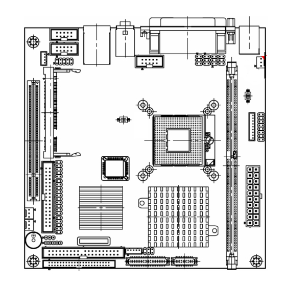
Page 88: Mechanical Drawing
AIMB-250 Series 5 Mechanical Drawing 88 AIMB-250 Series User’s Manual... - Page 89 User’s Manual Unit: mm AIMB-250 User’s Manual 89...
-
Page 90: Appendix A: Award Bios Post Messages
AIMB-250 Series Appendix A: AWARD BIOS POST Messages 90 AIMB-250 Series User’s Manual... -
Page 91: Overview
User’s Manual Overview During the Power On Self-Test (POST), if the BIOS detects an error requiring you to do something to fix, it will either sound a beep code or display a message. If a message is displayed, it will be accompanied by: PRESS F1 TO CONTINUE, CTRL-ALT-ESC OR DEL TO ENTER SETUP Post Beep Currently there are two kinds of beep codes in BIOS. -
Page 92: Display Switch Is Set Incorrectly
AIMB-250 Series DISPLAY SWITCH IS SET INCORRECTLY Display switch on the motherboard can be set to either monochrome or color. This indicates the switch is set to a different setting than indicated in Setup. Determine which setting is correct, and then either turn off the system and change the jumper, or enter Setup and change the VIDEO selection. -
Page 93: Invalid Eisa Configuration Please Run Eisa Configuration Utility
User’s Manual 12. Invalid EISA Configuration PLEASE RUN EISA CONFIGURATION UTILITY The non-volatile memory containing EISA configuration information was programmed incorrectly or has become corrupt. Re-run EISA configuration utility to correctly program the memory. Note: When either of these errors appears, the system will boot in ISA mode, which allows you to run the EISA Configuration Utility. -
Page 94: Press A Key To Reboot
AIMB-250 Series 20. PRESS A KEY TO REBOOT This will be displayed at the bottom screen when an error occurs that requires you to reboot. Press any key and the system will reboot. 21. PRESS F1 TO DISABLE NMI, F2 TO REBOOT When BIOS detects a Non-maskable Interrupt condition during boot, this will allow you to disable the NMI and continue to boot, or you can reboot the system with the NMI enabled. -
Page 95: Wrong Board In Slot Please Run Eisa Configuration Utility
User’s Manual 27. Wrong Board In Slot PLEASE RUN EISA CONFIGURATION UTILITY The board ID does not match the ID stored in the EISA non-volatile memory. Note: When either of these errors appears, the system will boot in ISA mode, which allows you to run the EISA Configuration Utility. -
Page 96: Post Codes
AIMB-250 Series 40. POST Codes Please take reference to Phoenix-Award website for the latest post codes. http://www.phoenix.com/en/Customer+Services/BIOS/AwardBIOS/Award+Error+Codes.ht 40.1 Normal POST Code EISA POST codes are typically output to port address 300h. ISA POST codes are output to Note: port address 80h. Code (hex) Name Description... - Page 97 User’s Manual Code (hex) Name Description Early Superio Init Early Initialized the super IO Reserved Blank video Reset Video controller Reserved Init KBC Keyboard controller init KB test Test the Keyboard Reserved Mouse Init Initialized the mouse Onboard Audio init Onboard audio controller initialize if exist Reserved Reserved...
- Page 98 AIMB-250 Series Code (hex) Name Description Reserved Reserved KBC final Init Final Initial KBC and setup BIOS data area Reserved Initialize Video Interface Read CMOS location 14h to find out type of video in use. Detect and Initialize Video Adapter. Reserved Reserved Reserved...
- Page 99 User’s Manual Code (hex) Name Description Test Stuck 8259's Turn off interrupts then verify no interrupt mask register is on. Interrupt Bits Test 8259 Interrupt Force an interrupt and verify the interrupt occurred. Functionality Reserved Reserved Reserved Set EISA Mode If EISA non-volatile memory checksum is good, execute EISA initialization.
- Page 100 AIMB-250 Series Code (hex) Name Description Reserved Reserved Setup enable Display setup message and enable setup functions Reserved Reserved Initialize & Install Detect if mouse is present, initialize mouse, install interrupt Mouse vectors. Reserved PS2 Mouse special Special treatment to PS2 Mouse port Reserved ACPI init ACPI sub-system initializing...
- Page 101 User’s Manual Code (hex) Name Description Reserved Reserved POST error check Check POST error and display them and ask for user intervention Reserved Reserved Security Check Ask password security (optional). Write CMOS Write all CMOS values back to RAM and clear screen. Pre-boot Enable Enable parity checker.
- Page 102 AIMB-250 Series 40.2 Quick POST Codes Code (hex) Name Description Init onboard device Early Initialized the super IO. Reset Video controller. Keyboard controller init Test the Keyboard Initialized the mouse Onboard audio controller initialize if exist. Check the intergraty of the ROM, BIOS and message Check Flash type and copy flash write/erase routines to 0F000h segments Check Cmos Circuitry and reset CMOS Program the chipset registers with CMOS values Init onboard...
- Page 103 User’s Manual Code (hex) Name Description Install FDD Enter setup check and auto11 configuration check up Initialize floppy disk drive controller and any drives. Install FDD and setup BIOS data area parameters Install FDD Initialize hard drive controller and any drives. IDE device detection and install Initialize any serial and parallel ports (also game port).
- Page 104 AIMB-250 Series 40.3 S4 POST Codes Code (hex) Name Description Early Chipset Init Early Initialized the super IO. Reset Video controller. Keyboard controller init. Test the Keyboard Initilized the mouse Cmos Check Check Cmos Circuitry and reset CMOS Chipset default Prog Program the chipset registers with CMOS values.
- Page 105 User’s Manual 40.4 BootBlock POST Codes Code (hex) Name Description Base memory test Clear base memory area (0000:0000--9000:ffffh) KB init Initialized KBC Install interrupt vectors Install int. vector (0-77), and initialized 00-1fh to their proper place Init Video Video initializing Init FDD Scan floppy and media capacity for onboard superIO Boot...
Need help?
Do you have a question about the Mini-ITX AIMB-250 Series and is the answer not in the manual?
Questions and answers