
Related Manuals for Advantech AIMB-286


Summary of Contents for Advantech AIMB-286
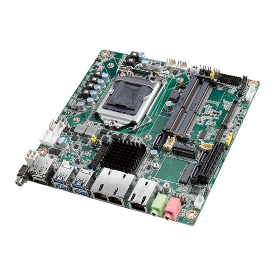
- Page 1 User Manual AIMB-286 Intel® Core™ i7/i5/i3/Pentium/ Celeron LGA1151 Mini-ITX with DP++/HDMI/LVDS (or eDP), 6 COM & 8 USB, 3 LAN, and PCIex4...
- Page 2 Because of Advantech’s high quality-control standards and rigorous testing, most of our customers never need to use our repair service. If an Advantech product is defec- tive, it will be repaired or replaced at no charge during the warranty period. For out- of-warranty repairs, you will be billed according to the cost of replacement materials, service time and freight.
- Page 3 Advantech has come to be known. Your satisfaction is our primary concern. Here is a guide to Advantech’s cus- tomer services.
- Page 4 Caution! There is a danger of a new battery exploding if it is incorrectly installed. Do not attempt to recharge, force open, or heat the battery. Replace the battery only with the same or equivalent type recommended by the man- ufacturer. Discard used batteries according to the manufacturer's instructions. AIMB-286 User Manual...
- Page 5 Ordering Information Chip- LVDS/ HDMI USB3. M.2 B M.2 E DP1.2 COM SATAIII PCIex4 TPM AMP 0/2.0 AIMB-286F- H310 1/ (1) 00A1E AIMB-286G2- H310 1/ (1) 00A1E AIMB-286L- H310 00A1E * ( ) is not populated when MP AIMB-286 User Manual...
- Page 6 It should be free of marks and scratches and in perfect working order upon receipt. As you unpack the AIMB-286, check it for signs of ship- ping damage. (For example, damaged box, scratches, dents, etc.) If it is damaged or it fails to meet the specifications, notify our service department or your local sales representative immediately.
-
Page 7: Table Of Contents
Figure 1.1 Jumper and Connector Location (Top Side)....5 Figure 1.2 Jumper and Connector Location (Bottom Side) ..6 AIMB-286 Board Diagram ................. 7 Figure 1.3 AIMB-286 Board Diagram .......... 7 Safety Precautions ..................7 Jumper Settings ..................8 1.8.1 How to Set Jumpers.............. - Page 8 Boot Setting ................90 3.2.6 Save & Exit Configuration............91 Chapter Software Introduction & Service ..93 Introduction ..................... 94 Value-Added Software Services ............. 94 4.2.1 Software API................94 4.2.2 Software Utility................96 Chapter Chipset Software Installation Utility AIMB-286 User Manual viii...
- Page 9 TI’s SMBUS Programming for +Vcore/+VCCGT Controller (JSMB1) ... 121 A.38 LGA1151 CPU Socket H4 (CPU1)............121 A.39 CPU FAN Power Connector (CPUFAN1) ..........122 A.40 LVDS Backlight Inverter Power Connector (INV1)........ 122 A.41 SATA Power Connector (SATA_PWR2)..........122 AIMB-286 User Manual...
- Page 10 SATA Power Connector (SATA_PWR1)..........123 A.43 eDP/LVDS Panel Connector (LVDS_EDP1)......... 123 A.44 ATX 12V Power Supply Connector (ATX12V1) ........124 A.45 SIM Card Connector (SIM1) ..............124 A.46 Buzzer (SP1)..................124 A.47 CPU Back Plate (CPU0_BACKPLATE1) ..........125 AIMB-286 User Manual...
-
Page 11: Chapter 1 General Information
Chapter General Information... -
Page 12: Introduction
Introduction AIMB-286 is designed with the Intel® H310 PCH for industrial applications that require both performance computing and enhanced power management capabilities. The motherboard supports Intel desktop Corei7/i5/i3/Pentium/Celeron processor up to 12 MB SmartCache and 2 DDR4 2666MHz SO-DIMM, up to 32 GB. A rich I/O con- nectivity of 6 x serial ports, 4 USB 3.0 + 4 USB 2.0, 3 GbE LAN, 3 SATA III, 1 NGFF... -
Page 13: Ethernet Lan
Board weight: 0.365 kg Jumpers and Connectors Connectors on the AIMB-286 motherboard link it to devices such as hard disk drives and a keyboard. In addition, the board has a number of jumpers used to configure your system for your application. - Page 14 LGA1151 CPU Socket H4 CPU1 CPU FAN Power Connector CPUFAN1 eDP/LVDS Backlight Inverter Power Connector INV1 SATA_PWR1/ SATA Power Connector SATA_PWR2 eDP/LVDS Panel Connector LVDS_EDP1 ATX 12V Power Supply Connector ATX12V1 SIM Card Connector SIM1 Buzzer CPU Back Plate CPU0_BACKPLATE1 AIMB-286 User Manual...
-
Page 15: Board Layout: Jumper And Connector Locations
LVDS_EDP1 SATA1 SATA_PWR2 SATA_PWR1 SATA3 CPUFAN1 INV1 PCIEX4_1 SATA2 USB56 USB78 JWDT1+ JOBS1 JLVDS1 GPIO1 SPI1 COM3456 SPI_CN1 KBMS1 LPC1 SYSFAN2 JSETCOM1_V1 SYSFAN1 COM12 PSON1 JFP1 JCASE1 JCASEOP_SW1 JFP2 Figure 1.1 Jumper and Connector Location (Top Side) AIMB-286 User Manual... - Page 16 SIM1 Figure 1.2 Jumper and Connector Location (Bottom Side) AIMB-286 User Manual...
-
Page 17: Aimb-286 Board Diagram
3 x RS-232, 1 x RS-232/422/485 (RS-422/485 support by BOM optional) PS/2, WDT, 16-bit GPIO Figure 1.3 AIMB-286 Board Diagram Safety Precautions Warning! Always completely disconnect the power cord from chassis whenever you work with the hardware. Do not make connections while the power is on. -
Page 18: Jumper Settings
1.8.2 CMOS Clear (JCMOS1) The AIMB-286 motherboard contains a jumper that can erase CMOS data and reset the system BIOS information. Normally this jumper should be set with pins 1-2 closed. If you want to reset the CMOS data, set CMOS1 to 2-3 closed for just a few seconds, and then move the jumper back to 1-2 closed. -
Page 19: Power Switch/Hdd Led/Smbus/Speaker Pin Header (Jfp1)
Watchdog Timer Output and OBS Beep (JWDT1+JOBS1) Table 1.6: Watchdog Timer Output and OBS Beep (JWDT1+JOBS1) Function Jumper Setting Watchdog Timer Output(2-3) (Default) OBS BEEP(4-5) (Default) (2 and 3)+(4 and 5) Watchdog Timer Disable (1-2) OBS BEEP(4-5) (Default) (1 and 2)+(4 and 5) AIMB-286 User Manual... -
Page 20: Atx/At Mode Selection (Pson1)
2-3 closed 1.8.7 LVDS/eDP Panel Voltage Selection (JLVDS1) Table 1.8: LVDS/eDP Panel Voltage Selection (JLVDS1) Function Jumper Setting Jumper position for 5V JLVDS1 (2-4) Jumper position for 3.3V (Default) JLVDS1 (4-6) Jumper position for 12V JLVDS1 (3-4) AIMB-286 User Manual... -
Page 21: Com1 Ri# Pin Ri#/5V/12V Select (Jsetcom1_V1)
Function Jumper Setting Normal Open Normal Close (Default) 1.8.10 JLVDS_VCON1: LVDS VESA, JEIDA format selection pin header Table 1.11: JLVDS_VCON1: LVDS VESA, JEIDA format selection pin header Function Jumper Setting JEIDA mode (HI=+3.3V) VESA mode (Low=0V) (Default) AIMB-286 User Manual... -
Page 22: System Memory
System Memory AIMB-286 has two sockets for a 260 pins DDR4 SO-DIMM. This socket uses a 1.2 V unbuffered double data rate synchronous DRAM (DDR SDRAM). DRAM is available in capacities of 4GB, 8GB and 16GB. The sockets can be filled in any combination with SODIMMs of any size, giving a total memory size between 4GB, 8GB, 16GB, and up to max 32GB. -
Page 23: Chapter 2 Connecting Peripherals
Chapter Connecting Peripherals... -
Page 24: Introduction
LAN + USB Ports (LAN1/2/3, USB12, USB34) The AIMB-286 provides up to 8 USB ports. There are 4 x USB 3.0 on the rear side and 4 x USB 2.0 pin header on the board. The USB interface complies with the USB specification revision 2.0 that supports transmission rates of up to 480 Mbps, revision... -
Page 25: Dp + Hdmi Connector (Dp1 + Hdmi1)
COM3456 COM3456 COM1/2 AIMB-286 supports six serial ports, COM1/4/5/6 support RS-232 function, COM2/3 support RS-232/422/485 function (RS422/485 support by BOM optional). These ports can connect to serial devices, such as a mouse or a printer, or to a communica- tions network. The IRQ and address ranges for these ports are fixed. However, if you want to disable the port or change these parameters later, you can do this in the sys- tem BIOS setup. -
Page 26: Ps/2 Keyboard And Mouse Connector (Kbms1)
PS/2 Keyboard and Mouse Connector (KBMS1) On board 6-pin wafer box connector, supports one standard PS/2 keyboard, one standard PS/2 mouse. CPU Fan Connector (CPU_FAN1) If a fan is used, this connector supports cooling fans of 500 mA (6 W) or less. AIMB-286 User Manual... -
Page 27: System Fan Connector (Sysfan1/2)
If a fan is used, this connector supports cooling fans of 500 mA (6 W) or less. Power Switch/HDD LED/SMBUS/Speaker Pin Header (JFP1) & Power LED and Keyboard Lock Pin Header (JFP2) There are several headers for monitoring and controlling the AIMB-286. JFP1 JFP2 2.8.1... -
Page 28: Reset (Jfp1/Reset)
2.8.4 External speaker (JFP1/SPEAKER) JFP1/SPEAKER is a 4-pin connector for an external speaker. If there is no external speaker, the AIMB-286 provides an onboard buzzer as an alternative. To enable the buzzer, set pins 7 & 10 as closed. 2.8.5 Power LED and keyboard lock connector (JFP2/PWR_LED &... -
Page 29: Atx 12V Power Supply Connector (Atx12V1) & Atx Power Supply Connector (Atx_5Vsb1)
ATX Power Supply Connector (ATX_5VSB1) ATX12V1 ATX_5VSB1 2.10 SATA Signal Connector (SATA1/2/3) SATA1 SATA3 SATA2 AIMB-286 features a high performance Serial ATA III interface (up to 600 MB/s) which eases hard drive cabling with thin, space-saving cables. AIMB-286 User Manual... -
Page 30: Hd Analog Audio Interface (Audio1/2, Fpaud1)
2.11 HD Analog Audio Interface (AUDIO1/2, FPAUD1) AUDIO1/2 FPAUD1 2.12 PCI-E X4 Slot (PCIEX4_1) AIMB-286 User Manual... -
Page 31: Edp/Lvds Panel Connector (Lvds_Edp1)
Pin 3: GND -> Panel connected NC/3.3V -> No panel 2.14 LVDS/eDP Backlight Inverter Power Connector (INV1) Note! Signal Description Signal Signal Description Vadj=0.75 V (Recommended: 4.7 K, 1/16 W) ENBKL LCD backlight ON/OFF control signal) AIMB-286 User Manual... -
Page 32: Ngff M.2 E-Key Connector For 2230 Module (M2E1)
2.15 NGFF M.2 E-Key connector for 2230 module (M2E1) 2.16 NGFF M.2 B-Key connector for 2242/3042 module (M2B1) AIMB-286 User Manual... -
Page 33: Hd Digital Audio Interface (Spdif1)
2.17 HD Digital Audio Interface (SPDIF1) 2.18 Audio Amplifier Output Connector (AMP1) AIMB-286 User Manual... -
Page 34: General Purpose I/O Pin Header (Gpio1)
2.19 General Purpose I/O Pin Header (GPIO1) 2.20 SPI BIOS Flash Socket (SPI1) AIMB-286 User Manual... -
Page 35: Spi Programming Pin Header (Spi_Cn1)
2.21 SPI Programming Pin Header (SPI_CN1) 2.22 Low Pin Count Header (LPC1) AIMB-286 User Manual... -
Page 36: Case-Open Detect Connector (Jcase1)
2.23 Case-Open Detect Connector (JCASE1) The SPI flash card pin header may be used to flash BIOS if the AIMB-286 cannot power on. 2.24 Battery Wafer Box (BAT1) AIMB-286 User Manual... -
Page 37: Cpu Socket (Cpu1)
2.25 CPU Socket (CPU1) 2.26 DDR4 SO-DIMM Socket (DIMMA1, DIMMB1) AIMB-286 User Manual... -
Page 38: Sata Power Connector (Sata_Pwr1/2)
2.27 SATA Power Connector (SATA_PWR1/2) 2.28 DC Input Connector (DCIN1) AIMB-286 User Manual... -
Page 39: Bios Operation
Chapter BIOS Operation... -
Page 40: Introduction
AIMB-286 setup screens. BIOS Setup The AIMB-286 Series system has AMI BIOS built in, with a CMOS SETUP utility that allows users to configure required settings or to activate certain system features. The CMOS SETUP saves the configuration in the CMOS RAM of the motherboard. When the power is turned off, the battery on the board supplies the necessary power to pre- serve the CMOS RAM. -
Page 41: Main Menu
System Date using the <Arrow> keys. Enter new values via the keyboard. Press the <Tab> or <Arrow> keys to move between fields. The date must be entered in MM/DD/YY format. The time must be entered in HH:MM:SS format. AIMB-286 User Manual... -
Page 42: Advanced Bios Features
3.2.2 Advanced BIOS Features Select the Advanced tab from the AIMB-286 Setup menu to enter the Advanced BIOS Setup page. Users can select any item in the left frame of the screen, such as CPU Configuration, to access the submenu for that item. Select an Advanced BIOS Setup option by highlighting the text using the <Arrow>... - Page 43 3.2.2.1 Platform Misc Configuration Native PCIE Enable [ Enable ] Native ASPM [ Auto ] AIMB-286 User Manual...
- Page 44 3.2.2.2 CPU Configuration CPU Flex Ratio Override [Disabled] Intel (VMX) Virtualization [Enabled] PECI [Enabled] Active Processor Cores [All] BIST [Disabled] AES [Enabled] AIMB-286 User Manual...
- Page 45 CPU SMM Enhancement SMM Use Delay Indication [Enabled] SMM Use Block Indication [Enabled] AIMB-286 User Manual...
- Page 46 3.2.2.3 Power & Performance AIMB-286 User Manual...
- Page 47 C-state Auto Demotion [C1 and C3] C-state Un- demotion [C1 and C3] Package C-state Un-demotion [Disabled] Package C-state Demotion [Disabled] CState Pre-Wake [Enabled] IO MWAIT Redirection [Disabled] Package C-state Limit [C7] Time Unit [1024 ns] AIMB-286 User Manual...
- Page 48 CPU VR Settings Intersil VR Command [Disabled] Acoustic Noise Settings Acoustic Noise Mitigation [Disabled] AIMB-286 User Manual...
- Page 49 Slow Slew Rate for GT Domain [Fast/2] Disable Fast PKG C State Ramp for SA Domain [FALSE] Slow Slew Rate for SA Domain [Fast/2] Disable Fast PKG C State Ramp for VccIn Domain [FALSE] Core/IA VR Settings AIMB-286 User Manual...
- Page 50 VR Config Enable [ Enabled ] PS3 Enable [Enabled] PS4 Enable [Enabled] TDC Enable [Enabled] TDC Time Window [1 ms] TDC Lock [Disabled] AIMB-286 User Manual...
- Page 51 CPU VR Settings VR Config Enable [ Enabled ] PS3 Enable [Enabled] PS4 Enable [Enabled] TDC Enable [Enabled] TDC Time Window [1 ms] AIMB-286 User Manual...
- Page 52 TDC Lock [Disabled] Custom P-state Table AIMB-286 User Manual...
- Page 53 Power Limit 3 Override [Disabled] AIMB-286 User Manual...
- Page 54 3.2.2.4 PCH-FW Configuration Me FW Image Re-Flash [Disabled] Local FW Update [Enabled] AIMB-286 User Manual...
- Page 55 3.2.2.5 Power & Performance RC6 (Render Standby) [Enabled] Maximum GT frequency [Default Max Frequency] Disable Turbo GT frequency [Disabled] AIMB-286 User Manual...
- Page 56 ME State [Enabled] 3.2.2.6 Trusted Computing AIMB-286 User Manual...
- Page 57 SHA256 PCR Bank [Enabled] Pending operation [None] Platform Hierarchy [Enabled] Storage Hierarchy [Enabled] Endorsement Hierarchy [Enabled] TPM2.0 UEFI Spec Version [TCG_2] Physical Presence Spec Version [1.3] TPM 20 Interface Type [TIS] AIMB-286 User Manual...
- Page 58 3.2.2.7 ACPI Settings Enable ACPI Auto Configuration [ Disabled ] Enable Hibernation [Enabled] ACPI Sleep State [S3 (Suspend to RAM)] Lock Legacy Resource [Disabled] S3 Video Repost [Disabled] AIMB-286 User Manual...
- Page 59 3.2.2.8 NCT6776 Super IO Configuration Super IO Chip NCT6776 Case Open Warning [Disabled] Wake On Ring [Disabled] Watch Dog Timer [Disabled] AIMB-286 User Manual...
- Page 60 Serial Port 1 Configuration Serial Port [ Enabled ] – Device Settings: IO=3F8h; IRQ =4 – Change Settings [ Auto ] To select an optimal setting for serial port 1. Serial Port 2 Configuration AIMB-286 User Manual...
- Page 61 Change Settings [ Auto ] To select an optimal setting for serial port 2. RS485 Auto Flow Control Function [ Disabled ] Digital I/O Configuration Digital I/O Pin 1 - 16 [ Input ] AIMB-286 User Manual...
- Page 62 ACPI Shutdown Temperature [ Disabled ] Use this to set the ACPI shutdown temperature threshold. When the system reaches the shutdown temperature, it will be automatically shut down by ACPI OS to protect the system from overheating damage. AIMB-286 User Manual...
- Page 63 CPU FAN Mode [ SMART FAN IV Mode ] The item shows you CPU temperature and fan speed (PWM) information. SYSFAN Mode [ SMART FAN IV Mode ] The item shows you system temperature and fan speed (PWM) information. AIMB-286 User Manual...
- Page 64 3.2.2.10 NCT5114DSEC Super IO Configuration AIMB-286 User Manual...
- Page 65 Serial Port 3 Configuration Serial Port [ Enabled ] Device Settings: IO=240h; IRQ =5 Change Setting [ Auto ] To select an optimal setting for serial port 3. RS-485 Auto Flow Control Function [ Disabled ] AIMB-286 User Manual...
- Page 66 Serial Port 4 Configuration Serial Port [ Enabled ] Device Settings: IO=248h; IRQ =5 Change Setting [ Auto ] To select an optimal setting for serial port 4. AIMB-286 User Manual...
- Page 67 Serial Port 5 Configuration Serial Port [ Enabled ] Device Settings: IO=250h; IRQ =5 Change Setting [ Auto ] To select an optimal setting for serial port 5. AIMB-286 User Manual...
- Page 68 Device Settings: IO=258h; IRQ =5 Change Setting [ Auto ] To select an optimal setting for serial port 6. 3.2.2.11 S5 RTC Wake Settings The item allows you enable or disable system wake up on alarm event. AIMB-286 User Manual...
- Page 69 Wake system from S5 [ Disabled ] 3.2.2.12 Serial Port Console Redirection AIMB-286 User Manual...
- Page 70 Console Redirection [ Disabled ] Redirection COM Port [COM1] Resolution [80x24] Redirect After POST [Always Enable] AIMB-286 User Manual...
- Page 71 3.2.2.13 Intel TXT Information AIMB-286 User Manual...
- Page 72 Legacy USB Support [ Enabled ] XHCI Hand-off [ Enabled ] USB Mass Storage Driver Support [ Enabled ] USB transfer time-out [ 20 sec ] Device reset time-out [ 20 sec ] AIMB-286 User Manual...
- Page 73 Device power-up delay [ Auto ] JetFlashTranscend 32GB 1100 [ Auto ] 3.2.2.15 Network Stack Configuration Network Stack [Disabled] AIMB-286 User Manual...
- Page 74 3.2.2.16 CSM Configuration CSM Support [ Enabled ] GateA20 Active [ Upon request ] INT19 Trap Response [Immediate ] Boot option filter [ UEFI only ] Network [UEFI] AIMB-286 User Manual...
-
Page 75: Chipset Configuration Setting
Users can display a Chipset Setup option by highlighting it using the <Arrow> keys. All Chipset Setup options are described in this section. The Chipset Setup screens are shown below. The sub menus are described on the following pages. AIMB-286 User Manual... - Page 76 3.2.3.1 System Agent (SA) Configuration VT-d [ Enabled ] Above 4GB MMIO BIOS assignment [ Disabled ] Memory Configuration AIMB-286 User Manual...
- Page 77 Maximum Memory Frequency (Auto) Max TOLUD (Dynamic) Maximum Value of TOLUD. Dynamic assignment would adjust TOLUD auto- matically based on largest MMIO length of installed graphic controller. Fast Boot [Enabled] Enable or disable Fast Boot support. AIMB-286 User Manual...
- Page 78 Select DVMT 5.0 Pre-Allocated (Fixed) Graphics Memory size used by the Internal Graphics Device. DVMT Total Gfx Mem [ 256M ] Select DVMT5.0 Total Graphic Memory size used by the Internal Graphics Device. PM Support [ Enabled ] PAVP [ Enabled ] AIMB-286 User Manual...
- Page 79 LCD Control LVDS Panel Type [ Disabled ] eDP/LVDS Backlight Signal Control [ LINEAR ] AIMB-286 User Manual...
- Page 80 DMI/OPI Configuration DMI Max Link Speed [Auto] DMI Gen3 Eq Phase 2 [Auto] DMI Gen3 Eq Phase 3 Method [Auto] Program Static Phase1 Eq [Enabled] DMI Link ASPM Control [L0Sl1] AIMB-286 User Manual...
- Page 81 DMI Extended Sync Control [Disabled] DMI De-emphasis Control [-3.5 dB] DMI IOT [Disabled] AIMB-286 User Manual...
- Page 82 AIMB-286 User Manual...
- Page 83 PEG Port Configuration AIMB-286 User Manual...
- Page 84 Disabled: PCIe ASPM will be programmed before OpROM. Program Static Phase1 Eq [Enabled] Always Attempt SW EQ [Disabled] Number of Presets to test [Auto] Allow PERST# GPIO Usage [Enabled] SW EQ Enable VOC [Auto] AIMB-286 User Manual...
- Page 85 Detect Non-Compliance Device [Disabled] AIMB-286 User Manual...
- Page 86 Gen3 Root Port Preset Value for each Lane Root Port Preset Value Per lane for Gen3 Equalization. AIMB-286 User Manual...
- Page 87 Gen3 Endpoint Preset Value each Lane Endpoint Preset Value Per lane for Gen3 Equalization. AIMB-286 User Manual...
- Page 88 Gen3 Endpoint Hint Value each Lane Endpoint Hint Value Per lane for Gen3 Equalization. AIMB-286 User Manual...
- Page 89 PEG10 RxCTLE Override [ Disabled ] PEG11 RxCTLE Override [ Disabled ] PEG12 RxCTLE Override [ Disabled ] DMI RxCTLE Override [ Disabled ] AIMB-286 User Manual...
- Page 90 3.2.3.2 PCH-IO Configuration PCI Express Configuration PCI Express Configuration SATA And RST Configuration Security Configuration AIMB-286 User Manual...
- Page 91 PCI Express Clock Gating [ Enabled ] Enable or Disable PCI Express clock gating for each port. DMI Link ASPM Control [ L0sL1 ] PCIe-USB Glitch W/A [ Disabled ] PCIe-USB Glitch W/A for bad USB device(s) connected behind PCIE/PEG Port. AIMB-286 User Manual...
- Page 92 Override SW EQ Settings [ Disabled ] AIMB-286 User Manual...
- Page 93 M.2 E-Key slot [ Enabled ] Control the M.2 E-Key Root Port. ASPM 4 [ Disabled ] Set the ASPM Level: Force L0s - Force all links to L0s State : AUTO - BIOS auto configure : DISABLE - Disables ASPM AIMB-286 User Manual...
- Page 94 Set the ASPM Level: Force L0s - Force all links to L0s State : AUTO - BIOS auto configure : DISABLE - Disables ASPM L1 Substates [ Disabled ] Hot Plug [ Disabled ] Advanced Errors Reporting [ Disabled ] PCIE Speed [Auto ] AIMB-286 User Manual...
- Page 95 SATA and RST Configuration SATA Controller(s) [ Enabled ] SATA Mode Selection [ AHCI ] Aggressive LPM Support [ Enabled ] SATA Controller Speed [ Default ] AIMB-286 User Manual...
- Page 96 Serial ATA Port 1 (SATA) Port 1 [Enabled ] Spin Up Device [ Disabled ] SATA Device Type [ Hard Disk Drive ] SATA Port 1 DevS1p [ Disabled] DIT0 Configuration [ Disabled ] Security Configuration AIMB-286 User Manual...
- Page 97 RTC Memory Lock [ Enabled] BIOS Lock [ Enabled] HD Audio Configuration AIMB-286 User Manual...
- Page 98 HD Audio [ Enabled] AIMB-286 User Manual...
-
Page 99: Security
Select this option and press <ENTER> to access the sub menu, and then type in the password. Set the Administrator password. User Password Select this option and press <ENTER> to access the sub menu, and then type in the password. Set the User Password. AIMB-286 User Manual... -
Page 100: Boot Setting
On or Off power on state for the NumLock Quiet Boot [ Disabled ] If this option is set to disabled, the BIOS displays normal POST messages. If enabled, an OEM logo is shown instead of POST messages. AIMB-286 User Manual... -
Page 101: Save & Exit Configuration
BIOS setup menu and reboot the computer to take effect all sys- tem configuration parameters. 1. Select Save Changes and Reset from the Save & Exit menu and press <Enter>. The following message appears: Save Configuration Changes and Exit Now? [Ok] or [Cancel] 2. Select [Ok] or [Cancel] AIMB-286 User Manual... - Page 102 <Enter>. Save as User Default Save the all current settings as a user default. Restore User Default Restore all settings to user default values. Boot Override Shows the boot device types on the system. AIMB-286 User Manual...
-
Page 103: Software Introduction & Service
Chapter Software Introduction & Service... -
Page 104: Introduction
Introduction The mission of Advantech Embedded Software Services is to "Enhance quality of life with Advantech platforms and Microsoft® Windows® embedded technology." We enable Windows® Embedded software products on Advantech platforms to more effectively support the embedded computing community. Customers are freed from the hassle of dealing with multiple vendors (hardware suppliers, system integrators, embedded OS distributors) for projects. - Page 105 System Throttling Refers to a series of methods for reducing power consump- tion in computers by lowering the clock frequency. This API allows the user to adjust the clock from 87.5% to 12.5%. AIMB-286 User Manual...
-
Page 106: Software Utility
The Monitoring is a utility for customer to monitor the sys- tem health, like voltage, CPU and system temperature and fan speed. These items are important to a device, if the critical errors occur and are not solved immediately, per- manent damage may be caused. AIMB-286 User Manual... -
Page 107: Chipset Software Installation Utility
Chapter Chipset Software Installation Utility... -
Page 108: Before You Begin
Before You Begin To facilitate the installation of the enhanced display drivers and utility software, read the instructions in this chapter carefully. The drivers for the AIMB-286 are located on Advantech support website: http://support.advantech.com/Support/. The driver on the support website will guide and link you to the utilities and drivers under a Win- dows system. -
Page 109: Vga Setup
Chapter VGA Setup... -
Page 110: Introduction
See Chapter 5 for information on installing the CSI util- ity. Download the driver from website on your computer. Navigate to the "AIMB- 286_Graphic_Win10(64bit)" folder and click "setup.exe" to complete the installation of the drivers for Windows 10. AIMB-286 User Manual... -
Page 111: Lan Configuration
Chapter LAN Configuration... -
Page 112: Introduction
Introduction The AIMB-286 has three Gigabit Ethernet LANs via dedicated PCI Express x1 lanes (Realtek 8111G (LAN1/2) and Intel i211AT (LAN3)) that offer bandwidth of up to 500 MB/sec, eliminating the bottleneck of network data flow and incorporating Gigabit Ethernet at 1000 Mbps. -
Page 113: Appendix A I/O Pin Assignments
Appendix I/O Pin Assignments... -
Page 114: Dc Input Phoenix Connector (Dcin1)
Power input (Only +12V) Definition Multimedia Interface (DP1+HDMI1) Signal Pin Definition Signal Pin Definition HDMI1_Z_D2+ DP1_0+ HDMI1_Z_D2- DP1_0- HDMI1_Z_D1+ DP1_1+ HDMI1_Z_D1- DP1_1- HDMI1_Z_D0+ DP1_2+ HDMI1_Z_D0- DP1_2- HDMI1_Z_CLK+ DP1_3+ HDMI1_Z_CLK- DP1_3- DP1_AUX_EN# HDMI1_SCL DP1_AUX+ HDMI1_SDA DP1_AUX- +V5_HDMI DP1_HPD HDMI1_HPD +V3.3_DP1 AIMB-286 User Manual... -
Page 115: Atx Power Supply (5Vsb) Connector (Atx_5Vsb1)
ATX Power supply (5VSB) connector (ATX_5VSB1) Signal Pin Definition +V5SB PS_ON# USB 3.0 Stack Connector (USB12) Signal Pin Definition Signal Pin Definition USB_D1- USB_D2- USB_D1+ USB_D2+ USB31X1_z_RX- USB31X2_z_RX- USB31X1_z_RX+ USB31X2_z_RX+ USB31X1_z_TX- USB31X2_z_TX- AIMB-286 User Manual... -
Page 116: Usb 3.0 Stack Connector (Usb34)
RJ45 2 Port (LAN12) Signal Pin Definition Signal Pin Definition LAN1_MDI0+ LAN2_MDI0+ LAN1_MDI0- LAN2_MDI0- LAN1_MDI1+ LAN2_MDI1+ LAN1_MDI1- LAN2_MDI1- LAN1_CONN LAN2_CONN LAN1_CT LAN2_CT LAN1_MDI2+ LAN2_MDI2+ LAN1_MDI2- LAN2_MDI2- LAN1_MDI3+ LAN2_MDI3+ LAN1_MDI3- LAN2_MDI3- LAN1_LED0_ACT#_R LAN2_LED0_ACT#_R +V3.3_DUAL +V3.3_DUAL LAN1_LED1_1G#_R LAN2_LED1_1G#_R LAN1_LED2_100M#_R LAN2_LED2_100M#_R AIMB-286 User Manual... -
Page 117: Platform Controller Hub (Pch1)
Platform Controller Hub (PCH1) RJ45 1 Port (LAN1) Signal Pin Definition LAN1_MDI0+ LAN1_MDI0- LAN1_MDI1+ LAN1_MDI1- LAN1_CONN LAN1_CT LAN1_MDI2+ LAN1_MDI2- LAN1_MDI3+ LAN1_MDI3- LAN1_LED0_ACT#_R +V3.3_DUAL LAN1_LED1_1G#_R LAN1_LED2_100M#_R AIMB-286 User Manual... -
Page 118: Sata Signal Connector (Sata2)
SATA Signal Connector (SATA2) Signal Pin Definition A.10 RJ45 1 Port (LAN3) Signal Pin Definition LAN3_MDI0+ LAN3_MDI0- LAN3_MDI1+ LAN3_MDI1- LAN3_CONN LAN3_CT LAN3_MDI2+ LAN3_MDI2- LAN3_MDI3+ LAN3_MDI3- LAN3_LED0_ACT#_R +V3.3_LAN3_R LAN3_LED1_1G#_R LAN3_LED2_100M#_R AIMB-286 User Manual... -
Page 119: Battery Wafer Box (Bat1)
A.11 Battery Wafer Box (BAT1) Signal Pin Definition VBAT A.12 HD Analog Audio Interface (AUDIO1) Signal Pin Definition LINE-OUT A.13 HD Analog Audio Interface (AUDIO2) Signal Pin Definition AIMB-286 User Manual... -
Page 120: Front Hd Analog Audio Interface (Fpaud1)
MIC IN L MIC IN R FPAUD_DETECT# LINE OUT R SENSE R1 SENSE LINE OUT L SENSE R2 A.15 Audio Amplifier Output Connector (AMP1) Signal Pin Definition A.16 HD Digital Audio Interface (SPDIF1) Signal Pin Definition SPDIF OUT AIMB-286 User Manual... -
Page 121: Sata Signal Connector (Sata1)
Signal Pin Definition Signal Pin Definition +12V PRSNT1# +12V +12V +12V +12V SMB_CLK Reserved SMB_DATA Reserved Reserved +3.3V Reserved Reserved +3.3V +3.3VAUX +3.3V WAKE# PWRGD Reserved REFCLK+ TX0+ REFCLK- TX0- RX0+ Reserved RX0- DETECT# TX1+ CONFIG1 TX1- AIMB-286 User Manual... -
Page 122: Ngff M.2 E-Key Connector For 2230 Module (M2E1)
LED2# (I)(OD) CNV_WR_z_D0+ UART WAKE# (I)(0/3.3V) CNV_WR_z_CLK- UART RXD (I)(0/1.8V) CNV_WR_z_CLK+ Connector KEY Connector KEY Connector KEY Connector KEY Connector KEY Connector KEY Connector KEY Connector KEY CNV_RGI_DT CNV_RGI_RSP PETp0 CNV_BRI_DT PETn0 PCH_CLINK_RST# PCH_CLINK_DATA PERp0 PCH_CLINK_CLK PERn0 CNV_GNSS_BLANKING AIMB-286 User Manual... -
Page 123: Sata Signal Connector (Sata3)
CNV_MFUART2_TXD REFCLKp0 CNV_MFUART2_RXD REFCLKn0 SUSCLK(32kHz) (O)(0/3.3V) PERST0# (O)(0/3.3V) CLKREQ0# W_DISABLE2# (O)(0/3.3V) PEWAKE0# W_DISABLE1# (O)(0/3.3V) RESERVED RESERVED/PETp1 RESERVED RESERVED/PETn1 RESERVED M.2_38P4M_REFCLK RESERVED/PERp1 RESERVED RESERVED/PERn1 RESERVED PCIE_WAKE# RESERVED/REFCLKp1 +3.3V RESERVED/REFCLKn1 +3.3V A.20 SATA Signal Connector (SATA3) Signal Pin Definition AIMB-286 User Manual... -
Page 124: Ngff M.2 B-Key Connector For 2242/3042 Module (M2B1)
Connector KEY Connector KEY Connector KEY CONFIG_0 PCIE_WAKE# M.2_GNSS_DISABLE# PERn1/USB3.0-Rx-/SSIC-RxN UIM-RESET (I) PERp1/USB3.0-Rx+/SSIC-RxP UIM-CLK (I) UIM-DATA (I/O) PETn1/USB3.0-Tx-/SSIC-TxN UIM-PWR (I) PETp1/USB3.0-Tx+/SSIC-TxP SATA_DEVSLP (O) M.2_ISH_SCL PERn0/SATA-B+ M.2_ISH_SDA PERp0/SATA-B- PETn0/SATA-A- PETp0/SATA-A+ PERST# CLKREQ# REFCLKn PEWAKE# REFCLKp RESET# SUSCLK(32kHz) CONFIG_1 +3.3V AIMB-286 User Manual... -
Page 125: Usb 2.0 Pin Header (Usb56)
+3.3V +3.3V CONFIG_2 A.22 USB 2.0 Pin Header (USB56) Signal Pin Definition Signal Pin Definition USB_D5- USB_D6- USB_D5+ USB_D6+ A.23 USB 2.0 Pin Header (USB78) Signal Pin Definition Signal Pin Definition USB_D7- USB_D8- USB_D7+ USB_D8+ AIMB-286 User Manual... -
Page 126: General Purpose I/O Pin Header (Gpio1)
General Purpose I/O Pin Header (GPIO1) Signal Pin Definition Signal Pin Definition GPIO0 GPIO8 GPIO1 GPIO9 GPIO2 GPIO10 GPIO3 GPIO11 GPIO4 GPIO12 GPIO5 GPIO13 GPIO6 GPIO14 GPIO7 GPIO15 +5VSB +5VSB A.25 DDR4 SO-DIMM Socket (DIMMA1) Please see JEDEC STANDARD Pin Definition AIMB-286 User Manual... -
Page 127: Ddr4 So-Dimm Socket (Dimmb1)
RI# [3] DCD# [4] DSR# [4] RXD [4] RST# [4] TXD [4] CTS# [4] DTR# [4] RI# [4] DCD# [5] DSR# [5] RXD [5] RST# [5] TXD [5] CTS# [5] DTR# [5] RI# [5] DCD# [6] DSR# [6] AIMB-286 User Manual... -
Page 128: Ps/2 Keyboard And Mouse Connector (Kbms1)
PS/2 Keyboard and Mouse Connector (KBMS1) Signal Pin Definition KB CLK KB DATA MS CLK MS DATA A.29 Low Pin Count Header (LPC1) Signal Pin Definition Signal Pin Definition CLK (24MHz) RESET# FRAME# +3.3V SMB_CLK SERIRQ SMB_DATA +5VSB AIMB-286 User Manual... -
Page 129: Com 2 Port (Com12)
RXD [2] RST# [2] TXD [2] CTS# [2] DTR# [2] RI# [2] A.31 Power LED and Keyboard Lock Pin Header (JFP2) Signal Pin Definition LED Power Keyboard LOCK# A.32 Case-Open Detect Connector (JCASE1) Signal Pin Definition Case Open AIMB-286 User Manual... -
Page 130: Spi Programming Pin Header (Spi_Cn1)
SPI BIOS Flash Socket (SPI1) Signal Pin Definition Signal Pin Definition MOSI MISO WP# / IO2 HOLD# / IO3 +3.3V A.35 SYSTEM FAN Power Connector (SYSFAN1) Signal Pin Definition SYSTEM FAN VCC SYSTEM FAN SPEED SYSTEM FAN PWM AIMB-286 User Manual... -
Page 131: System Fan Power Connector (Sysfan2)
A.36 SYSTEM FAN Power Connector (SYSFAN2) Signal Pin Definition SYSTEM FAN VCC SYSTEM FAN SPEED SYSTEM FAN PWM A.37 TI’s SMBUS Programming for +Vcore/+VCCGT Controller (JSMB1) Signal Pin Definition TPS53655_SMB_CLK TPS53655_SMB_DIO A.38 LGA1151 CPU Socket H4 (CPU1) AIMB-286 User Manual... -
Page 132: Cpu Fan Power Connector (Cpufan1)
CPU FAN Power Connector (CPUFAN1) Signal Pin Definition CPU FAN VCC CPU FAN SPEED CPU FAN PWM A.40 LVDS Backlight Inverter Power Connector (INV1) Signal Pin Definition +12V BKL_EN BKL_CTRL A.41 SATA Power Connector (SATA_PWR2) Signal Pin Definition +V12 AIMB-286 User Manual... -
Page 133: Sata Power Connector (Sata_Pwr1)
A.42 SATA Power Connector (SATA_PWR1) Signal Pin Definition +V12 A.43 eDP/LVDS Panel Connector (LVDS_EDP1) Signal Pin Definition Signal Pin Definition LVDS_DET# A0N(EDP_CPU_TXN2) A0P(EDP_CPU_TXP2) CLK1N(EDP_CPU_TXN3) CLK2N CLK1P(EDP_CPU_TXP3) CLK2P GND(EDP_CH7511_HPD) ENBKL VCON AIMB-286 User Manual... -
Page 134: Atx 12V Power Supply Connector (Atx12V1)
A.44 ATX 12V Power Supply Connector (ATX12V1) Signal Pin Definition +12V +12V A.45 SIM Card Connector (SIM1) Signal Pin Definition UIM_PWR UIM_RESET UIM_CLK UIM_VPP UIM_DATA A.46 Buzzer (SP1) AIMB-286 User Manual... -
Page 135: Cpu Back Plate (Cpu0_Backplate1)
A.47 CPU Back Plate (CPU0_BACKPLATE1) AIMB-286 User Manual... - Page 136 No part of this publication may be reproduced in any form or by any means, electronic, photocopying, recording or otherwise, without prior written permis- sion of the publisher. All brand and product names are trademarks or registered trademarks of their respective companies. © Advantech Co., Ltd. 2019...
Need help?
Do you have a question about the AIMB-286 and is the answer not in the manual?
Questions and answers