
Related Manuals for Advantech AIMB-287


Summary of Contents for Advantech AIMB-287
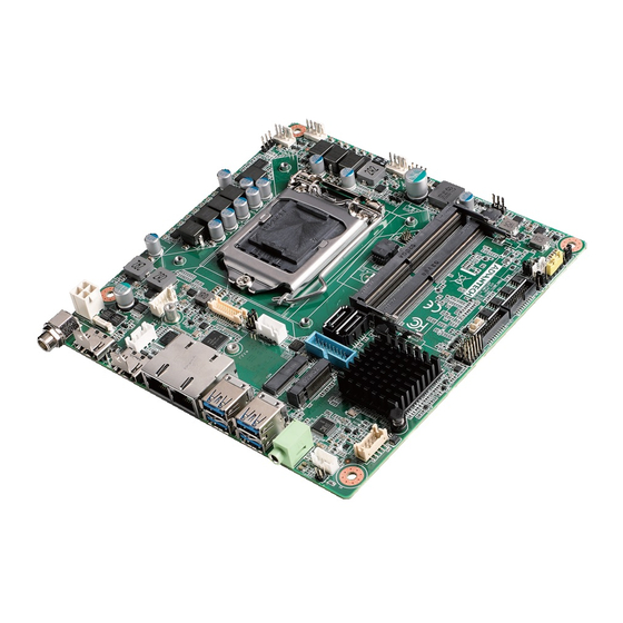
- Page 1 User Manual AIMB-287 Intel® Core™ i9/i7/i5/i3/Pentium/ Celeron LGA1200 Mini-ITX with Dual HDMI/eDP, 4 COM & 8 USB, 2 LAN, and M.2 E/M key...
- Page 2 No part of this manual may be reproduced, copied, translated, or transmitted in any form or by any means without the prior written permission of Advantech Co., Ltd. The information provided in this manual is intended to be accurate and reliable.
- Page 3 Advantech has come to be known. Your satisfaction is our primary concern. Here is a guide to Advantech’s cus- tomer services.
- Page 4 AQD-SD4U16N24- DDR4 2400 16GB Advantech H5AN8G8NCJ M.2 SSD Compatibility Bandwidth_ Dimension Interface Vendor Model ADVANTECH P/N Performance 2280 M.2 Key M PCIe v3.0 LITE-ON CA3-8D512 96FD80-P512-LIS S1TR191176010 SQF-CM8V4- 2280 M.2 Key B+M PCIe v3.0 Advantech 00002 960G-ECE AIMB-287 User Manual...
- Page 5 It should be free of marks and scratches and in perfect working order upon receipt. As you unpack the AIMB-287, check it for signs of ship- ping damage. (For example, damaged box, scratches, dents, etc.) If it is damaged or it fails to meet the specifications, notify our service department or your local sales representative immediately.
- Page 6 AIMB-287 User Manual...
-
Page 7: Table Of Contents
Figure 1.1 Jumper and Connector Location (Top Side)....5 Figure 1.2 Jumper and Connector Location (Bottom Side) ..6 AIMB-287 Board Diagram ................. 6 Figure 1.3 AIMB-287 Board Diagram .......... 6 Safety Precautions ..................7 Jumper Settings ..................7 1.8.1 How to Set Jumpers.............. - Page 8 Chipset Software Installation Utility..Before You Begin.................. 102 Introduction ................... 102 Chapter VGA Setup ........103 Introduction ................... 104 Windows 10 VGA Driver Installation ............. 104 Chapter LAN Configuration ......105 Introduction ................... 106 Features....................106 Installation..................... 106 AIMB-287 User Manual viii...
- Page 9 Windows® 10 Driver Setup (Intel i219LM&Intel i211AT) ..... 107 AIMB-287 User Manual...
- Page 10 AIMB-287 User Manual...
-
Page 11: Chapter 1 General Information
Chapter General Information... -
Page 12: Introduction
Introduction AIMB-287 is designed with the Intel® H420E PCH for industrial applications that require both performance computing and enhanced power management capabilities. The motherboard supports Intel desktop Corei9/i7/i5/i3/Pentium/Celeron processors, up to 20 MB SmartCache, and 2 x DDR4 2933MHz SO-DIMM, up to 64 GB. Multiple I/O connectivity of 4 x serial ports, 6 x USB 3.0 + 2 USB 2.0, 2 x GbE LAN, 2 x SATA... -
Page 13: Graphics
7.482A; +24V @3.72A . Measure the maximum current value which system under maximum load (CPU: Top speed, RAM & Graphic: Full loading). Board size: 170 mm x 170 mm (6.69" x 6.69"). Board weight: 0.365 kg. AIMB-287 User Manual... -
Page 14: Jumpers And Connectors
Jumpers and Connectors Connectors on the AIMB-287 motherboard link it to devices such as hard disk drives and a keyboard. In addition, the board has a number of jumpers used to configure the system for your application. The tables below list the function of each of the board jumpers and connectors. Later sections in this chapter give instructions on setting jumpers. -
Page 15: Board Layout: Jumper And Connector Locations
M2M1 M2E2 ATX12V1 USB78 INV1 SATA_PWR1 EDP1 USB0506 JEDP1 SATA1 SATA2 GPIO ESPI1 COM34 BAT1 SPI1 COM12 JCMOS1 JCASE1 JSETCOM1_V1 JWDT1+JOBS1 JSMB1 CPUFAN1 PSON1 ATX_5VSB1 SYSFAN2 JFP1 SYSFAN1 JFP2 Figure 1.1 Jumper and Connector Location (Top Side) AIMB-287 User Manual... -
Page 16: Aimb-287 Board Diagram
Figure 1.2 Jumper and Connector Location (Bottom Side) AIMB-287 Board Diagram Figure 1.3 AIMB-287 Board Diagram AIMB-287 User Manual... -
Page 17: Safety Precautions
1, 2, and 3. In this case you connect either pins 1 and 2, or 2 and 3. A pair of needle-nose pliers may be useful when set- ting jumpers. AIMB-287 User Manual... -
Page 18: Cmos Clear (Jcmos1)
1.8.2 CMOS Clear (JCMOS1) The AIMB-287 motherboard contains a jumper that can erase CMOS data and reset the system BIOS information. Normally this jumper should be set with pins 1-2 closed. If you want to reset the CMOS data, set CMOS1 to 2-3 closed for just a few seconds, and then move the jumper back to 1-2 closed. -
Page 19: Edp Panel Voltage Selection (Jlvds1)
Jumper position for +5V Jumper position for +12V 1.8.6 COM1 RI# Pin RI#/5V/12V Select (JSETCOM1_V1) Table 1.6: COM1 RI# Pin RI#/5V/12V Select (JSETCOM1_V1) Function Jumper Setting Jumper position for RI# (Default) Jumper position for +5V Jumper position for +12V AIMB-287 User Manual... -
Page 20: System Memory
System Memory AIMB-287 has two sockets for a 260-pin DDR4 SO-DIMM. These sockets use a 1.2 V unbuffered double data rate synchronous DRAM (DDR SDRAM). DRAM is available in capacities of 4GB, 8GB, 16GB and 32GB. The sockets can take any combination with SODIMMs of any size, giving a total memory size between 4GB, 8GB, 16GB, and up to max 64GB. -
Page 21: Chapter 2 Connecting Peripherals
Chapter Connecting Peripherals... -
Page 22: Introduction
If you have a number of cards installed or have a packed chassis, you may need to partially remove the card to make all the connections. DC Input Connector (DCIN1) Signal Pin Definition Power input (Only +12V~24V) AIMB-287 User Manual... -
Page 23: Definition Multimedia Interface (Hdmi1/2)
Definition Multimedia Interface (HDMI1/2) Signal Pin Definition Signal Pin Definition HDMI_D2+ HDMI_CLK- HDMI_D2- HDMI_D1+ HDMI_SCL HDMI_D1- HDMI_SDA HDMI_D0+ HDMI_D0- HMDI_HPD HDMI_CLK+ AIMB-287 User Manual... -
Page 24: Lan1/2(Rj45)
LAN1/2_3 MDI1+ LAN1/2_4 MDI2+ LAN1/2_5 MDI2- LAN1/2_6 MDI1- LAN1/2_7 MDI3+ LAN1/2_8 MDI3- LAN1/2_LED1 off for mal-link; Link (On)/Active (Flash) LAN1/2_LED2 100 Mbps (On)/10 Mbps (Off); Color: Orange (10/100 Mbps) LAN1/2_LED2 1000 Mbps (On); Color: Green (1000 Mbps) AIMB-287 User Manual... -
Page 25: Usb 3.0 Stack Connector (Usb12, Usb34)
USB 3.0 Stack Connector (USB12, USB34) Signal Pin Definition USB12/34_1 VBUS USB12/34_2 USB12/34_3 USB12/34_4 USB12/34_5 RX1- USB12/34_6 RX1+ USB12/34_7 USB12/34_8 TX1- USB12/34_9 TX1+ AIMB-287 User Manual... -
Page 26: Hd Analog Audio Interface (Audio1)
HD Analog Audio Interface (Audio1) Signal Pin Definition LINE OUT - L LINE OUT - R AIMB-287 User Manual... -
Page 27: Front Panel Audio Header (Jfpud1)
Front Panel Audio Header (JFPUD1) Signal Pin Definition AGND MIC-L Jack Detect MIC-R AIMB-287 User Manual... -
Page 28: Amplifier Connector (Amp1)
Amplifier Connector (AMP1) Signal Pin Definition AIMB-287 User Manual... -
Page 29: Usb 2.0 Pin Header (Usb78)
USB 2.0 Pin Header (USB78) Signal Pin Definition Signal Pin Definition VBUS VBUS AIMB-287 User Manual... -
Page 30: Ngff M.2 M-Key Connector For 2280 Module (M2M1)
2.10 NGFF M.2 M-Key Connector for 2280 Module (M2M1) M2M1 Signal Signal +3.3V +3.3V PCIE_RX3- PCIE_RX3+ PCIE_TX3- +3.3V PCIE_TX3+ +3.3V +3.3V PCIE_RX2- +3.3V PCIE_RX2+ PCIE_TX2- PCIE_TX2+ PCIE_RX1- PCIE_RX1+ PCIE_TX2- PCIE_TX2+ DEVSLP AIMB-287 User Manual... - Page 31 PCIE_RX0+ / SATA_RX+ PCIE_RX0- / SATA_RX- PCIE_TX0- / SATA_TX- PCIE_TX0+ / SATA_TX+ PLTRST# CLKREQ# PCIE_CLK- PCIEWAKE# PCIE_CLK+ SUSCLK SATA/PCIE DETECT +3.3V +3.3V +3.3V AIMB-287 User Manual...
-
Page 32: Ngff M.2 E-Key Connector For 2230 Module (M2E1)
NGFF M.2 E-Key Connector for 2230 Module (M2E1) M2E1 Signal Signal +3.3V USB_D+ +3.3V USB_D- WLAN_LED# BT_I2S_SCLK CNV_WGR_D1- BT_I2S_BCLK CNV_WGR_D1+ BT_I2S_SDO BT_I2S_SDI CNV_WGR_D0- BT_LED# CNV_WGR_D0+ BT_UART_WAKE# CNV_WGR_CLK- CNV_BRI_RSP CNV_WGR_CLK+ CNV_RGI_DT CNV_RGI_RSP PCIE_TX+ CNV_BRI_DT PCIE_TX- CL_RST# CL_DAT PCIE_RX+ CL_CLK PCIE_RX- CNV_GNSS_BLANKING AIMB-287 User Manual... -
Page 33: Serial Ata Interface Power Connector (Satapwr1/2)
CNV_MFUART2_TXD PCIE_CLK+ CNV_MFUART2_RXD PCIE_CLK- SUSCLK PLTRST# PCIE_CLKREQ# BT_DISABLE# PCIE_WAKE# WIFI_DISABLE# CNV_WT_D1- CNV_WT_D1+ REFCLK_38.4M CNV_WT_D0- PLTRST# CNV_WT_D0+ PCIE_WAKE# CNV_WT_CLK- +3.3V CNV_WT_CLK+ +3.3V 2.12 Serial ATA Interface Power Connector (SATAPWR1/2) SATAPWR2 SATAPWR1 Signal +12V AIMB-287 User Manual... -
Page 34: Voltage Selection For Edp1 Connector (Jedp1)
2.13 Voltage Selection for EDP1 Connector (JEDP1) JEDP1 Signal Signal +V12 +VDD_EDP +V3.3 AIMB-287 User Manual... -
Page 35: Embedded Displayport Connector (Edp1)
2.14 Embedded DisplayPort Connector (EDP1) EDP1 Signal Signal TX0- TX3- TX0+ TX3+ TX1- TX1+ AUX- AUX+ TX2- TX2+ +VDD_EDP +VDD_EDP AIMB-287 User Manual... -
Page 36: Edp Backlight Inverter Power Connector (Inv1)
2.15 EDP Backlight Inverter Power Connector (INV1) INV1 Signal +V12 Enable backlight Brightness control AIMB-287 User Manual... -
Page 37: Atx 12V Power Supply Connector (Atx12V1)
2.16 ATX 12V Power Supply Connector (ATX12V1) ATX12V1 Signal 12V ~ 24V 12V ~ 24V AIMB-287 User Manual... -
Page 38: Usb 3.1 Gen1 #5/ #6 (Usb0506)
2.17 USB 3.1 Gen1 #5/ #6 (USB0506) USB0506 Signal Signal VBUS RX1- RX1+ TX2+ TX1- TX2- TX1+ RX2+ RX2- VBUS AIMB-287 User Manual... -
Page 39: Serial Ata Interface Connector #1~#2 (Sata1~Sata2)
2.18 Serial ATA Interface Connector #1~#2 (SATA1~SATA2) SATA2 SATA1 Signal AIMB-287 User Manual... -
Page 40: Espi Interface Connector (Espi1)
2.19 eSPI Interface Connector (ESPI1) ESPI1 Signal Signal ESPI_IO1 ESPI_CLK ESPI_IO0 ESPI_RST# +V3.3 ESPI_CS0# ESPI_IO3 +V3.3_DUAL ESPI_IO2 AIMB-287 User Manual... -
Page 41: 8-Bit General Purpose I/O Pin Header (Gpio1)
2.20 8-bit General Purpose I/O Pin Header (GPIO1) GPIO1 Signal Signal GPIO0 GPIO4 GPIO1 GPIO5 GPIO2 GPIO6 GPIO3 GPIO7 +V5_DUAL AIMB-287 User Manual... -
Page 42: Com Port Pin Header #1/#2 (Com12)
2.21 COM Port Pin Header #1/#2 (COM12) COM12 Signal Signal COM1_DCD# COM1_DSR# COM1_SIN COM1_RTS# COM1_SOUT COM1_CTS# COM1_DDTR# COM1_RI# COM2_DCD# COM2_DSR# COM2_SIN COM2_RTS# COM2_SOUT COM2_CTS# COM2_DDTR# COM2_RI# AIMB-287 User Manual... - Page 43 RS-232 Signal RS-422** Signal RS-485** Signal DCD# DCD+ SOUT DTR# DTR+ DSR# RTS# CTS# DCD- DTR- Note! * : There is a cable marked in RED on COM#1 (TPN/MOQ required) **: COM1/2 BOM option RS422/495, default RS232 AIMB-287 User Manual...
-
Page 44: Com Port Pin Header #3/#4 (Com34)
2.22 COM Port Pin Header #3/#4 (COM34) COM34 Signal Signal COM3_DCD# COM3_DSR# COM3_SIN COM3_RTS# COM3_SOUT COM3_CTS# COM3_DDTR# COM3_RI# COM4_DCD# COM4_DSR# COM4_SIN COM4_RTS# COM4_SOUT COM4_CTS# COM4_DDTR# COM4_RI# AIMB-287 User Manual... - Page 45 Corresponding COM cable DB9 Conn. pin assignment (PN: 1700031130-01) RS-232 Signal DCD# SOUT DTR# DSR# RTS# CTS# Note! * : There is a cable marked in RED on COM#3 AIMB-287 User Manual...
-
Page 46: Case Open Connector (Jcase1)
2.23 Case Open Connector (JCASE1) JCASE1 Signal CASEOPEN# AIMB-287 User Manual... -
Page 47: Cmos Clear (Jcmos1)
2.24 CMOS clear (JCMOS1) JCMOS1 Function Jumper Setting Keep CMOS Data (Default) Clear CMOS Data AIMB-287 User Manual... -
Page 48: Watchdog Timer Output And Obs Beep (Jwdt1+ Jobs1)
2.25 Watchdog Timer Output and OBS Beep (JWDT1+ JOBS1) JWDT1+JOBS1 Function Jumper Setting Watchdog Timer Output (2-3) (Default) OBS BEEP(4-5) (Default) AIMB-287 User Manual... -
Page 49: Atx Supported 3-Pin Header On Board (Atx_5Vsb1)
2.26 ATX Supported 3-pin Header on Board (ATX_5VSB1) ATX_5VSB1 Signal +V5SB PS_ON# AIMB-287 User Manual... -
Page 50: Com1_Ri# Pin Ri# / 5V / 12V Selection (Jsetcom1_V1)
2.27 COM1_RI# Pin RI# / 5V / 12V Selection (JSETCOM1_V1) JSETCOM1_V1 Function Setting Jumper position for RI# (Default) Jumper position for +5V Jumper position for +12V AIMB-287 User Manual... -
Page 51: At/Atx Mode Selection (Pson1)
2.28 AT/ATX Mode Selection (PSON1) PSON1 Signal VCCAT +3.3V_DUAL VCCATX AIMB-287 User Manual... -
Page 52: Power Led Pin Header (Jfp2)
2.29 Power LED Pin Header (JFP2) JFP2 Signal PWR_LED+ N.C. PWR_LED- AIMB-287 User Manual... -
Page 53: Spi Programming Pin Header (Cn1)
2.30 SPI Programming Pin Header (CN1) Signal Signal +3.3V MISO MOSI AIMB-287 User Manual... -
Page 54: Spi Bios Flash Socket (Spi1)
2.31 SPI BIOS Flash Socket (SPI1) SPI1 Signal Signal MISO WP# / io2 MOSI HOLD# / io3 +3.3V AIMB-287 User Manual... - Page 55 2.32 PWRBTN#/ RESET#/HDD LED/ SM bus/ Ext. Speaker Header (JFP1) JFP1 Signal Signal HDD_LED+ PWRBTN# HDD_LED- SMB_DAT SYS_RESET# SMB_CLK AIMB-287 User Manual...
-
Page 56: Pwrbtn#/ Reset#/Hdd Led/ Sm Bus/ Ext. Speaker Header (Jfp1) 45 2.33 System Fan #1 Connector /System Fan #2 Connector (Sysfan1/2)
2.33 System Fan #1 Connector /System Fan #2 Connector (SYSFAN1/2) SYSFAN2 SYSFAN1 Signal FAN SPEED AIMB-287 User Manual... -
Page 57: Cpu Fan Connector (Cpufan1)
2.34 CPU FAN Connector (CPUFAN1) CPUFAN1 Signal FAN SPEED AIMB-287 User Manual... -
Page 58: Cmos Battery Connector (Bat1)
2.35 CMOS Battery Connector (BAT1) BAT1 Signal +VBAT AIMB-287 User Manual... -
Page 59: Bios Operation
Chapter BIOS Operation... -
Page 60: Introduction
Increase the numeric value or make changes <Page Down/-> Decrease the numeric value or make changes <F1> General help, for Setup Sub Menu <F2> Item help <F5> Loads previous values <F7> Loads setup defaults <F10> Saves all CMOS changes AIMB-287 User Manual... -
Page 61: Main Menu
System Date using the <Arrow> keys. Enter new values via the keyboard. Press the <Tab> or <Arrow> keys to move between fields. The date must be entered in MM/DD/YY format. The time must be entered in HH:MM:SS format. AIMB-287 User Manual... -
Page 62: Advanced Bios Features
Select an Advanced BIOS setup option by highlighting the text using the <Arrow> keys. All Advanced BIOS setup options are described in this section. The Advanced BIOS setup menu screen is shown below. The submenus are described in the following pages. AIMB-287 User Manual... - Page 63 3.2.2.1 Platform Misc Configuration Native PCIE Enable [Enable] Native ASPM [Auto] AIMB-287 User Manual...
- Page 64 3.2.2.2 CPU Configuration Advance → CPU Configuration CPU Flex Ratio Override [Disabled] Intel (VMX) Virtualization [Enabled] PECI [Enabled] Active Processor Cores [All] BIST [Disabled] AES [Enabled] AIMB-287 User Manual...
- Page 65 3.2.2.3 Power & Performance Advance → Power & Performance AIMB-287 User Manual...
- Page 66 C-state Un- demotion [C1 and C3] Package C-state Un-demotion [Disabled] Package C-state Demotion [Disabled] CState Pre-Wake [Enabled] IO MWAIT Redirection [Disabled] Package C-state Limit [C7] Time Unit [1024 ns] AIMB-287 User Manual...
- Page 67 GT - Power Management Control Advance →Power & Performance →GT - Power Management Control RC6 (Render Standby) [Enabled] Maximum GT frequency [Default Max Frequency] Disable Turbo GT frequency [Disabled] AIMB-287 User Manual...
- Page 68 ME State [Enabled] AIMB-287 User Manual...
- Page 69 SHA256 PCR Bank [Enabled] Pending operation [None] Platform Hierarchy [Enabled] Storage Hierarchy [Enabled] Endorsement Hierarchy [Enabled] TPM2.0 UEFI Spec Version [TCG_2] Physical Presence Spec Version [1.3] TPM 20 Interface Type [TIS] AIMB-287 User Manual...
- Page 70 3.2.2.5 ACPI Settings Advance →ACPI Settings Enable ACPI Auto Configuration [Disabled] Enable Hibernation [Enabled] ACPI Sleep State [S3 (Suspend to RAM)] AIMB-287 User Manual...
- Page 71 3.2.2.6 NCT6126D Super I/O Configuration Advance →NCT6126D Super I/O Configuration AIMB-287 User Manual...
- Page 72 Serial Port 1 Configuration Serial Port [Enabled] Device Settings: I/O=3F8h; IRQ =4 Change Settings [Auto] To select an optimal setting for serial port 1. RS485 Auto Flow Control Function [Disabled] AIMB-287 User Manual...
- Page 73 Serial Port 2 Configuration Serial Port [Enabled] Device Settings: I/O=2F8h; IRQ =3 Change Settings [Auto] To select an optimal setting for serial port 2. RS485 Auto Flow Control Function [Disabled] AIMB-287 User Manual...
- Page 74 Serial Port 3 Configuration Serial Port [Enabled] Device Settings: I/O=3E8h; IRQ =5 Change Settings [Auto] AIMB-287 User Manual...
- Page 75 Serial Port 4 Configuration Serial Port [Enabled] Device Settings: I/O=3E8h; IRQ =5 Change Settings [Auto] AIMB-287 User Manual...
- Page 76 Use this to set the ACPI shutdown temperature threshold. When the system reaches the shutdown temperature, it will be automatically shut down by ACPI OS to protect the system from overheating damage. Case Open Warning [Disabled] Wake On Ring [Disabled] Watch Dog Timer [Disabled] AIMB-287 User Manual...
- Page 77 CPU FAN Mode [SMART FAN IV Mode] The item shows you CPU temperature and fan speed (PWM) information. SYSFAN Mode [SMART FAN IV Mode] The item shows you system temperature and fan speed (PWM) information. AIMB-287 User Manual...
- Page 78 Digital I/O Configuration Advance →NCT6126D HW Monitor →Digital I/O Configuration Digital I/O Pin 1 - 16 [Input] AIMB-287 User Manual...
- Page 79 3.2.2.8 S5 RTC Wake Settings Advance →S5 RTC Wake Settings The item allows you enable or disable system wake up on alarm event. Wake system from S5 [Disabled] AIMB-287 User Manual...
- Page 80 3.2.2.9 Serial Port Console Redirection Advance →Serial Port Console Redirection Console Redirection [Disabled] AIMB-287 User Manual...
- Page 81 Redirection COM Port [COM1] Resolution [80x24] Redirect After POST [Always Enable] AIMB-287 User Manual...
- Page 82 3.2.2.10 Intel TXT Information Advance → Intel TXT Information AIMB-287 User Manual...
- Page 83 Advance →USB Configuration Legacy USB Support [Enabled] XHCI Hand-off [Enabled] USB Mass Storage Driver Support [Enabled] USB transfer time-out [20 sec] Device reset time-out [20 sec] Device power-up delay [Auto] SanDisk [Auto] AIMB-287 User Manual...
- Page 84 3.2.2.12 Network Stack Configuration Advance →Network Stack Configuration Network Stack [Disabled] AIMB-287 User Manual...
- Page 85 Re-install your OS in UEFI Mode. Change all of settings above as “Legacy”: * Boot option filter-> Legacy Only * Network -> Legacy * Storage -> Legacy * Video -> Legacy * Other PCI devices -> Legacy AIMB-287 User Manual...
- Page 86 3.2.2.14 NVMe Configuration Advance →NVMe Configuration AIMB-287 User Manual...
-
Page 87: Chipset Configuration Setting
Users can display a Chipset Setup option by highlighting it using the <Arrow> keys. All Chipset Setup options are described in this section. The Chipset Setup screens are shown below. The sub menus are described on the following pages. AIMB-287 User Manual... - Page 88 3.2.3.1 System Agent (SA) Configuration Chipset →System Agent (SA) Configuration VT-d [Enabled] AIMB-287 User Manual...
- Page 89 Max TOLUD (Dynamic) Allows you to set the maximum value of TOLUD. Dynamic assignment would adjust TOLUD automatically based on largest MMIO length of installed graphic controller. Fast Boot [Enabled] Enable or disable Fast Boot support. AIMB-287 User Manual...
- Page 90 Select DVMT 5.0 Pre-Allocated (Fixed) Graphics Memory size used by the Internal Graphics Device. DVMT Total Gfx Mem [256M] Select DVMT5.0 Total Graphic Memory size used by the Internal Graphics Device. PM Support [Enabled] PAVP [Enabled] AIMB-287 User Manual...
- Page 91 LCD Control Chipset→ System Agent (SA) Configuration→ Graphics Configuration→ LCD Con- trol EDP Brightness PWM Output [100] Backlight PWM Frequency Control [23.3 KHz] AIMB-287 User Manual...
- Page 92 3.2.3.2 PCH-I/O Configuration Chipset →PCH-I/O Configuration AIMB-287 User Manual...
- Page 93 PCI Express Configuration Chipset →PCH-I/O Configuration →PCI Express Configuration PCI Express Clock Gating [Enable] PCIe-USB Glitch W/A [Disable] AIMB-287 User Manual...
- Page 94 M.2 M-key Slot Chipset →PCH-I/O Configuration →M.2 M-key Slot M.2 M-Key slot [Enable] ASPM 4 [Auto] L1 Substates [L1.1 & L1.2] PCIe Speed [Auto] AIMB-287 User Manual...
- Page 95 Extra options Chipset →PCH-I/O Configuration → M.2 M-key Slot →Extra options Detect Non-Compliance Device [Disable] Prefetechable Memory Reserved Memory Alignment Prefetechable memory Alignment AIMB-287 User Manual...
- Page 96 LAN2 Controller Chipset →PCH-I/O Configuration→LAN2 Controller LAN2 Controller [Enable] ASPM 10 [Auto] L1 Substates [L1.1 & L1.2] PCIe Speed [Auto] AIMB-287 User Manual...
- Page 97 Extra options Chipset→PCH-I/O Configuration→LAN2 Controller→Extra options Detect Non-Compliance Device [Disable] Prefetechable Memory Reserved Memory Alignment Prefetechable memory Alignment AIMB-287 User Manual...
- Page 98 M.2 E-key Slot Chipset →PCH-I/O Configuration→M.2 E-key Slot M.2 E-Key slot [Enable] ASPM 11 [Auto] L1 Substates [L1.1 & L1.2] PCIe Speed [Auto] AIMB-287 User Manual...
- Page 99 Extra options Chipset →PCH-I/O Configuration →M.2 E-key Slot →Extra options Detect Non-Compliance Device [Disable] Prefetechable Memory Reserved Memory Alignment Prefetechable memory Alignment AIMB-287 User Manual...
- Page 100 DIT0 Configuration [Disabled ] Serial ATA Port 2 (SATA) Port 1 [Enabled] Spin Up Device [Disabled] SATA Device Type [Hard Disk Drive] SATA Port 1 DevS1p [Disabled] DIT0 Configuration [Disabled] AIMB-287 User Manual...
- Page 101 Security Configuration Chipset →PCH-I/O Configuration →Security Configuration RTC Memory Lock [Enabled] BIOS Lock [Enabled] AIMB-287 User Manual...
- Page 102 HD Audio Configuration Chipset →PCH-I/O Configuration→ HD Audio Configuration HD Audio [Enabled] AIMB-287 User Manual...
-
Page 103: Security
Select this option and press <ENTER> to access the sub menu, and then type in the password. Set the Administrator password. User Password Select this option and press <ENTER> to access the sub menu, and then type in the password. Set the User Password. AIMB-287 User Manual... -
Page 104: Boot Setting
On or off power on state for the NumLock. Quiet Boot [Disabled] If this option is set to disabled, the BIOS displays normal POST messages. If enabled, an OEM logo is shown instead of POST messages. AIMB-287 User Manual... -
Page 105: Save & Exit Configuration
Select this option to quit Setup without making any permanent changes to the system configuration. 1. Select Discard Changes and Reset from the Save & Exit menu and press <Enter>. The following message appears: Discard Changes and exit setup AIMB-287 User Manual... - Page 106 Select Restore Defaults from the Exit menu and press <Enter>. Save as User Default Save the all current settings as a user default. Restore User Default Restore all settings to user default values. Boot Override Shows the boot device types on the system. AIMB-287 User Manual...
-
Page 107: Software Introduction & Service
Chapter Software Introduction & Service... -
Page 108: Introduction
Introduction The mission of Advantech Embedded Software Services is to "Enhance quality of life with Advantech platforms and Microsoft® Windows® embedded technology." We enable Windows® Embedded software products on Advantech platforms to more effectively support the embedded computing community. Customers are freed from the hassle of dealing with multiple vendors (hardware suppliers, system integrators, embedded OS distributors) for projects. - Page 109 CPU speed depending on the system loading. System Throttling Refers to a series of methods for reducing power consump- tion in computers by lowering the clock frequency. This API allows the user to adjust the clock from 87.5% to 12.5%. AIMB-287 User Manual...
-
Page 110: Software Utility
The Monitoring is a utility for customer to monitor the sys- tem health, like voltage, CPU and system temperature and fan speed. These items are important to a device, if critical errors occur and are not solved immediately, permanent damage may be caused. AIMB-287 User Manual... -
Page 111: Chipset Software Installation Utility
Chapter Chipset Software Installation Utility... -
Page 112: Before You Begin
Before You Begin To facilitate the installation of the enhanced display drivers and utility software, read the instructions in this chapter carefully. The drivers for the AIMB-287 are located on the Advantech support website: http://support.advantech.com/Support/. The drivers on the support website will guide and link you to the utilities and drivers under a Win- dows system. -
Page 113: Vga Setup
Chapter VGA Setup... -
Page 114: Introduction
See Chapter 5 for information on installing the CSI util- ity. Download the driver from website on your computer. Navigate to the “AIMB- 287_Graphic_Win10 (64-bit)” folder and click “setup.exe” to complete the installation of the drivers for Windows 10. AIMB-287 User Manual... -
Page 115: Lan Configuration
Chapter LAN Configuration... -
Page 116: Introduction
Introduction The AIMB-287 has two Gigabit Ethernet LANs via dedicated PCI Express x1 lanes Intel i211AT and I219LM (Phi) that offer bandwidth of up to 500 MB/sec, eliminating the bottleneck of network data flow and incorporating Gigabit Ethernet at 1000 Mbps. - Page 117 Select the “Autorun” then navigate to the directory for your OS. Note! Before installing this driver, make sure the CSI utility has been installed in your system. See Chapter 5 for information on installing the CSI util- ity. AIMB-287 User Manual...
- Page 118 No part of this publication may be reproduced in any form or by any means, electronic, photocopying, recording or otherwise, without prior written permis- sion of the publisher. All brand and product names are trademarks or registered trademarks of their respective companies. © Advantech Co., Ltd. 2021...
Need help?
Do you have a question about the AIMB-287 and is the answer not in the manual?
Questions and answers