Sign In
Upload
Manuals
Brands
Advantech Manuals
Motherboard
AIMB-205
Advantech AIMB-205 Mini ITX Motherboard Manuals
Manuals and User Guides for Advantech AIMB-205 Mini ITX Motherboard. We have
1
Advantech AIMB-205 Mini ITX Motherboard manual available for free PDF download: User Manual
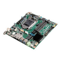
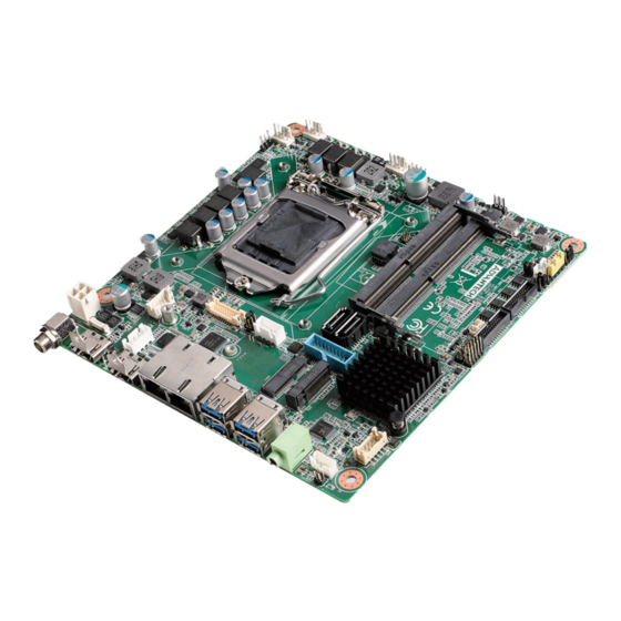
Advantech AIMB-205 User Manual (150 pages)
Intel Core i7/i5/i3/Pentium/ Celeron LGA1151 Mini-ITX with CRT/DVI-D/DP++/LVDS(or eDP), 8 COM & 14 USB, Dual LAN, PCIe x16
Brand:
Advantech
| Category:
Motherboard
| Size: 2 MB
Table of Contents
Declaration of Conformity
4
Ordering Information
6
Table of Contents
9
Chapter 1 General Information
13
Introduction
14
Features
14
Specifications
14
System
14
Memory
14
Input/Output
15
Graphics
15
Ethernet LAN
15
Industrial Features
15
Mechanical and Environmental Specifications
15
Jumpers and Connectors
16
Board Layout: Jumper and Connector Locations
17
Table 1.2: Jumper List
17
Figure 1.2 Jumper and Connector Location (Bottom Side)
18
AIMB-205 Board Diagram
19
Safety Precautions
19
Jumper Settings
20
CMOS Clear (JCMOS1)
20
How to Set Jumpers
20
Power Switch/Hdd Led/Smbus/Speaker Pin Header (JFP1)
20
(Jwdt1+Jobs1)
21
ATX/AT Mode Selection (PSON1)
21
Power LED and Keyboard Lock Pin Header (JFP2)
21
Watchdog Timer Output and OBS Beep (JWDT1+JOBS1)
21
COM1 RI# Pin RI#/5V/12V Select (JSETCOM1_V1)
22
Lvds/Edp Panel Voltage Selection (JLVDS1)
22
System Memory
22
Memory Installation Procedures
23
Cache Memory
23
Processor Installation
23
Chapter 2 Connecting Peripherals
25
Introduction
26
USB Ports (LAN1_USB12/LAN2_USB34/USB56/USB78/USB910)
26
VGA + DVI-D Connector (VGA1 + DVI1)
27
Serial Ports (COM1~COM8)
27
PS/2 Keyboard and Mouse Connector (KBMS1)
28
CPU Fan Connector (CPU_FAN1)
28
System FAN Connector (SYSFAN1/2)
29
Power Switch/Hdd Led/Smbus/Speaker Pin Header (JFP1) & Power
29
LED and Keyboard Lock Pin Header (JFP2)
29
ATX Soft Power Switch (JFP1/PWR_SW)
29
Reset (JFP1/RESET)
30
Hdd Led (Jfp1/Hddled)
30
External Speaker (JFP1/SPEAKER)
30
Power LED and Keyboard Lock Connector
30
Lock)
30
Display Port Connector (DP1)
31
ATX 12V Power Supply Connector (ATX12V1) & ATX Power Supply Connector (ATXPWR1)
31
SATA Signal Connector (SATA1 ~ SATA2)
32
HD Analog Audio Interface (AUDIO1, FPAUD1)
32
PCI-E X16 Slot (PCIEX16_1)
33
LVDS Panel Connector (LVDS1)
33
Lvds/Edp Backlight Inverter Power Connector (INV1)
34
Embedded Display Port Connector (EDP1), BOM Optional
35
MINIPCIE and Msata Connector (MINIPCIE1)
35
NGFF M.2 B-Key Connector for 2242 Module (M.2_2)
36
HD Digital Audio Interface (SPDIF1)
36
Audio Amplifier Output Connector (AMP1)
37
General Purpose I/O Pin Header (GPIO1)
37
SPI BIOS Flash Socket (SPI1)
38
SPI Programming Pin Header (SPI_CN1)
38
Low Pin Count Header (LPC1)
39
Case-Open Detect Connector (JCASE1)
39
Battery Holder (BAT1)
40
CPU Socket (CPU1)
40
DDR4 SO-DIMM Socket (DIMMA1, DIMMB1)
41
BIOS Operation
43
Chapter 3 BIOS Operation
43
Introduction
44
BIOS Setup
44
Main Menu
45
Advanced BIOS Features
46
Chipset Configuration Setting
86
Security
105
Boot
107
Save and Exit Configuration
108
Chapter 4 Software Introduction & Service
111
Introduction
112
Value-Added Software Services
112
Software API
112
Software Utility
114
Chapter 5 Chipset Software Installation Utility
115
Before You Begin
116
Introduction
116
USB Setup
117
Chapter 6 USB Setup
117
Introduction
118
Win 7 / 8.1 USB 3.0 Driver Installation
118
Chapter 7 VGA Setup
119
Introduction
120
Windows 7/8.1/10 VGA Driver Installation
120
Chapter 8 LAN Configuration
121
Introduction
122
Features
122
Installation
122
Windows® 7/8.1/10 Driver Setup (Realtek 8111G)
123
Appendix A I/O Pin Assignments
125
Keyboard & Mouse Connector (KBMS1)
126
Universal Serial Bus Port 7/8/9/10 (USB78910)
126
Digital Visual Interface Connector (DVI1)
127
Video Graphics Array Connector (VGA1)
127
Voltage Selector for JLVDS1 Connector (JLVDS1)
128
Embedded Displayport (EDP1), BOM Optional
128
LVDS VCON Pull Hi/Pull Low Selection (JLVDS_VCON1)
129
LVDS Panel Connector (LVDS1)
129
Displayport1(Dp1)
130
Dual USB2.0 Pin Header (USB56)
130
A.9 Displayport1(DP1)
130
RJ45 + USB3.0 Stack Connector (LAN1_USB12)
131
RJ45 + USB3.0 Stack Connector (LAN2_USB34)
132
HD Audio Interface (AUDIO1)
133
Amplifier Connector (AMP1)
133
Front Panel Audio Pin Header (FPAUD1)
134
HD Audio Interface (SPDIF1)
134
ATX 4 Pin Main Power Connector (ATX12V1)
134
PCI-Express X16 Slot (PCIEX16_1)
135
Cpu Scoket Lga1151 H4 (Cpu1)
137
System Fan #1/#2 Connector (SYSFAN1/ SYSFAN2)
137
Case Open Connector (JCASE1)
137
Case Open Selection Pin Header (JCASEOP_SW1)
138
CMOS Mode Selection (JCMOS1)
138
Power Switch/Hdd Led/Smbus/Speaker Pin Header (JFP1)
138
A.22 Case Open Selection Pin Header (JCASEOP_SW1)
138
CPU FAN Connector (CPUFAN1)
139
Power LED and Keyboard Lock Pin Header (JFP2)
139
SPI Pin Header (SPI_CN1)
139
MINIPCIE, Msata Connector (MINIPCIE1)
140
NGFF M.2 B-Key Connector for 2242 Module (M.2_2)
141
ATX 20Pin Power Connector (ATXPWR1)
142
SPI BIOS Flash Socket (SPI1)
143
Dual USB2.0 Pin Header (USB11/12 & USB13/14, BOM Optional)
143
COM5 ~ COM7 Box Header (COM5678)
144
AT/ATX Mode Selection (PSON1)
144
8-Bits General Purpose I/O Pin Header (GPIO1)
145
Low Pin Count Interface Connector (LPC1)
145
COM1 ~ COM4 Box Header (COM1234)
146
Watchdog Timer Output and OBS Beep (JWDT1+ JOBS1)
146
EDP/LVDS Backlight Inverter Power Connector (INV1)
147
CMOS Battery Connector (BAT1)
147
COM1 RI# Selection Pin Header (JSETCOM1_V1)
147
Advertisement
Advertisement
Related Products
Advantech AIMB-203
Advantech AIMB-203G2-00A1E
Advantech AIMB-203L-00A1E
Advantech AIMB-208
Advantech AIMB-203L
Advantech AIMB-203G2
Advantech AIMB-212D-S6A1E
Advantech AIMB-216
Advantech AIMB-232G2-U0B1E
Advantech AIMB-288EH-K1A1
Advantech Categories
Motherboard
Computer Hardware
Desktop
Touch Panel
Network Router
More Advantech Manuals
Login
Sign In
OR
Sign in with Facebook
Sign in with Google
Upload manual
Upload from disk
Upload from URL