
Related Manuals for REED R7900


Summary of Contents for REED R7900
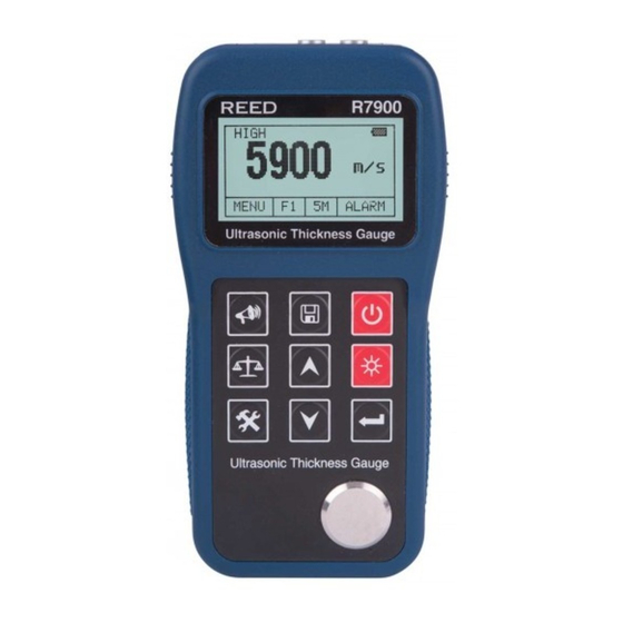
- Page 1 Rich Black - 20/20/20/100 R7900 Model Ultrasonic Thickness Gauge Only if you REALLY need them: Instruction Manual reedinstruments...
-
Page 2: Table Of Contents
Table of Contents Features ..................3 Specifications ................4-5 Instrument Description ..............6 Operating Instructions ..............7-10 Adjusting the Sound Velocity ............7 Setting Probe Frequency ............7 Preparing the Measurement Surface ........... 7 Taking Thickness Measurements ..........8 Zero Calibration ................8 Sound Velocity Measurements ............ -
Page 3: Features
Menu Options .................17-18 System Setup ................17 Print Function ................18 Memory Manager ..............18 Restore Factory Defaults ............18 Internal Memory Operation ............19 Reviewing Stored Data .............. 19 Maintenance ................19-20 Cleaning the Test Piece ............. 19 Protecting the Probe ..............19 Changing the Probe .............. -
Page 4: Specifications
Specifications Display: 128 x 64 LCD with LED backlight Measurement Range: 0.65 to 400.0mm (0.03 to 15.7”), dependant on materials and conditions Sound Velocity Range: 1000 to 9999m/s (0.039 to 0.394in/µs) Display Resolution: High: 0.01mm or 0.1mm (lower than 100.0mm) Low: 0.1mm (more than 99.99mm) Accuracy: ±0.04mm (lower than 10mm) - Page 5 Sound Velocity for Different Materials Sound velocity Material (m/s) (inch/µs) Aluminum 6320 to 6400 0.250 Zinc 4170 0.164 Silver 3607 0.142 Gold 3251 0.128 2960 0.117 Steel, Common 5920 0.233 Steel, Stainless 5740 0.226 Brass 4399 0.173 Copper 4720 0.186 Iron 5930 0.233...
-
Page 6: Instrument Description
Instrument Description Probe Socket RS-232 Socket Probe Test piece Keypad Description Velocity Button Save/Browse Data Power On/Off Button Zero Button Up Button Backlight On/Off Button Mode Button Down Button Enter Button Display Description Coupling Indicator Gain Indicator Minimum Capture Mode Battery Indicator Main Display Area Alarm Thickness Limit... -
Page 7: Operating Instructions
Operating Instructions Insert the probe into the probe socket on the meter Press the Power Button to turn the meter on The LCD will briefly display information about the meter, and then show the current set sound velocity Adjusting the Sound Velocity This instrument can display five sound velocities alternatively. -
Page 8: Taking Thickness Measurements
Taking Thickness Measurements Set the Sound Velocity on the meter Coat the piece to be measured with coupling agent Place the probe on the area and the Coupling Indicator will appear on the LCD Read the measurement on the LCD When you remove the probe the value will stay on the LCD and the Coupling Indicator will disappear Press the Save Button to save the measurement... -
Page 9: Sound Velocity Measurements
Sound Velocity Measurements The sound velocity of a material can be measured using a test piece with known thickness. Select a test piece with a minimum wall thickness of 20.0mm. Turn off the minimum capturing function prior to taking measurement. Measure the test piece with a calliper or micrometer Measure the test piece with the probe until it displays a value and remove the probe... -
Page 10: Minimum Capture Measurements
Minimum Capture Measurements When the probe couples with the work piece it will display the current measurement. When the probe is lifted away it will display the minimum value of the measurement carried out while the MIN Indicator flashes for several seconds. -
Page 11: Measurement Methods
Measurement Methods There are three base measurement methods: • Single Measurement: Measurement at one point. • Double Measurement: Measure one point twice. During the two measurements, the probe’s crosstalk interlayer plate should be placed in a perpendicular direction. Take the minimum readout as the accurate thickness of the material. -
Page 12: Measuring Compound Profiles
Measuring Compound Profiles When the material to be measured has a compound profile (such as bend of a pipe), one can use the procedures to measure cylindrical surfaces. The exception is that one should have two analyses and get two results when the probe’s crosstalk interlayer plate is being both parallel and perpendicular to the axial line of the object. -
Page 13: Measuring Castings
Measuring Castings Castings will cause large attenuations in sound energy due to coarse crystal particles and a not-so-dense structure. The attenuation is due to the material’s scatter and absorption of sound energy. Coarse out-phase structures and coarse crystal particles will cause abnormal reflection (i.e. -
Page 14: Preventing Errors
Preventing Errors Reference Test Pieces To maintain high accuracy when taking measurements of different materi- als it is important to use a standard test piece that resembles the material and conditions being measured. The ideal reference test pieces should be a group of test pieces with different thickness made of the same materials that is going to be measured. -
Page 15: Ultra-Thin Material
Ultra-thin Material An error will occur when the thickness of an object is less than the low limit of the probe. When necessary measure the minimum limit thickness by comparing it with test pieces. When measuring an ultra-thin object, sometimes errors called “double refraction” may occur. This results in a displayed readout that is twice the actual thickness. -
Page 16: Influence Of Metal Surface Oxidation
Influence of Metal Surface Oxidation Some metals can produce a dense oxidation layer on the surface, such as aluminum. Even though the layer is in close contact with the substrate and provides no obvious interface, the ultrasonic wave will have different transmitting speeds in these two materials which will cause an error. -
Page 17: Menu Options
Menu Options The Menu Function controls the settings and functions of the meter. To enter the Menu press the Mode Button to highlight the Menu option on the LCD and press the Enter Button. System Setup Highlight the System Setup option and press the Enter Button to enter this menu. -
Page 18: Print Function
Print Function Highlight the Print Function option and press the Enter Button to enter this menu. Press the Up and Down Buttons to scroll through the Print Function Menu. To adjust a value press the Enter Button to select it and press the Up and Down Buttons to adjust the value. -
Page 19: Internal Memory Operation
Internal Memory Operation The internal memory is divided into 5 files. Each can save 100 measurement values. Before saving data be sure to set file number first. Press the Mode Button to highlight the Save File Name on the Press the Enter Button to scroll through the memory files, F1 to F5 Press the Velocity Button to save and exit Reviewing Stored Data Press the Mode Button to highlight the Save File Name on the... -
Page 20: Changing The Probe
Changing the Probe The degradation and wear of the probe’s interlayer plate will influence measurements. Replace the probe when the following occurs: When measuring different thicknesses, it always displays the same value When plugging in the probe it has an echo indication or a mea- sured value displays without measuring Battery Replacement Turn the meter off... - Page 21 Notes _________________________________________ ________________________________________________ ________________________________________________ ________________________________________________ ________________________________________________ ________________________________________________ ________________________________________________ ________________________________________________ ________________________________________________ ________________________________________________ ________________________________________________ ________________________________________________ ________________________________________________ ________________________________________________ ________________________________________________ ________________________________________________ ________________________________________________ Blue - 100/80/30/5 534 Blue Yellow - 0/27/100/0 123 Yellow ________________________________________________ Red - 10/100/100/5 485 Red Yellow - 0/27/100/0 123 Yellow Blue - 100/80/30/5 534 Blue reedinstruments Rich Black -...
- Page 22 Notes _________________________________________ ________________________________________________ ________________________________________________ ________________________________________________ ________________________________________________ ________________________________________________ ________________________________________________ ________________________________________________ ________________________________________________ ________________________________________________ ________________________________________________ ________________________________________________ ________________________________________________ ________________________________________________ ________________________________________________ ________________________________________________ ________________________________________________ Blue - 100/80/30/5 534 Blue Yellow - 0/27/100/0 123 Yellow ________________________________________________ Red - 10/100/100/5 485 Red Yellow - 0/27/100/0 123 Yellow Blue - 100/80/30/5 534 Blue reedinstruments Rich Black -...
Need help?
Do you have a question about the R7900 and is the answer not in the manual?
Questions and answers