Table of Contents
Advertisement
Advertisement
Table of Contents

Related Manuals for Kirby Morgan KMB-18 A/B


Summary of Contents for Kirby Morgan KMB-18 A/B
- Page 1 Kirby Morgan Band Mask KMB-18 A/B and KMB-28B Operations and Maintenance Manual...
- Page 2 KMB 18 & 28 MANUAL This page not used at this time. © Copyright 1970-2003 Kirby Morgan Dive Systems, Inc. All rights reserved. Document # 010518001...
- Page 3 © Copyright 1970-2003 Kirby Morgan Dive Systems, Inc. All rights reserved. This manual is made available for the express use of owner of this Kirby Morgan product. No part of this manual may be reproduced, stored in any retrieval system, or transmitted, or used in any form or by any means, whether graphic, electronic, mechanical, photocopy, or otherwise by technology known or unknown, without the prior written permission of Kirby Mor- gan Dive Systems, Inc.
- Page 4 KMB 18 & 28 MANUAL This page not used at this time. © Copyright 1970-2003 Kirby Morgan Dive Systems, Inc. All rights reserved. Document # 010518001...
-
Page 5: Table Of Contents
2.2.5 Connecting the Band Mask to the Diver’s Umbilical ............. 20 2.2.6 Gas Flow Systems Check ....................... 21 2.2.7 Sealing Integrity Check ......................22 2.2.8 Check Communications ......................22 Document # 010518001 © Copyright 1970-2003 Kirby Morgan Dive Systems, Inc. All rights reserved. - Page 6 4.3 EVERY SIX MONTHS OR 200 OPERATING HOURS............35 4.4 YEARLY OR EVERY 400 OPERATING HOURS ..............36 Chapter 5 PREVENTATIVE MAINTENANCE ................37 5.1 INTRODUCTION ........................37 © Copyright 1970-2003 Kirby Morgan Dive Systems, Inc. All rights reserved. Document # 010518001...
- Page 7 6.3.3 Face Port and Nose Block Replacement................. 55 COMMUNICATIONS SYSTEM ..................... 57 6.4.1 General............................ 57 6.4.2 Earphone Inspection ....................... 57 6.4.3 Microphone Removal and Replacement................. 58 Document # 010518001 © Copyright 1970-2003 Kirby Morgan Dive Systems, Inc. All rights reserved.
- Page 8 6.9.2 Removal of the Bent Tube Assembly ..................72 6.9.3 Inspection of Bent Tube Assembly ..................72 6.9.4 Replacement of the Bent Tube Assembly ................73 6.10 NOSE BLOCK ASSEMBLY ....................74 © Copyright 1970-2003 Kirby Morgan Dive Systems, Inc. All rights reserved. Document # 010518001...
- Page 9 7.5 USE OF QUICK-DISCONNECT ..................... 88 7.6 MASK CARRYING BAG ......................88 Appendix I Torque Specifictions ..................... 89 Appendix 2 Maintenance Log ......................90 Table of Equivalents ......................... 91 Document # 010518001 © Copyright 1970-2003 Kirby Morgan Dive Systems, Inc. All rights reserved.
- Page 10 KMB 18 & 28 MANUAL This page not used at this time © Copyright 1970-2003 Kirby Morgan Dive Systems, Inc. All rights reserved. Document # 010518001...
-
Page 11: Definition Of Signal Words
If you have any questions regarding the information in this manual, or the operation of your mask, call Kirby Morgan Dive Systems, Inc. at (805) 965-8538 or E-Mail: Info@KMDSI.com Document # 010518001 © Copyright 1970-2003 Kirby Morgan Dive Systems, Inc. All rights reserved. page 1... -
Page 12: Important Safety Information
KMB 18 & 28 MANUAL IMPORTANT SAFETY INFORMATION This Kirby Morgan Band Mask (KMB 18 A/B & 28) diving mask is intended for use only by trained divers who have successfully completed a recognized training course in surface supplied diving. - Page 13 All Kirby Morgan helmets and masks must not be used with oxygen breathing mixtures in excess of 50% by volume without first insuring all gas transporting components have been cleaned and lubricated for oxygen service.
-
Page 14: Warranty Information
Warranty Information Kirby Morgan Dive Systems, Inc. (KMDSI) warrants every new mask, helmet, or Dive Control System (DCS) to be free from defects in workmanship for a period of ninety (90) days from date of purchase. This warranty does not cover rubber parts or communications components. - Page 15 KMB 18 & 28 MANUAL This page not used at this time Document # 010518001 © Copyright 1970-2003 Kirby Morgan Dive Systems, Inc. All rights reserved. page 5...
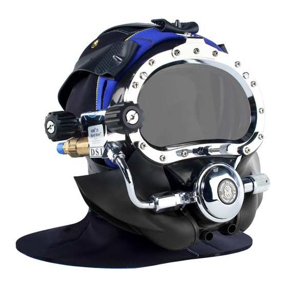
- Page 16 Port Equalizing Sideblock device Auxiliary valve knob One-way valve Regulator adjustment knob Regulator Hood The KMB 18B Band Mask (shown with optional Hard Shell) © Copyright 1970-2003 Kirby Morgan Dive Systems, Inc. All rights reserved. Document # 010518001 page 6...
-
Page 17: Chapter 1 General Information
Always specify the mask model number as well. There is only one exploded view drawing which includes both the Kirby Morgan Band Mask (KMB 18A) and Kirby Morgan Band Mask (KMB 18B), as well as the Kirby Morgan KMB 28 Band Mask. - Page 18 100-150 fsw (30-50 msw),135-225 psig (9.3-15.5 bar). 100-220 fsw (30-67 msw),175-225 psig (12.0-15.5 The mask has been tested and conforms to the bar). performance requirements as set forth in Annex page 8 © Copyright 1970-2003 Kirby Morgan Dive Systems, Inc. All rights reserved. Document # 010518001...
- Page 19 Use of a KMB 18/28 mask cannot prevent this type of injury. page 9 Document # 010518001 © Copyright 1970-2003 Kirby Morgan Dive Systems, Inc. All rights reserved.
-
Page 20: Kmb 18A, Kmb 18 B And Kmb 28 Band Mask Configurations
(117a) with its inlet nipple control station. (61a), and the bent tube assembly (117b) with its page 10 © Copyright 1970-2003 Kirby Morgan Dive Systems, Inc. All rights reserved. Document # 010518001... -
Page 21: Construction Specifications
“squeezed”, KIRBY MORGAN BAND MASK a very serious accident. Although we have se- KMB 18A/B & 28 Weight: 11 pounds page 11 Document # 010518001 © Copyright 1970-2003 Kirby Morgan Dive Systems, Inc. All rights reserved. - Page 22 (21) which directs the gas onto the face port (27) to prevent fogging that forms there from the page 12 © Copyright 1970-2003 Kirby Morgan Dive Systems, Inc. All rights reserved. Document # 010518001...
-
Page 23: Auxiliary Gas Supply System
Do not use a high pressure hose as the system on the helmet is not designed for high pressure. page 13 Document # 010518001 © Copyright 1970-2003 Kirby Morgan Dive Systems, Inc. All rights reserved. -
Page 24: Reducing Carbon Dioxide
(52) is positioned lower than the main buildup. exhaust (66) during a dive. The diver does not encounter this resistance as he exhausts out of the regulator exhaust. page 14 © Copyright 1970-2003 Kirby Morgan Dive Systems, Inc. All rights reserved. Document # 010518001... -
Page 25: Communications
KMDSI dealer. demand regulator assembly (63a/b). These tools make regulator adjustment much easier. The tool kit comes in a convenient, wallet sized pouch with instructions. page 15 Document # 010518001 © Copyright 1970-2003 Kirby Morgan Dive Systems, Inc. All rights reserved. - Page 26 Improperly manufactured parts can cause accidents. page 16 © Copyright 1970-2003 Kirby Morgan Dive Systems, Inc. All rights reserved. Document # 010518001...
-
Page 27: Chapter 2 Operating Instructions
KMDSI dealer if the ditions or exceed the product’s intended service. Band Mask has been damaged in shipment. page 17 Document # 010518001 © Copyright 1970-2003 Kirby Morgan Dive Systems, Inc. All rights reserved. -
Page 28: Pre Dress-In Procedure
(see torque specs pg. 89) (17). When the screw are adjusted properly, the hood and face seal cannot be moved from under the bands. page 18 © Copyright 1970-2003 Kirby Morgan Dive Systems, Inc. All rights reserved. Document # 010518001... -
Page 29: Clean Face Port
(47), the defogger control knob (85), auxiliary knob (100), and the nose block device knob (34) to ensure smooth and proper operation. page 19 Document # 010518001 © Copyright 1970-2003 Kirby Morgan Dive Systems, Inc. All rights reserved. -
Page 30: Connecting The Band Mask To The Diver's Umbilical
In extreme cases this could be fatal. Fig. 2.4 Always use two wrenches to connect the umbilical to the KMB 18A/B or 28. page 20 © Copyright 1970-2003 Kirby Morgan Dive Systems, Inc. All rights reserved. Document # 010518001... -
Page 31: Gas Flow Systems Check
Press in on gether with electrical tape prior to diving. the purge button (51d) in the regulator cover (51b). A strong burst of gas should follow. page 21 Document # 010518001 © Copyright 1970-2003 Kirby Morgan Dive Systems, Inc. All rights reserved. -
Page 32: Sealing Integrity Check
In addition, the mask may flood with water, causing drowning and/ or death. It is the diver’s responsibility to make sure a good seal is present. page 22 © Copyright 1970-2003 Kirby Morgan Dive Systems, Inc. All rights reserved. Document # 010518001... -
Page 33: Bleeding The Umbilical
If the mask is not going to be used immediately, it should be recapped. Fig. 2.10 The diver must always wear a bail-out bottle. page 23 Document # 010518001 © Copyright 1970-2003 Kirby Morgan Dive Systems, Inc. All rights reserved. - Page 34 The bail-out must be matched to the water depth and filled with the appropriate breathing gas. page 24 © Copyright 1970-2003 Kirby Morgan Dive Systems, Inc. All rights reserved. Document # 010518001...
- Page 35 The diver could be exposed to a serious “squeeze”. page 25 Document # 010518001 © Copyright 1970-2003 Kirby Morgan Dive Systems, Inc. All rights reserved.
-
Page 36: Securing The Band Mask On The Diver
If you have an “average” size head, the adjust- ment most divers find comfortable is three holes Fig. 2.15 You must be capable of donning your Band Mask by yourself. page 26 © Copyright 1970-2003 Kirby Morgan Dive Systems, Inc. All rights reserved. Document # 010518001... -
Page 37: Attaching The Umbilical To The Harness
To help keep the bib of your hood from floating up, you may want to tuck the bib of the hood under your harness. page 27 Document # 010518001 © Copyright 1970-2003 Kirby Morgan Dive Systems, Inc. All rights reserved. -
Page 38: Diver Check Gas Flow Systems
O.K. umbilical supply pressure. page 28 © Copyright 1970-2003 Kirby Morgan Dive Systems, Inc. All rights reserved. Document # 010518001... -
Page 39: Emergency Procedures
The top of the open bottom bell must be filled with the correct breathing gas for the diver’s depth. In addition, the bell must be equipped with communications. page 29 Document # 010518001 © Copyright 1970-2003 Kirby Morgan Dive Systems, Inc. All rights reserved. -
Page 40: Demand Regulator Free Flow
Drowning bag to protect it. KMDSI’s mask bag, Part Num- may result. ber 500-901, is designed for this purpose. page 30 © Copyright 1970-2003 Kirby Morgan Dive Systems, Inc. All rights reserved. Document # 010518001... -
Page 41: Chapter 3 Troubleshooting
TROUBLESHOOTING 3.1 GENERAL The Kirby Morgan 18A/B and 28B are highly reliable diving Band Masks which should not malfunction if proper preventative maintenance procedures are followed. Most problems encountered in using the Band Mask can be easily remedied. The following information covers most potential operating difficulties. -
Page 42: One-Way Valve Malfunction
Probable Cause Remedy 3.4 SIDE BLOCK (119A/B) MALFUNCTION Symptoms Probable Cause Remedy . f f l l i i l i & ( . ) page 32 © Copyright 1970-2003 Kirby Morgan Dive Systems, Inc. All rights reserved. Document # 010518001... -
Page 43: Demand Regulator Malfunction
KMB 18 & 28 MANUAL 3.5 DEMAND REGULATOR (63A/B) MALFUNCTION Symptoms Probable Cause Remedy i l i . t s page 33 Document # 010518001 © Copyright 1970-2003 Kirby Morgan Dive Systems, Inc. All rights reserved. -
Page 44: Water Leakage Into Band Mask
3.7 AUXILIARY VALVE (103) MALFUNCTION Symptoms Probable Cause Remedy s l i . e l i f f , e l l l i page 34 © Copyright 1970-2003 Kirby Morgan Dive Systems, Inc. All rights reserved. Document # 010518001... -
Page 45: Chapter 4 Inspection/Maintenance Timetable
4.3 EVERY SIX MONTHS OR 200 OPERATING HOURS 1) Replace inlet valve (59) and nut (53). See Section 6.14.3 2) Replace communications set (13). See Section 6.4 page 35 Document # 010518001 © Copyright 1970-2003 Kirby Morgan Dive Systems, Inc. All rights reserved. -
Page 46: Yearly Or Every 400 Operating Hours
10) Replace oral nasal (9). See Section 6.15 11) Replace hood (2). See Section 5.7 12) Test Port Retainer Inserts (this is a dealer provided service) page 36 © Copyright 1970-2003 Kirby Morgan Dive Systems, Inc. All rights reserved. Document # 010518001... -
Page 47: Chapter 5 Preventative Maintenance
Fig. 5.1 Always use the correct tools when performing 7/8 inch open end wrench maintenance on your KMB 18A/B or 28. 1 inch open end wrench page 37 Document # 010518001 © Copyright 1970-2003 Kirby Morgan Dive Systems, Inc. All rights reserved. -
Page 48: Component And Parts Cleaning
Teflon tape to travel lubricated for oxygen service. Only lubri- into the breathing system. cants such as Krytox ® or Halocarbon ® acceptable for oxygen service. page 38 © Copyright 1970-2003 Kirby Morgan Dive Systems, Inc. All rights reserved. Document # 010518001... -
Page 49: General
In addi- tion, the hose can whip about causing injury to anyone standing nearby. Fig. 5.3 Remove the hood by unscrewing the band screws. page 39 Document # 010518001 © Copyright 1970-2003 Kirby Morgan Dive Systems, Inc. All rights reserved. - Page 50 Fig. 5.5 The mask should be rinsed thoroughly with the bands to the point where the bands almost fresh water at the end of each diving day. touch. page 40 © Copyright 1970-2003 Kirby Morgan Dive Systems, Inc. All rights reserved. Document # 010518001...
-
Page 51: Monthly Maintenance (Or Between Jobs)
This could lead to drowning. page 41 Document # 010518001 © Copyright 1970-2003 Kirby Morgan Dive Systems, Inc. All rights reserved. -
Page 52: One-Way Valve
(KMDSI Part #525-330). (112) in a vise while removing the seat (106) with a wrench. page 42 © Copyright 1970-2003 Kirby Morgan Dive Systems, Inc. All rights reserved. Document # 010518001... -
Page 53: Reassembly Of The One-Way Valve
5) If the adapter (105) has been removed, it should be wrapped with Teflon tape on the ta- pered pipe threads and reinstalled at this time. Tighten the adapter. page 43 Document # 010518001 © Copyright 1970-2003 Kirby Morgan Dive Systems, Inc. All rights reserved. -
Page 54: Demand Regulator
Fig. 5.13 Back the regulator adjustment knob all the way component leakage. out when the mask will not be used for more than a few hours. page 44 © Copyright 1970-2003 Kirby Morgan Dive Systems, Inc. All rights reserved. Document # 010518001... -
Page 55: Inspection Of Regulator Body Interior
(43). Be careful or damage may result to the adjustment shaft (43). 7) Reinstall the diaphragm (52), cover (51b), and clamp (50). Tighten the clamp screw (49). page 45 Document # 010518001 © Copyright 1970-2003 Kirby Morgan Dive Systems, Inc. All rights reserved. - Page 56 (120a/b) at the top) and shake out the spacer (42), spring set (41), and piston (40). 6) Clean and lubricate generously with silicone grease. page 46 © Copyright 1970-2003 Kirby Morgan Dive Systems, Inc. All rights reserved. Document # 010518001...
-
Page 57: Reassembly Of Adjustment System
2) Place the washer (44) and O-ring (45) on the shaft (43). Fig. 5.21 Tighten the packing nut with the torque wrench. Fig. 5.20 Replace the washer and O-ring if necessary. page 47 Document # 010518001 © Copyright 1970-2003 Kirby Morgan Dive Systems, Inc. All rights reserved. -
Page 58: Demand Regulator Internal Adjustment
(52) and cover (51) in place, and press tightly down on the cover to simulate the action of Fig. 5.22 Checking the play in the lever. the clamp. page 48 © Copyright 1970-2003 Kirby Morgan Dive Systems, Inc. All rights reserved. Document # 010518001... - Page 59 The lever must be bent if more adjustment is necessary. page 49 Document # 010518001 © Copyright 1970-2003 Kirby Morgan Dive Systems, Inc. All rights reserved.
-
Page 60: Hood And Face Seal
Make sure the spider legs of the head harness do not cover up the vent holes. page 50 © Copyright 1970-2003 Kirby Morgan Dive Systems, Inc. All rights reserved. Document # 010518001... - Page 61 Three wraps of this tape will se- curely hold the hood in place and if it is over- lapped onto the main frame (17) it will insure a perfect seal. page 51 Document # 010518001 © Copyright 1970-2003 Kirby Morgan Dive Systems, Inc. All rights reserved.
- Page 62 KMB 18 & 28 MANUAL NOTES page 52 © Copyright 1970-2003 Kirby Morgan Dive Systems, Inc. All rights reserved. Document # 010518001...
-
Page 63: Chapter 6 Corrective Maintenance
Fig. 6.1 The face port from the KMB 28 will not fit properly in a KMB 18A/B. NOTE THE GAP WHERE THE PORT DOES NOT PROPERLY FILL THE SPACE. page 53 Document # 010518001 © Copyright 1970-2003 Kirby Morgan Dive Systems, Inc. All rights reserved. -
Page 64: Face Port And Nose Block Device Removal
(26). Fig. 6.2 Remove the nose block device knob. Fig. 6.3 Remove the nose block packing nut. Fig. 6.4 Removing the port retainer screws. page 54 © Copyright 1970-2003 Kirby Morgan Dive Systems, Inc. All rights reserved. Document # 010518001... -
Page 65: Face Port And Nose Block Replacement
Failure to do so could lead to seal on a KMB 28 cannot be repaired and failure. requires the replacement of the mask frame. page 55 Document # 010518001 © Copyright 1970-2003 Kirby Morgan Dive Systems, Inc. All rights reserved. - Page 66 This could as not to damage the knurl & plating. cause the face port to fail after a minor impact. page 56 © Copyright 1970-2003 Kirby Morgan Dive Systems, Inc. All rights reserved. Document # 010518001...
-
Page 67: Communications System
4) If the rubber covers are not good, replace them (10, 11) can be carefully pulled out of the hood (2) also. for inspection and disassembly. page 57 Document # 010518001 © Copyright 1970-2003 Kirby Morgan Dive Systems, Inc. All rights reserved. -
Page 68: Microphone Removal And Replacement
(73) will allow water to leak into the mask. (See Section 6.4.6.2 for repair) Fig. 6.14 Remove the nut from the communications posts. page 58 © Copyright 1970-2003 Kirby Morgan Dive Systems, Inc. All rights reserved. Document # 010518001... -
Page 69: Earphone Removal And Replacement
(76, 74, - 81) from the mask frame (17). 5) Place the packing gland (76) in a vice and unscrew the packing nut (79). page 59 Document # 010518001 © Copyright 1970-2003 Kirby Morgan Dive Systems, Inc. All rights reserved. -
Page 70: Connector Replacement
3) Pull the communications post (73) away from the mask frame (17). Fig. 6.18 Slide the packing nut and ferrules onto the new connector. page 60 © Copyright 1970-2003 Kirby Morgan Dive Systems, Inc. All rights reserved. Document # 010518001... -
Page 71: Communications Post Replacement
(93) also extends into the interior of the Band Mask frame (17) far enough to secure the air train (21) by means of the washer (23) and nut (22). page 61 Document # 010518001 © Copyright 1970-2003 Kirby Morgan Dive Systems, Inc. All rights reserved. -
Page 72: Sideblock Assembly Removal
4) The side block assembly (120b) is ready to start Fig. 6.21 The hose assembly must be removed prior to removal. removal of the side block. page 62 © Copyright 1970-2003 Kirby Morgan Dive Systems, Inc. All rights reserved. Document # 010518001... -
Page 73: Separating The Sideblock Assembly From The Band Mask Frame
(19) and the air train standoff (24) would be removed. Fig. 6.24 Pull the bent tube assembly straight out of the regulator nipple. Fig. 6.26 Remove the stud nut. page 63 Document # 010518001 © Copyright 1970-2003 Kirby Morgan Dive Systems, Inc. All rights reserved. -
Page 74: Sideblock Assembly Replacement
(RTV) away from both sealing surfaces before reassembling. Lacquer thinner helps remove this, but carefully since it will also remove the flat black finish inside the KMB 18 Band Mask. page 64 © Copyright 1970-2003 Kirby Morgan Dive Systems, Inc. All rights reserved. Document # 010518001... - Page 75 (RTV) is blocking the air flow to the Band Mask. If it is, it must be cleaned out prior to diving. page 65 Document # 010518001 © Copyright 1970-2003 Kirby Morgan Dive Systems, Inc. All rights reserved.
-
Page 76: Defogger Valve
This allows the knob locknuts to be loosened or tightened while allowing for the threaded stem end. Fig. 6.33 Components of the A & B sideblocks. page 66 © Copyright 1970-2003 Kirby Morgan Dive Systems, Inc. All rights reserved. Document # 010518001... -
Page 77: Cleaning And Lubricating
3) If the stem (91) remains in the side block body onto the stem (91). (94a/b) it can be lifted out after the bonnet (87) is removed. page 67 Document # 010518001 © Copyright 1970-2003 Kirby Morgan Dive Systems, Inc. All rights reserved. -
Page 78: Auxiliary Gas Supply Valve Assembly
(94a/b). It is a separate com- ponent that can be removed and replaced, or disassembled in place on the side block assembly Fig. 6.37 Disassembly of the auxiliary valve. page 68 © Copyright 1970-2003 Kirby Morgan Dive Systems, Inc. All rights reserved. Document # 010518001... -
Page 79: Reassembly Of Auxiliary Valve
18A) may be reinstalled. 8) Tighten the packing nut (99) with a wrench until friction, or moderate resistance is felt when turning the knob (100). page 69 Document # 010518001 © Copyright 1970-2003 Kirby Morgan Dive Systems, Inc. All rights reserved. -
Page 80: Model "A" Regulator Hose Assembly
11/16 inch Open End Attachment on Torque bubble leakage. This regulator end O-ring (118a) Wrench is removed by an O-ring removal tool. O-ring Removal Tool page 70 © Copyright 1970-2003 Kirby Morgan Dive Systems, Inc. All rights reserved. Document # 010518001... -
Page 81: Hose Replacement
O-ring is simple. Wipe with a light silicone grease coating, stretch onto the fitting, and slide until the O-ring (118a) snaps into the groove. Fig. 6.42 Replacing an "A" regulator hose. page 71 Document # 010518001 © Copyright 1970-2003 Kirby Morgan Dive Systems, Inc. All rights reserved. -
Page 82: B" Bent Tube Assembly
(61b) threads. It can be pushed up on the bent tube. Fig. 6.45 Replace the O-ring on the bent tube if it is worn. page 72 © Copyright 1970-2003 Kirby Morgan Dive Systems, Inc. All rights reserved. Document # 010518001... -
Page 83: Replacement Of The Bent Tube Assembly
Fig. 6.47 Tightening the jam nut. Fig. 6.46 You will probably need to loosen the regulator mount nut to position the bent tube. page 73 Document # 010518001 © Copyright 1970-2003 Kirby Morgan Dive Systems, Inc. All rights reserved. -
Page 84: Nose Block Assembly
Although this color is more durable than paint, it can be scratched and chipped. Light scratches can be remove using automotive rub- bing compound and waxing. page 74 © Copyright 1970-2003 Kirby Morgan Dive Systems, Inc. All rights reserved. Document # 010518001... -
Page 85: Rubber Whisker
A metal cup called the exhaust pulling it out. flange surrounds the rubber exhaust valve (62). plate (37) whisker (35) spacers (36) screw (38) Fig. 6.50 The whisker assembly. page 75 Document # 010518001 © Copyright 1970-2003 Kirby Morgan Dive Systems, Inc. All rights reserved. -
Page 86: Whisker Replacement
(36) on each side of the port retainer (28) and tighten to the correct torque. (see page 89) Do not overtighten. page 76 © Copyright 1970-2003 Kirby Morgan Dive Systems, Inc. All rights reserved. Document # 010518001... -
Page 87: Main Exhaust Assembly
This body is not replaceable and could require the replacement of the entire mask frame. Fig. 6.55 The main exhaust valve exposed on the KMB 18. page 77 Document # 010518001 © Copyright 1970-2003 Kirby Morgan Dive Systems, Inc. All rights reserved. -
Page 88: Demand Regulator Assembly
This makes on the Kirby Morgan Band Mask 18B or 28 must the maintenance of the demand regulator assem- be removed first. bly essential. page 78 © Copyright 1970-2003 Kirby Morgan Dive Systems, Inc. All rights reserved. Document # 010518001... -
Page 89: Disassembly Of The Demand Regulator
(52). If the purge button is to be replaced, using external retaining ring pliers, remove the retaining ring (51a), spring (51c) and button (51d) from the cover. page 79 Document # 010518001 © Copyright 1970-2003 Kirby Morgan Dive Systems, Inc. All rights reserved. -
Page 90: Inspection Of Demand Regulator Parts
Replace the whisker if nipple and press it onto the inlet valve. Also, the it allows bubbles to interfere with visibility. page 80 © Copyright 1970-2003 Kirby Morgan Dive Systems, Inc. All rights reserved. Document # 010518001... -
Page 91: Reassembly Of The Demand Regulator
Fig. 6.63 Use the KMDSI socket wrench to turn the nut on the inlet valve. 3) Place the spacer (54) onto the shaft of the inlet valve (59). page 81 Document # 010518001 © Copyright 1970-2003 Kirby Morgan Dive Systems, Inc. All rights reserved. - Page 92 (see pg 89). Make sure the adjustment knob (47) is run in simultaneously. Fig. 6.65 The adjustment knob must turn freely. 17) Replace the diaphragm (52). page 82 © Copyright 1970-2003 Kirby Morgan Dive Systems, Inc. All rights reserved. Document # 010518001...
-
Page 93: Unexplained Demand Regulator Steady Flow When Underwater
25) Attach the screws (38), plates (37) and spac- ers (36) on each side of the port retainer (28) and tighten to correct torque. (see pg 89) Do not overtighten. page 83 Document # 010518001 © Copyright 1970-2003 Kirby Morgan Dive Systems, Inc. All rights reserved. -
Page 94: Oral Nasal Mask
6.15.3 Oral Nasal Mask (9) Replacement 1) Snap the oral nasal mask (9) back over the regulator mount nut (8). 2) Reinstall the microphone (12). page 84 © Copyright 1970-2003 Kirby Morgan Dive Systems, Inc. All rights reserved. Document # 010518001... -
Page 95: Chapter 7 Accessories
1/4 inch Flat Blade Attachment on Locking Screw- driver 7/8 inch Open End Attachment on Torque Wrench 11/16 inch Open End Attachment on Torque Wrench Fig. 7.2 Install the regulator cover. page 85 Document # 010518001 © Copyright 1970-2003 Kirby Morgan Dive Systems, Inc. All rights reserved. - Page 96 15) Reinstall the free flow knob (85), spring (84), and locknut (83). Fig. 7.4 Install the PVC flanges. 16) Reinstall the auxiliary valve knob (100), spring (101), and locknut (102). page 86 © Copyright 1970-2003 Kirby Morgan Dive Systems, Inc. All rights reserved. Document # 010518001...
-
Page 97: Low Pressure Inflator Hose Installation On The "B" Sideblock
KMDSI Flow Restrictor Adapter, KMDSI Fig. 7.8 The weld shield assembly. P/N 555-210 must be used. page 87 Document # 010518001 © Copyright 1970-2003 Kirby Morgan Dive Systems, Inc. All rights reserved. -
Page 98: Use Of Quick-Disconnect
Fig. 7.9 To help protect your mask during travel, use the mask carrying bag. Fig. 7.8 A quick disconnect will make it simpler to hook up your bail-out to your mask. page 88 © Copyright 1970-2003 Kirby Morgan Dive Systems, Inc. All rights reserved. Document # 010518001... -
Page 99: Appendix I Torque Specifictions
550-095 L.P. Plug 117a 555-152 Regulator hose, side block end 117a 555-152 Regulator hose, regulator end 117b 555-154 bent tube assy, side block end page 89 Document # 010518001 © Copyright 1970-2003 Kirby Morgan Dive Systems, Inc. All rights reserved. -
Page 100: Appendix 2 Maintenance Log
This page may be used as a template for creating blalnk pages to record all the maintenance performed on this product. Maintenance Log Kirby Morgan Band Mask Mask Serial #: Repair Date Work Performed Performed By Checked By page 90 © Copyright 1970-2003 Kirby Morgan Dive Systems, Inc. All rights reserved. Document # 010518001... -
Page 101: Table Of Equivalents
Inches of Mecury (Hg) 2.036 Quarts Gallons 0.25 Square Inches Square Feet Temperature ( F - 32) Temperature ( 0.5555 Tons (U.S.) Pounds 2000 Watts Horsepower 0.001341 page 91 Document # 010518001 © Copyright 1970-2003 Kirby Morgan Dive Systems, Inc. All rights reserved.
Need help?
Do you have a question about the KMB-18 A/B and is the answer not in the manual?
Questions and answers