Table of Contents
Advertisement
Quick Links
Kirby Morgan
Operations and Maintenance Manual
The KM37 helmet is covered by U.S. Patent #6,644, 307B2. Foreign and other patents pending.
E-Mail: KMDSI@KirbyMorgan.com, Web Site: www.KirbyMorgan.com
Manual prepared by KMDSI, Dive Lab, Inc. and Marine Marketing and Consulting.
NOTE: This manual is the most current for the Kirby Morgan 37 and 57 Helmet. It is page dated January 2013. Fu-
ture changes will be shown on page IV and the changed pages will carry the date of change. Previous manuals may
not reflect these updates.
Diving with compressed breathing gas is a hazardous activity. Even if you do everything
right there is always the danger that you may be killed or injured. No piece of diving
equipment can prevent the possibility that you may be killed or injured any time you
enter the water.
The Kirby Morgan 37 helmet is CE Approved and meets or exceeds all performance and testing require-
ments of all government and non-government testing agencies throughout the world. It is approved for
use on all commercial and military work underwater.
Kirby Morgan, SuperLite
®
SuperFlow
and DECA are all registered trademarks of Kirby Morgan Dive Systems, Inc. Use of these terms to describe products
®
that are not manufactured by KMDSI is illegal.
The two dimensional images (such as photographs and illustrations) of our products are © copyrighted and trademarks of Kirby
Morgan Dive Systems, Inc. The three dimensional forms of our products are trademark, trade design and trade dress protected.
© ⅯⅯⅩⅡ Kirby Morgan Dive Systems, Inc. All rights reserved. This manual is made available for the express use of the owner of
this Kirby Morgan product. No part of this manual may be reproduced, stored in any retrieval system, or transmitted, or used in any
form or by any means, whether graphic, electronic, mechanical, photocopy, or otherwise by technology known or unknown, without
the prior written permission of Kirby Morgan Dive Systems, Inc.
KMDSI Part # 100-073
Kirby Morgan Dive Systems, Inc.
Santa Maria, CA 93455, USA
Telephone (805) 928-7772, FAX (805) 928-0342
, BandMask, Band Mask, KMB, KMB-Band Mask, DSI, Diving Systems International, EXO, REX
Document Number
37 & 57 Helmets
®
1430 Jason Way
WARNING
130108002
™
,
®
Advertisement
Table of Contents

Related Manuals for Kirby Morgan 37


Summary of Contents for Kirby Morgan 37
- Page 1 Manual prepared by KMDSI, Dive Lab, Inc. and Marine Marketing and Consulting. NOTE: This manual is the most current for the Kirby Morgan 37 and 57 Helmet. It is page dated January 2013. Fu- ture changes will be shown on page IV and the changed pages will carry the date of change. Previous manuals may not reflect these updates.
-
Page 2: Warranty Information
® Warranty Information KMDSI warrants every new Mask, Helmet, Scuba Regulator, Manifold Block or Kirby Morgan Air Control System 5 (KMACS 5) (each, a Product) to be free from defects in workmanship for a period of three hun- dred sixty five (365) days from the date of purchase from a KMDSI authorized dealer. This warranty covers all metal and plastic parts, but does NOT cover rubber parts, communications components, or head and chin cushions. - Page 3 The buyer acknowledges that it has read this agreement, understands it, and is bound by its terms. © ⅯⅯⅩⅢ Kirby Morgan Dive Systems, Inc. All rights reserved. Document #130108002...
-
Page 4: Record Of Changes
® Record Of Changes It is the responsibility of the owner of this product to register their ownership with Kirby Morgan Dive Systems, Inc., by sending the warranty card provided. This card is to establish registration for any necessary warranty work and as a means of communication that allows KMDSI to contact the user regarding this product. - Page 5 We do not herein make any effort to teach the principles of diving. The information in this manual is intended for users of Kirby Morgan helmets and persons that maintain or service Kirby Morgan helmets.
-
Page 6: Table Of Contents
� � � � � � � � � � � � � � � � � � � � � � � � � � � � � � � � � � � � � � � � � � � � � � � � � � � � � � � � � � � � � � � � � � � � � � � � � � � � � � � � � � © ⅯⅯⅩⅢ Kirby Morgan Dive Systems, Inc. All rights reserved. Document #130108002... - Page 7 � � � � � � � � � � � � � � � � � � � � � � � � � � � � � � � � � � � � � � � � � � � � � � � � � � � � � � � � � � � � � � � � � � � � � � � � © ⅯⅯⅩⅢ Kirby Morgan Dive Systems, Inc. All rights reserved. Document #130108002...
- Page 8 � � � � � � � � � � � � � � � � � � � � � � � � � � � � � � � � � � � � � � � � � � � � � � � � � � � � � � � � � � � � � � � � � � � � � � � � � � � � � � � � � � VIII © ⅯⅯⅩⅢ Kirby Morgan Dive Systems, Inc. All rights reserved. Document #130108002...
- Page 9 � � � � � � � � � � � � � � � � � � � � � � � � � � � � � � � � � � � � � � � � � � � � � � � � � � � � � © ⅯⅯⅩⅢ Kirby Morgan Dive Systems, Inc. All rights reserved. Document #130108002...
-
Page 10: Chapter 8 Corrective Maintenance
� � � � � � � � � � � � � � � � � � � � � � � � � � � � � � � � � � � � � � � � � � � � � � � � � � � � � � � � © ⅯⅯⅩⅢ Kirby Morgan Dive Systems, Inc. All rights reserved. Document #130108002... - Page 11 Appendix 3 Table 3 SuperFlow 450 SS Balanced Regulator Continued ® � � � � � � � � � � � � � � � � � � � © ⅯⅯⅩⅢ Kirby Morgan Dive Systems, Inc. All rights reserved. Document #130108002...
- Page 12 � � � � � � � � � � � � � � � � � � � � � � � � � � � � � � � � � � � � � � � � � � � � � � � � � � � � � � � � � � � � � � � � � � � � � � � � � � � � � � � � � � � � � � � © ⅯⅯⅩⅢ Kirby Morgan Dive Systems, Inc. All rights reserved. Document #130108002...
-
Page 13: Definition Of Signal Words Used In This Manual
Important Safety Information: This Kirby Morgan diving helmet is intended for use by trained divers who have successfully completed a recognized training course in surface supplied diving. © ⅯⅯⅩⅢ Kirby Morgan Dive Systems, Inc. All rights reserved. Document #130108002... - Page 14 Diving is a life threatening occupation. Even if you do everything right you can still be killed or injured. None of the models of Kirby Morgan helmets or masks can prevent ac- cidents, injuries or death due to improper training, poor-health, improper supervision, improper job requirements, improper maintenance or acts of God.
- Page 15 27 pounds. KMDSI recommends that persons with a previous neck or back injury seek professional medical approval prior to engaging in surface supplied diving operations using any Kirby Morgan helmet. Use of any Kirby Morgan helmet with a pre- existing physical/medical condition may result in death or serious injury.
- Page 16 If you have any questions concerning this manual or the operation of your helmet, contact KMDSI (805) 928-7772 or at kmdsi@KirbyMorgan.com or Dive Lab Inc. (850) 235-2715 or at Divelab@aol.com © ⅯⅯⅩⅢ Kirby Morgan Dive Systems, Inc. All rights reserved. Document #130108002...
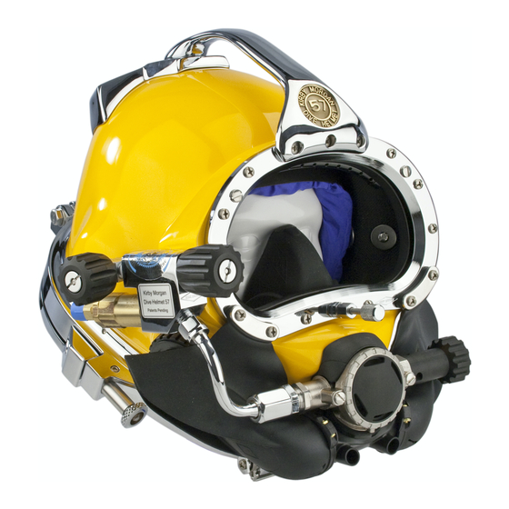
- Page 17 Non-Return Valve Pull Pin Purge Button Communications Port Quad Valve™ Exhaust (standard on all Kirby Morgan 37 helmets from 2005 on) The Kirby Morgan 37 helmet ™ © ⅯⅯⅩⅢ Kirby Morgan Dive Systems, Inc. All rights reserved. Document #130108002 XVII...
-
Page 19: Chapter 1 General Information Kmdsi Products
They are not the part number. Next to the exploded drawing is a list of the “location” numbers that match the Kirby Morgan part num- bers along with the name of the part. Always check the part number when ordering to make sure it is correct. -
Page 20: Full-Face Masks And Manifolds
2) no comfort insert is required on the 28 3) the face ports for the 18 and the 28 differ slightly in size. Both the KMB 18 and KMB 28 are approved. © ⅯⅯⅩⅢ Kirby Morgan Dive Systems, Inc. All rights reserved. Document #130108002... - Page 21 (tender) and one or more surface-supported divers, recompres- sion chambers, or other submersible systems. ™ SuperMask M-48 ™ marked w/ Rebreather pod © ⅯⅯⅩⅢ Kirby Morgan Dive Systems, Inc. All rights reserved. Document #130108002...
-
Page 22: Kirby Morgan Diving Helmets
SuperLite 17A/B Kirby Morgan ® ® ™ approved and marked approved and marked ™ ™ Yoke and Latch Catch Neck Pad and Assembly Sealed Pull Pins. © ⅯⅯⅩⅢ Kirby Morgan Dive Systems, Inc. All rights reserved. Document #130108002... - Page 23 In all other respects, this tube adjustable demand regulator. The helmet is helmet is nearly identical to the Kirby Morgan 37. available in the umbilical over the shoulder, “B” configuration only. © ⅯⅯⅩⅢ Kirby Morgan Dive Systems, Inc. All rights reserved. Document #130108002...
- Page 24 All helmets and suits can leak water under certain conditions. Divers should use extreme caution when diving in contaminated waters. © ⅯⅯⅩⅢ Kirby Morgan Dive Systems, Inc. All rights reserved. Document #130108002...
- Page 25 • Rugged helmet shell and other components • No refinishing required if the surface is scratched or gouged • Elimination of threaded inserts for securing port retainer to helmet shell © ⅯⅯⅩⅢ Kirby Morgan Dive Systems, Inc. All rights reserved. Document #130108002...
-
Page 27: Chapter 2 Description & Operational Specifications Kirby Morgan 37
WARNING This manual is our effort to explain the operation, maintenance and use of the KM 37 & 57. We do not herein make any effort to teach the principles of diving. It is our assumption the reader is a qualified diver. -
Page 28: 2�2�2 Notified Body
450 regulator. It is important that users understand how to use the tables. For further information on sup- ply requirements for the KM-37 or any Kirby Morgan ® © ⅯⅯⅩⅢ Kirby Morgan Dive Systems, Inc. All rights reserved. Document #130108002... -
Page 29: Helmet Features
Kirby Morgan website at www.kirbymorgan.com. Only equipment certified and tested according to EN 250/E DIN 58 642 may be used with the KM 37 helmet -Umbilical minimum I.D. 3/8” (9.5 mm) of not more when conducting diving operations in European EC than two sections, total length not to exceed 600 feet compliant countries. - Page 30 Kirby Morgan 37 & 57 ® The KM 37 was developed in 2003 and the 57 was developed in 2005. The goal was to bring together A quick change communications module, available all of the top design elements of the various Kirby...
- Page 31 O-ring. The seal is very air/ ing 3 knots) the single exhaust system water tight. The metal bottom of the KM 37 is more on all KMDSI masks/helmets could allow durable in normal use, but care should be taken not water to enter, due to turbulence/eddying.
-
Page 32: General Description
8) A system of two sealed pull pin locks is on the helmet to the umbilical in the event of a sudden lower- KM 37 & 57. One lock is located on each side of the ing of pressure in the umbilical. This can happen due helmet. -
Page 33: 2�8�3 Emergency Gas Supply System (Egs)
This compound and are quite robust. low-pressure area lowers the work of breathing and adds another barrier to water leaking in. © ⅯⅯⅩⅢ Kirby Morgan Dive Systems, Inc. All rights reserved. Document #130108002... - Page 34 O-ring Adjustment Lever nipple Main tube Lock clip Cover retaining ring Diaphragm Cover Exhaust valve Exhaust valve insert Retainer ring Exploded view of the SuperFlow 450 regulator. ® © ⅯⅯⅩⅢ Kirby Morgan Dive Systems, Inc. All rights reserved. Document #130108002...
- Page 35 Quad Valve exhaust. From there it ™ can exit through either of the exhaust valves and out through the whiskers. © ⅯⅯⅩⅢ Kirby Morgan Dive Systems, Inc. All rights reserved. Document #130108002...
-
Page 36: Emergency Gas Supply System (Egs)
(or air) fitted with a first stage regulator and hose that is connected to the inlet of the Emergency Gas Supply Valve (EGS). © ⅯⅯⅩⅢ Kirby Morgan Dive Systems, Inc. All rights reserved. Document #130108002... -
Page 37: 2�8�4 Helmet Attachment To The Diver
The Locking Collar Assembly. 2.8.4 Helmet Attachment to the Diver On the KM 37 and 57, the ring on the base of the O-ring helmet shell has a machined O-ring sealing surface. The O-ring that seals against this surface sits inside Neck the neck dam ring assembly. -
Page 38: 2�8�5 Sealing Arrangement
CAUTION erly mounted in the oral nasal mask. If the valve is mounted improperly or is absent this The fit of the KM 37 and 57 is partially deter- can lead to a higher CO level inside the hel- mined by the adjustment of the neck pad. If met. -
Page 39: 2�8�9 Face Port Or Viewing Lens
O-ring to leak. © ⅯⅯⅩⅢ Kirby Morgan Dive Systems, Inc. All rights reserved. Document #130108002... -
Page 40: 2�9�3 Special Regulator Tools For Superflow
(Part #525-620). This tool kit now ships standard with every Kirby Morgan helmet equipped with the SuperFlow ® 350 regulator. Packaging Step 1 © ⅯⅯⅩⅢ Kirby Morgan Dive Systems, Inc. All rights reserved. Document #130108002... -
Page 41: Helmet Carrying Bag
To help protect your KM 37, the helmet carrying bag should be used to transport and store your helmet between jobs. Packaging Step 4 The KMDSI Helmet Bag, Part #500-901. © ⅯⅯⅩⅢ Kirby Morgan Dive Systems, Inc. All rights reserved. Document #130108002... -
Page 42: Use Of Kirby Morgan Original Replacement Parts
Parts manufactured by third party companies can cause accidents. Look for the Kirby Morgan logo on Kirby Morgan products. This is your assurance that you are getting genuine Kirby Morgan replacement parts. © ⅯⅯⅩⅢ Kirby Morgan Dive Systems, Inc. All rights reserved. Document #130108002... -
Page 43: Chapter 3 Operating Instructions
Operating Instructions B WARNING This manual is our effort to explain the operation, maintenance and use of the KM 37 and 57. We do not herein make any effort to teach the principles of diving. It is our as- sumption the reader is a qualified diver. We highly recommend that all divers should train, under controlled conditions, in the use of any model of commercial diving hel- met that they have not previously used or trained in, prior to use on the job. -
Page 44: First Use Of Your Kirby Morgan Diving Helmet
See Table 1 in Section 2.5 as a guide to supply pressure requirements. © ⅯⅯⅩⅢ Kirby Morgan Dive Systems, Inc. All rights reserved. Document #130108002... -
Page 45: 3�4�1 Head Cushion
1) Clean head cushion bag using mild soap and water. Rinse thoroughly and hang dry. 2) Inspect head cushion bag to ensure that there are no rips or tears in the materials and that the sewing and © ⅯⅯⅩⅢ Kirby Morgan Dive Systems, Inc. All rights reserved. Document #130108002... -
Page 46: Foam Stuffing Tips
510-754, or the 510-521 which will soon have the mating Velcro patches. Note: If using the HCFS with P/N 510-682 or a P/N 510-521 without a Velcro patch, the elastic/Velcro © ⅯⅯⅩⅢ Kirby Morgan Dive Systems, Inc. All rights reserved. Document #130108002... - Page 47 Kirby Morgan 37 & 57 ® Ear Hole Trim Template © ⅯⅯⅩⅢ Kirby Morgan Dive Systems, Inc. All rights reserved. Document #130108002...
- Page 48 This page intentionally left blank...
- Page 49 Hold the HCFS towards the back of the helmet when wrap the elastic/ donning. Velcro Strap around to the top of the head cushion and secure. Proper installation and alignment of the HCFS in the helmet. © ⅯⅯⅩⅢ Kirby Morgan Dive Systems, Inc. All rights reserved. Document #130108002...
-
Page 50: Maintenance Of The Head Cushion Foam Spacer (Hcfs)
If you trim the neck dam too much it will be too loose and will leak. Trim the neck dam until it is snug, then stretch it before use. © ⅯⅯⅩⅢ Kirby Morgan Dive Systems, Inc. All rights reserved. Document #130108002... -
Page 51: Adjusting The Neck Pad
Another component that controls the fit of the KM Trim only 1/4 inch off the neck dam at a time. When 37 and 57 is the adjustable neck pad. The neck pad, you are done, the neck dam must be just tight enough which is mounted on the locking collar, slides back so that it does not leak. -
Page 52: Pre Dress-In Procedure
Visually inspect the exterior and interior of the hel- 3.6.2 Check Moving Parts met. Check all moving parts, such as the regulator adjust- ment knob, the defogger control knob, emergency © ⅯⅯⅩⅢ Kirby Morgan Dive Systems, Inc. All rights reserved. Document #130108002... - Page 53 • No use of cylinder gas unless emergency occurs Disadvantages • Regulator will flood and need service daily • Two valves to open in * Requires ability to reach cylinder emergency valve without difficulty © ⅯⅯⅩⅢ Kirby Morgan Dive Systems, Inc. All rights reserved. Document #130108002...
-
Page 54: Check Communications
This harness is the best method of securing the emergency breathing gas to the diver. © ⅯⅯⅩⅢ Kirby Morgan Dive Systems, Inc. All rights reserved. Document #130108002... -
Page 55: Kirby Morgan
The divers depth, the length of time the diver may be without the main gas supply, and the gas consump- tion rate. Regardless of the cylinder used, it should © ⅯⅯⅩⅢ Kirby Morgan Dive Systems, Inc. All rights reserved. Document #130108002... - Page 56 Without a pressure relief valve, the hose could rupture and the emergency gas supply would be lost. © ⅯⅯⅩⅢ Kirby Morgan Dive Systems, Inc. All rights reserved. Document #130108002...
-
Page 57: Setting Up To Dive
15 seconds. If it is not going to be used immediately, This could cause the hose to burst. The overpressure the umbilical should be recapped. relief valve will bleed off any leak. © ⅯⅯⅩⅢ Kirby Morgan Dive Systems, Inc. All rights reserved. Document #130108002... -
Page 58: On The Hose� If This Is Not Done, The Adapter Will Turn Inside The One Way Valve� If This Happens Repeatedly The Threads Will Wear And The Valve Will Need To Be Replaced
“pop”. Do not twist To properly check the breathing system you must the connectors. Tape the two connectors with a bit completely don the helmet. © ⅯⅯⅩⅢ Kirby Morgan Dive Systems, Inc. All rights reserved. Document #130108002... -
Page 59: Fogging Prevention
To dress in, the neck dam ring assembly must first be and the defogger control knob for a steady flow from pulled down over the diver’s head. both just prior to the diver dressing into the helmet. © ⅯⅯⅩⅢ Kirby Morgan Dive Systems, Inc. All rights reserved. Document #130108002... - Page 60 If they are in the open position, rotate until they snap into the locking position. Grab the neck ring on the helmet with your fingers on the outside of the ring © ⅯⅯⅩⅢ Kirby Morgan Dive Systems, Inc. All rights reserved. Document #130108002...
-
Page 61: Testing The Breathing System
If there is any doubt that the helmet is sealing prop- erly, perform the following test prior to diving. Rotate the sealed pull pins into the locking position. © ⅯⅯⅩⅢ Kirby Morgan Dive Systems, Inc. All rights reserved. Document #130108002... -
Page 62: Removing The Helmet
3.9 Removing the Helmet To remove the KM 37 or 57, start by pulling out (for- 3.10.2 Attaching the Umbilical to the ward) on each sealed pull pin and turning so each HarnessThe umbilical must now be hooked remains in the open position. -
Page 63: Diver Dons Helmet
By placing this valve in the lowest position on the demand valve from free flowing increases the work of helmet, water will exit more easily. breathing and reduces the diver’s ability to perform heavy work. © ⅯⅯⅩⅢ Kirby Morgan Dive Systems, Inc. All rights reserved. Document #130108002... -
Page 64: Inhalation Resistance
If the head cushion becomes wet it may be dried out by removing it from the helmet, rinsing with fresh water, squeezing excess water out, and letting the © ⅯⅯⅩⅢ Kirby Morgan Dive Systems, Inc. All rights reserved. Document #130108002... - Page 65 The pull strap assembly has a 1" Stainless Steel “D” ring sewn on the end to hang the neck ring assembly and allow proper drying. © ⅯⅯⅩⅢ Kirby Morgan Dive Systems, Inc. All rights reserved. Document #130108002...
-
Page 67: Chapter 4 Troubleshooting
Troubleshooting 4.1 General Kirby Morgan diving helmets are highly reliable life support equipment which should not malfunction if proper preventative maintenance procedures are followed. Most problems encountered in using the helmet can be easily remedied. The following information covers most potential operating difficulties. -
Page 68: Side Valve Malfunction
Head cushion or chin strap caught Clear cushion or dam under o-ring at neck dam. Regulator assembled improperly. Check for proper assembly. Damaged gasket Replace gasket © ⅯⅯⅩⅢ Kirby Morgan Dive Systems, Inc. All rights reserved. Document #130108002... -
Page 69: Demand Regulator Malfunction
Service regulator. Knob difficult to turn. Stem bent. Replace stem. Valve will not flow gas. Foreign matter in valve. Disassemble, clean, and reassemble. Stripped control knob. Replace knob. © ⅯⅯⅩⅢ Kirby Morgan Dive Systems, Inc. All rights reserved. Document #130108002... -
Page 71: Chapter 5 Inspection And Maintenance
The daily and monthly inspections will determine The checklist can be laminated placed on a clipboard the necessity for overhaul with greater accuracy than and checked off with a grease pencil. Completion © ⅯⅯⅩⅢ Kirby Morgan Dive Systems, Inc. All rights reserved. Document #130108002... - Page 72 The checklist’s are intended to be used for all models of KMDSI SuperLite and KM Helmets and band ® masks. All KMDSI helmet and band mask manuals can be downloaded free at www.kirbymorgan.com. © ⅯⅯⅩⅢ Kirby Morgan Dive Systems, Inc. All rights reserved. Document #130108002...
-
Page 73: Chapter 6 General Preventative Maintenance
The following wrenches Two adjustable wrenches, 6 & 8 inches in length. and tools are required to maintain the KM 37 and 57: 3/8 inch flat blade screwdriver with a notch in the center of the tip. -
Page 74: Component And Parts Cleaning
If the face port fails underwater the helmet will flood and drowning may re- sult. © ⅯⅯⅩⅢ Kirby Morgan Dive Systems, Inc. All rights reserved. Document #130108002... -
Page 75: Kirby Morgan
Do not use solvents or bleach for clean- ing. These agents are toxic and use of them may result in injury or death to per- sonnel and damage to equipment. © ⅯⅯⅩⅢ Kirby Morgan Dive Systems, Inc. All rights reserved. Document #130108002... -
Page 76: O-Ring Removal
A plastic cable tie makes an effective O-Ring re- diseases, some of which moval tool. Use of an appropriate tool helps prevent may cause long term disability or death. © ⅯⅯⅩⅢ Kirby Morgan Dive Systems, Inc. All rights reserved. Document #130108002... -
Page 77: Acidic Cleaning Solution And Procedures
There are four ex- mission (job) period. KMDSI defines “A mission amples of solutions shown below, along with the is defined as use of the KM 37 over a seven-day necessary ordering information and mixing instruc- period.”... -
Page 78: Daily Maintenance
Run water under the reg ulator cover, and in the reg- 4) If the head cushion is wet, the chin cushion is © ⅯⅯⅩⅢ Kirby Morgan Dive Systems, Inc. All rights reserved. Document #130108002... -
Page 79: Neck Dam Ring Assembly
Inspect the O-ring on the neck dam ring assembly. It must be in good condition with no nicks, tears, or cracking. Replace the O-ring if it shows signs of wear. © ⅯⅯⅩⅢ Kirby Morgan Dive Systems, Inc. All rights reserved. Document #130108002... -
Page 80: Head Cushion And Chin Cushion
Replace the cover and replace the two screws. 6.5.4 Communications Inspection Visually inspect the earphones, microphone, wires, lugs, and communications posts if installed. Test © ⅯⅯⅩⅢ Kirby Morgan Dive Systems, Inc. All rights reserved. Document #130108002... - Page 81 Exhaust body valve insert Water dump valve Exhaust valve Kidney Starboard whisker wing plate O-ring Exhaust valve Quad exhaust Regulator body O-ring cover The Quad Valve™ Exhaust System © ⅯⅯⅩⅢ Kirby Morgan Dive Systems, Inc. All rights reserved. Document #130108002...
-
Page 83: Chapter 7.0 Breathing System Maintenance And Repairs
As the seat is removed, the wiper and the O-ring will slide out in place in a groove on the seat. The poppet © ⅯⅯⅩⅢ Kirby Morgan Dive Systems, Inc. All rights reserved. Document #130108002... -
Page 84: Reassembly Of The One Way Valve
3) Next, install the new O-ring and new wiper on the Tighten to 150 inch lbs. (17 Newton Meters) with a torque seat. Thread the seat into the valve body. wrench. © ⅯⅯⅩⅢ Kirby Morgan Dive Systems, Inc. All rights reserved. Document #130108002... -
Page 85: Side Block Assembly
NOTE: The alignment screw is located in a recess in 4) The side block assembly is ready to be separated the fiberglass next to the stud. In older helmets without © ⅯⅯⅩⅢ Kirby Morgan Dive Systems, Inc. All rights reserved. Document #130108002... -
Page 86: Side Block Assembly Replacement
Do not use a screwdriver or chisel as dam- be used to dissolve uncured sealant, after tighten- age to the shell could result. Be sure to peel or ing. Air Train Air Train Gasket © ⅯⅯⅩⅢ Kirby Morgan Dive Systems, Inc. All rights reserved. Document #130108002... - Page 87 A generous application of silicone sealant must be applied to the side block prior to installation on the helmet shell. Use only Dow Corning RTV 732 Multi Purpose sealant. ® © ⅯⅯⅩⅢ Kirby Morgan Dive Systems, Inc. All rights reserved. Document #130108002...
-
Page 88: Defogger Valve
The valve stem usually comes out with the bonnet. Clean all the metal parts to remove salts. The seat should be removed for inspection. © ⅯⅯⅩⅢ Kirby Morgan Dive Systems, Inc. All rights reserved. Document #130108002... -
Page 89: Cleaning And Lubricating
However, do not lubricate the nylon seat, toms out. Leave the stem in place. as this will attract dust and debris. © ⅯⅯⅩⅢ Kirby Morgan Dive Systems, Inc. All rights reserved. Document #130108002... -
Page 90: Emergency Valve Assembly
Remove the lock nut, spring and knob. Undo the packing nut. Inspect the packing and washer. © ⅯⅯⅩⅢ Kirby Morgan Dive Systems, Inc. All rights reserved. Document #130108002... -
Page 91: Cleaning And Lubricating
5) To remove the emergency valve body from the Valve Body Packing Knob Lock nut Valve Stem Washer Packing nut Spring The emergency valve © ⅯⅯⅩⅢ Kirby Morgan Dive Systems, Inc. All rights reserved. Document #130108002... -
Page 92: Reassembly Of Emergency Valve
A submersible pressure gauge should always be used with the EGS sys- 8) Tighten the packing nut with a torque wrench un- tem to help minimize this risk. © ⅯⅯⅩⅢ Kirby Morgan Dive Systems, Inc. All rights reserved. Document #130108002... -
Page 93: Leak Testing The Egs Valve
If the tube fails, this could lead to a rapid depletion of the diver’s breathing gas supply. This could lead to serious per- sonal injury or death. Loosening the jam nut. © ⅯⅯⅩⅢ Kirby Morgan Dive Systems, Inc. All rights reserved. Document #130108002... -
Page 94: Removal Of The Bent Tube Assembly
O-ring at the side ® block end. 2) Push the regulator end of the bent tube assembly into the inlet nipple. Slide it in until the side block © ⅯⅯⅩⅢ Kirby Morgan Dive Systems, Inc. All rights reserved. Document #130108002... -
Page 95: Superflow ® 350 Demand Regulator
7) If the purge button travels less than 1/ 1 6" or greater than 1/8" before free flow is heard, the demand regu- lator requires internal adjustment, per this chapter. Tool Kit with pouch - Part #525-620. © ⅯⅯⅩⅢ Kirby Morgan Dive Systems, Inc. All rights reserved. Document #130108002... -
Page 96: Helmet
This can lead to fatigue and the well as the adjustment shaft. inability to work at full capacity. 4) Punch out the roll pin using a 3/32 punch. Use a © ⅯⅯⅩⅢ Kirby Morgan Dive Systems, Inc. All rights reserved. Document #130108002... - Page 97 Replace the adjustment shaft if any damage is place, until it is flush with the surface of the adjust- found. Replace the O-ring. ment knob. 7) Replace washer. 5) Screw the adjustment knob assembly clockwise © ⅯⅯⅩⅢ Kirby Morgan Dive Systems, Inc. All rights reserved. Document #130108002...
-
Page 98: Superflow ® 350 Demand Regulator Removal From Helmet
9) Older model double or single exhaust whiskers are removed similarly. The regulator mount nut must be removed to remove the regulator. © ⅯⅯⅩⅢ Kirby Morgan Dive Systems, Inc. All rights reserved. Document #130108002... - Page 99 Spacer Regulator Packing Piston body Gasket Diaphragm Inlet valve Clamp Inlet nipple Spacer Exhaust Cover valve Roller lever Exhaust Flange Washer The SuperFlow 350 regulator assembly. ® © ⅯⅯⅩⅢ Kirby Morgan Dive Systems, Inc. All rights reserved. Document #130108002...
- Page 100 Demand Regulator Parts After the regulator has been disassembled, clean and inspect all parts. Any parts showing signs of wear, damage or deterioration should be replaced. If this is © ⅯⅯⅩⅢ Kirby Morgan Dive Systems, Inc. All rights reserved. Document #130108002...
- Page 101 During annual overhaul the inlet valve soft seat should be replaced. © ⅯⅯⅩⅢ Kirby Morgan Dive Systems, Inc. All rights reserved. Document #130108002...
- Page 102 The gasket must be installed between the flange and regulator body. The exhaust valve is installed on the outside of the flange. Be sure to use Loctite to install the screws in the regulator ® body. © ⅯⅯⅩⅢ Kirby Morgan Dive Systems, Inc. All rights reserved. Document #130108002...
- Page 103 Regulator body Valve seat Inlet Nipple Spacer Roller lever Inlet valve Jam nut Washer SuperFlow 350 regulator body with roller lever assembly and inlet valve. ® © ⅯⅯⅩⅢ Kirby Morgan Dive Systems, Inc. All rights reserved. Document #130108002...
- Page 104 Packing nut O-ring Retaining Pin Shaft Washer Spacer Piston Adjustment knob Spring set Regulator body Adjustment end of the SuperFlow 350 regulator. ® © ⅯⅯⅩⅢ Kirby Morgan Dive Systems, Inc. All rights reserved. Document #130108002...
- Page 105 100 inch pounds. Next using a torque wrench with an 11/16” adapter, torque the bent tube nut to the side block to 100 inch pounds. © ⅯⅯⅩⅢ Kirby Morgan Dive Systems, Inc. All rights reserved. Document #130108002...
- Page 106 If a slight flow in the same plane for the lever to work correctly. of gas develops with the purge button depressed © ⅯⅯⅩⅢ Kirby Morgan Dive Systems, Inc. All rights reserved. Document #130108002...
- Page 107 The legs of the lever must be properly aligned in the same plane. If one leg is up and the other is down, the regulator will not perform properly. © ⅯⅯⅩⅢ Kirby Morgan Dive Systems, Inc. All rights reserved. Document #130108002...
- Page 108 /1.5 mm) or no lever play, the regulator will free flow. If there is too much free play, (more than 1/8 inch / 3.0 mm) the regulator will not be capable of full demand flow potential. © ⅯⅯⅩⅢ Kirby Morgan Dive Systems, Inc. All rights reserved. Document #130108002...
- Page 109 1/8 inch (3.0 mm) before the regulator develops a flow. If the regulator does not develop a slight free flow when the purge button is depressed in 1/8 inch (3.0 © ⅯⅯⅩⅢ Kirby Morgan Dive Systems, Inc. All rights reserved. Document #130108002...
-
Page 110: Oral Nasal
Do not use a torn oral nasal mask. This can lead to dangerous levels of carbon dioxide in the helmet. © ⅯⅯⅩⅢ Kirby Morgan Dive Systems, Inc. All rights reserved. Document #130108002... -
Page 111: Oral Nasal Replacement
This could lead to exhaustion and black- out resulting in serious injury or death. WRONG Correct Correct installation of the oral nasal valve is extremely important to your safety. © ⅯⅯⅩⅢ Kirby Morgan Dive Systems, Inc. All rights reserved. Document #130108002... -
Page 112: Quad Valve ™ Exhaust Assembly
Tie wrap Whisker exhaust Exhaust body valve insert Water dump valve Exhaust valve Starboard whisker O-ring Quad exhaust cover Exploded view of the Quad Valve exhaust system. ™ © ⅯⅯⅩⅢ Kirby Morgan Dive Systems, Inc. All rights reserved. Document #130108002... -
Page 113: Quad Valve ™ Exhaust Valves
The exhaust valve inserts are recessed on one side to accept the exhaust valves so they sit flush in the inserts. The exhaust valves must be installed properly in the inserts or they will not seal or perform properly. © ⅯⅯⅩⅢ Kirby Morgan Dive Systems, Inc. All rights reserved. Document #130108002... - Page 114 1) The Quad Valve Main Body opening mates to ™ able to exhale. This could lead to suffo- the regulator exhaust flange. This opening needs to cation and death. © ⅯⅯⅩⅢ Kirby Morgan Dive Systems, Inc. All rights reserved. Document #130108002...
-
Page 115: Water Dump Exhaust Body
They can also cause long term damage to body tissue. Read and fol- low all precautions listed on the silicone sealant tube and Material Safety Data Sheet. © ⅯⅯⅩⅢ Kirby Morgan Dive Systems, Inc. All rights reserved. Document #130108002... - Page 116 6) Attach any other components that may have been displaced to aid in this installation. The Quad Valve exhaust cover must be properly fastened to ™ the main helmet exhaust. © ⅯⅯⅩⅢ Kirby Morgan Dive Systems, Inc. All rights reserved. Document #130108002...
- Page 117 The adjustment knob will never bottom out or stop turning in this direction, so listen carefully for this indicating click. © ⅯⅯⅩⅢ Kirby Morgan Dive Systems, Inc. All rights reserved. Document #130108002...
- Page 118 8) Reinstall the bent tube assembly as per Section this chapter. Turn the adjustment nipple 1/16 of a turn at a time to adjust the performance of the regulator. © ⅯⅯⅩⅢ Kirby Morgan Dive Systems, Inc. All rights reserved. Document #130108002...
- Page 119 If it torn or punctured it must be replaced. Inspect the interior of the regulator Unscrew the cover retaining ring and remove the cover. for foreign matter and remove if necessary. © ⅯⅯⅩⅢ Kirby Morgan Dive Systems, Inc. All rights reserved. Document #130108002...
- Page 120 Seat O-ring Adjustment Lever nipple Main tube Lock clip Cover retaining ring Diaphragm Cover Exhaust valve Exhaust valve insert Retainer ring Exploded view of SuperFlow 450 regulator. ® © ⅯⅯⅩⅢ Kirby Morgan Dive Systems, Inc. All rights reserved. Document #130108002...
- Page 121 Lever depression damage the O-ring or the nut. Correct position of bearing clip on main tube. © ⅯⅯⅩⅢ Kirby Morgan Dive Systems, Inc. All rights reserved. Document #130108002...
- Page 122 If it does not, not happen, or the angle is very low, the inlet valve the valve has not been inserted correctly. © ⅯⅯⅩⅢ Kirby Morgan Dive Systems, Inc. All rights reserved. Document #130108002...
- Page 123 33) Reinstall the diaphragm, cover and cover retain- ing ring. 34) Reinstall the bent tube assembly as per this chapter. Check the adjustment of the regulator using recommended air pressure. If you followed the, “Tip” © ⅯⅯⅩⅢ Kirby Morgan Dive Systems, Inc. All rights reserved. Document #130108002...
- Page 124 Separate the regulator from the Quad Valve exhaust ™ place. Remove the tie wrap then stretch the body off whiskers. the regulator exhaust flange. © ⅯⅯⅩⅢ Kirby Morgan Dive Systems, Inc. All rights reserved. Document #130108002...
- Page 125 Remove the lock clip from the interior of the regulator. O-ring O-ring Flex Knob Adjustment Shaft Packing Unscrew the packing nut from the regulator body. SuperFlow 450 flex knob assembly. ® © ⅯⅯⅩⅢ Kirby Morgan Dive Systems, Inc. All rights reserved. Document #130108002...
- Page 126 Carefully check the nipple O-ring for damage, even small cuts may cause leaking. 15) Remove the O-ring from the balance spacer. © ⅯⅯⅩⅢ Kirby Morgan Dive Systems, Inc. All rights reserved. Document #130108002...
- Page 127 Place the packing nut in a vise and, counterclockwise to engage threads using a wide slotted screwdriver, push the rest of the flex knob into the packing nut. © ⅯⅯⅩⅢ Kirby Morgan Dive Systems, Inc. All rights reserved. Document #130108002...
- Page 128 The regulator body must be clean and free of foreign matter. S.S. Regulator Body Install the O-ring and valve insert. o-ring Exhaust valve insert Retainer ring Exhaust valve Install the retainer clip. SuperFlow 450 exhaust valve mechanism. ® © ⅯⅯⅩⅢ Kirby Morgan Dive Systems, Inc. All rights reserved. Document #130108002...
- Page 129 (i.e., it engages the hole in the inlet valve). detail of the inlet valve." on page 104 16) Install the O-ring in the packing nut. 12) Using a clean wooden dowel rod, that has been © ⅯⅯⅩⅢ Kirby Morgan Dive Systems, Inc. All rights reserved. Document #130108002...
- Page 130 25) Loosen the packing nut from one to one and a 22) Carefully slide the main tube and associated parts half turns. into the regulator body. © ⅯⅯⅩⅢ Kirby Morgan Dive Systems, Inc. All rights reserved. Document #130108002...
- Page 131 31) Install the screws and washers. 32) Test the regulator for proper adjustment. Follow the procedures in this chapter. Make sure the lock clip fully engages the packing nut. © ⅯⅯⅩⅢ Kirby Morgan Dive Systems, Inc. All rights reserved. Document #130108002...
- Page 132 Install the O-ring that mounts on the regulator tube inside the helmet. Install the tie wrap on the regulator. Install the regulator mount nut. Be sure to install the spacer on the regulator tube. © ⅯⅯⅩⅢ Kirby Morgan Dive Systems, Inc. All rights reserved. Document #130108002...
- Page 133 Tighten the screws that connect the quad exhaust cover to the exhaust body. Connect the bent tube assembly and tighten at both ends. Tighten the screws that fasten the whiskers to the helmet. © ⅯⅯⅩⅢ Kirby Morgan Dive Systems, Inc. All rights reserved. Document #130108002...
-
Page 135: Helmet Shell Inspection
This specifically trained and certified in Kirby could be fatal. Morgan repair procedures. © ⅯⅯⅩⅢ Kirby Morgan Dive Systems, Inc. All rights reserved. Document #130108002... -
Page 136: Nose Block Assembly
Nose block device Oral/nasal mask O-ring Port retainer Knob Helmet shell Lens Packing nut Blowapart drawing of the nose block device and supporting hardware. © ⅯⅯⅩⅢ Kirby Morgan Dive Systems, Inc. All rights reserved. Document #130108002... -
Page 137: Nose Block Device Replacement
5) Tighten the knob with the pliers, padded by a cloth, while holding the pad end with your hand. Install the nose block device through the interior of the oral nasal mask. © ⅯⅯⅩⅢ Kirby Morgan Dive Systems, Inc. All rights reserved. Document #130108002... -
Page 138: Handle And Weights
Use only wooden wedges under the corner edges of the weights. Remove the screw at the rear of the handle. © ⅯⅯⅩⅢ Kirby Morgan Dive Systems, Inc. All rights reserved. Document #130108002... - Page 139 Use a wooden wedge and the mallet to break the seal between the weight and the helmet shell. DO NOT USE A SCREWDRIVER OR CHISEL TO REMOVE THE WEIGHT. This could damage the helmet shell, requiring expensive repair. © ⅯⅯⅩⅢ Kirby Morgan Dive Systems, Inc. All rights reserved. Document #130108002...
- Page 140 Breathing fumes can lead to nervous system damage, unconsciousness, and death. WARNING Avoid skin contact with acetone. Wear rubber gloves. Acetone can damage the nervous system. © ⅯⅯⅩⅢ Kirby Morgan Dive Systems, Inc. All rights reserved. Document #130108002...
- Page 141 Avoid skin contact with acetone. Wear rubber gloves. Acetone can damage the nervous system. © ⅯⅯⅩⅢ Kirby Morgan Dive Systems, Inc. All rights reserved. Document #130108002...
-
Page 142: Face Port
1) First remove the nose block device knob then the Don't misplace the whisker spacers. packing nut and slip the O-rings off the nose block shaft. Removing the port retainer. Removing the port retainer screws. © ⅯⅯⅩⅢ Kirby Morgan Dive Systems, Inc. All rights reserved. Document #130108002... - Page 143 Kirby Morgan 37 & 57 ® Don't misplace the small o-ring on the back of the port retainer. Clean the O-ring groove. © ⅯⅯⅩⅢ Kirby Morgan Dive Systems, Inc. All rights reserved. Document #130108002...
- Page 144 When testing the thread inserts, or when removing The test procedure is designed to identify any inserts and replacing the port retainer, it is crucial that the that have been damaged, or become loose, requir- © ⅯⅯⅩⅢ Kirby Morgan Dive Systems, Inc. All rights reserved. Document #130108002...
- Page 145 Improper application of cleaning agents may cause the port to fail without warning. This could lead to drowning. © ⅯⅯⅩⅢ Kirby Morgan Dive Systems, Inc. All rights reserved. Document #130108002...
-
Page 146: Pull Strap
5) Discard the old neck dam, if necessary. in alignment. O-ring Neck Stepped Split Ring Ring Pull Screw Strap Blowapart drawing of neck dam assembly for Kirby Morgan 37 helmet. © ⅯⅯⅩⅢ Kirby Morgan Dive Systems, Inc. All rights reserved. Document #130108002... - Page 147 6) Apply a small amount of Dow Corning 111 lu- ® Use a small, sharp punch to locate the bottom hole. Tape the two rings together with a small bit of duct tape. © ⅯⅯⅩⅢ Kirby Morgan Dive Systems, Inc. All rights reserved. Document #130108002...
- Page 148 You must have a clean cut with no loose strips of neoprene hanging from the neck dam that could interfere with the seal of the O-ring. © ⅯⅯⅩⅢ Kirby Morgan Dive Systems, Inc. All rights reserved. Document #130108002...
- Page 149 7) Tighten the screws to 10 inch lbs (1.1 Newton Meters) of torque. Center the split rings by pressing on the dam and feeling the inside edge of the stepped ring and the split rings. © ⅯⅯⅩⅢ Kirby Morgan Dive Systems, Inc. All rights reserved. Document #130108002...
- Page 150 This could allow water to enter the hel- sure on the carotid artery in the neck. met and drowning could result. This could lead to severe personal injury or death. © ⅯⅯⅩⅢ Kirby Morgan Dive Systems, Inc. All rights reserved. Document #130108002...
-
Page 151: Chin Strap
2) Screw the two screws through the strap plate un- Snap til the heads of the screws bottom out against the strap plate. Do not overtighten. Screw Washer Chin strap The chin strap mounts inside the helmet. © ⅯⅯⅩⅢ Kirby Morgan Dive Systems, Inc. All rights reserved. Document #130108002... - Page 152 O-rings manufactured by other vendors. This O-ring must be re- placed with a KMDSI O-ring. Failure to do so could lead to seal failure. This could lead to drowning. © ⅯⅯⅩⅢ Kirby Morgan Dive Systems, Inc. All rights reserved. Document #130108002...
-
Page 153: Helmet Ring
Your KMDSI dealer can provide you with either new pins (Part # 505-110) or factory refur- The strike angle must be correct for the pins to work properly. © ⅯⅯⅩⅢ Kirby Morgan Dive Systems, Inc. All rights reserved. Document #130108002... -
Page 154: Swing Tongue Catch
Spring Spacer Spring spacer Swing Catch Diagram of the swing tongue catch. © ⅯⅯⅩⅢ Kirby Morgan Dive Systems, Inc. All rights reserved. Document #130108002... - Page 155 7) Test the function of the swing catch. Also, test prior to diving with the system to ensure proper op- eration. Make sure you have not dislodged the Teflon washer. ® © ⅯⅯⅩⅢ Kirby Morgan Dive Systems, Inc. All rights reserved. Document #130108002...
-
Page 156: Locking Collar/Neck Pad
Slide the bolt out from the hinge. 4) Clean all parts that will be reused. Loosen the bolt to remove it from the hinge. Take care not to lose the Teflon washers ® © ⅯⅯⅩⅢ Kirby Morgan Dive Systems, Inc. All rights reserved. Document #130108002... -
Page 157: Locking Collar
Take care not to lose the T-washers or adjustment nuts. Washer Adjustment nut Teflon ® Washer Washer Locking collar Hinge bolt Washer Screw T-washer Neck pad Exploded view of the locking collar assembly. © ⅯⅯⅩⅢ Kirby Morgan Dive Systems, Inc. All rights reserved. Document #130108002... -
Page 158: Locking Collar Reassembly
8) Slide one of the Teflon washers between the lock- nism. ® ing collar and hinge block on the rear of the helmet ring. © ⅯⅯⅩⅢ Kirby Morgan Dive Systems, Inc. All rights reserved. Document #130108002... - Page 159 13) Tighten the nut to until the bolt just protrudes Teflon washer and the locking collar until it pro- past the end of the nylock insert. ® trudes from the locking collar. © ⅯⅯⅩⅢ Kirby Morgan Dive Systems, Inc. All rights reserved. Document #130108002...
-
Page 160: Head Cushion (Pre October)
Velcro™ seams along the vertical top center line of the head cushion, at the center of the collar, and the diagonal seams along each side. 2) Pull the old foam out and remove any small piec- © ⅯⅯⅩⅢ Kirby Morgan Dive Systems, Inc. All rights reserved. Document #130108002... -
Page 161: Communications System
And Wire Assembly Replacement" on page 145. Inspect the mylar earphone. Earphone (left) Tie-Wrap Screw Earphone (right) Earphone Speaker Cover Protector Earphone Earphone Speaker Communication Cover Wire Microphone Earphone and microphone assemblies © ⅯⅯⅩⅢ Kirby Morgan Dive Systems, Inc. All rights reserved. Document #130108002... - Page 162 Terminal Waterproof Connector Packing Gland O-ring Comm Module Cover Microphone Screw Earphone Comm Module Washer Washer O-ring Comm Post Comm Nut Wiring Harness Components of the communications system. © ⅯⅯⅩⅢ Kirby Morgan Dive Systems, Inc. All rights reserved. Document #130108002...
-
Page 163: Microphone Replacement
NOTE: If only the earphone speaker is damaged, it can be replaced by removing the tie-wrap inside of the covers, unscrewing the wire connection and re- placing the necessary components. There is no need © ⅯⅯⅩⅢ Kirby Morgan Dive Systems, Inc. All rights reserved. Document #130108002... -
Page 164: Waterproof Connector
1. Green WPC Wire 505-047 2. Black (Right) White (Left) Earphone Assem- bly Wires 515-019 Microphone Right Earphone Short Left Earphone Long Diagram depicting correct earphone wire insertion for the Waterproof Connector © ⅯⅯⅩⅢ Kirby Morgan Dive Systems, Inc. All rights reserved. Document #130108002... -
Page 165: Connector Replacement
5) Thread the screws into the communications module. 6) Tighten the screws until snug. Do not overtight- 7) Install the rubber cover. Installing the green wire. © ⅯⅯⅩⅢ Kirby Morgan Dive Systems, Inc. All rights reserved. Document #130108002... - Page 166 ® Installing the black wire. Installing the red microphone wire. Installing the white microphone wire. Installing the white wire. Installing the right earphone wires. Installing the red wire. © ⅯⅯⅩⅢ Kirby Morgan Dive Systems, Inc. All rights reserved. Document #130108002...
- Page 167 5) Remove the nuts, the wiring harness and washers from the communications posts. Use a wrench to tighten the binding post nuts. 6) Remove the communications posts from the module. © ⅯⅯⅩⅢ Kirby Morgan Dive Systems, Inc. All rights reserved. Document #130108002...
-
Page 169: Hot Water Shroud For Km
2) Remove the defogger knob, locknut, and spring. Remove the free flow knob. © ⅯⅯⅩⅢ Kirby Morgan Dive Systems, Inc. All rights reserved. Document #130108002... - Page 170 15) Reinstall the defogger knob, spring, and lock nut. Slide one of the PVC pieces over the bent tube Install the corrugated tube. and insert it into the regulator shroud. © ⅯⅯⅩⅢ Kirby Morgan Dive Systems, Inc. All rights reserved. Document #130108002...
- Page 171 Pull the corrugated tube over the PVC flange at the sideblock. 17) The completed installation should appear as pictured above. Fasten the tie-wraps and trim the excess off the ends. © ⅯⅯⅩⅢ Kirby Morgan Dive Systems, Inc. All rights reserved. Document #130108002...
-
Page 172: Low Pressure Inflator Hose
Adapter, P/N 555-210 must be used. Without a restrictor, a hose failure could deplete the Emergency Gas Supply very rapidly leading to suffocation. This could result in serious personal injury or death. © ⅯⅯⅩⅢ Kirby Morgan Dive Systems, Inc. All rights reserved. Document #130108002... -
Page 173: Weld Lens Assembly
Use only the screws provided with the Weld Lens Kit for installation of this as- sembly. Longer screws will damage the helmet shell and/or the threaded inserts. This could cause flooding through the port. © ⅯⅯⅩⅢ Kirby Morgan Dive Systems, Inc. All rights reserved. Document #130108002... -
Page 174: Weld Shield Assembly
KMDSI SuperFlow ® first stage regulator (or any high performance regula- tor) used for the bail-out supply. The KMDSI Weld Shield Assembly (KMDSI Part #525-400) © ⅯⅯⅩⅢ Kirby Morgan Dive Systems, Inc. All rights reserved. Document #130108002... -
Page 175: Accessory Mounting Brackets
These will be reused to mount the brackets. Reinstall the two top weight screws and washers 3) Position the two accessory brackets on the hel- 7) Tighten screws. Torque the front handle and © ⅯⅯⅩⅢ Kirby Morgan Dive Systems, Inc. All rights reserved. Document #130108002... - Page 176 Always use a torque screwdriver to tighten any port retainer screws. 8) Torque the handle and accessory mounting screws on the top weight to 30 inch pounds. 530-556 © ⅯⅯⅩⅢ Kirby Morgan Dive Systems, Inc. All rights reserved. Document #130108002...
-
Page 177: Table Of Equivalents
PSI (Pounds per Sq. Inch) Inches of Mercury (Hg) 2.036 Quarts Gallons 0.25 Square Feet Square Inches Temperature ( F - 32) Temperature ( 0.5555 Tons (U.S.) Pounds 2000 Watts Horsepower 0.001341 © ⅯⅯⅩⅢ Kirby Morgan Dive Systems, Inc. All rights reserved. Document #130108002... - Page 178 — One way valve body 550-024 Stud, sideblock 550-020 Bonnet, defogger valve 11.3 550-095 Low pressure plug 2.25 550-140 Emergency valve body See note 1 See note 1 © ⅯⅯⅩⅢ Kirby Morgan Dive Systems, Inc. All rights reserved. Document #130108002...
- Page 179 * For a neoprene neck dam, turn the screw three turns. Screws may need adjustment after several dives. Use thread locking compound Loctite 222 or equivalent, medium strength only. ® † © ⅯⅯⅩⅢ Kirby Morgan Dive Systems, Inc. All rights reserved. Document #130108002...
- Page 180 O-rings and and particulate analysis normally accomplished for © ⅯⅯⅩⅢ Kirby Morgan Dive Systems, Inc. All rights reserved. Document #130108002...
- Page 181 NOTE: Refer to Chapter 7 for removal and disassembly / reassembly procedures. © ⅯⅯⅩⅢ Kirby Morgan Dive Systems, Inc. All rights reserved. Document #130108002...
- Page 182 The increase in resistive effort can cause an increase in blood level CO because the diver cannot ven- tilate as freely as when breathing at the surface. © ⅯⅯⅩⅢ Kirby Morgan Dive Systems, Inc. All rights reserved. Document #130108002...
-
Page 183: Appendix 3 Table 1 Work Rate Expressed As Respiratory Minute Volume (Rmv)
150 PSIG / 10.35 BAR 5.39 215.76 258.91 9.15 4.64 231.82 278.18 9.83 62.5 3.88 242.42 290.91 10.28 3.09 231.82 278.18 9.83 160 PSIG / 11.04 BAR 5.76 230.30 276.36 9.76 © ⅯⅯⅩⅢ Kirby Morgan Dive Systems, Inc. All rights reserved. Document #130108002... -
Page 184: Ss Balanced Regulator
7.00 62.5 2.88 179.92 215.91 7.63 2.33 175.00 210.00 7.42 100 PSIG / 6.9 BAR 4.06 162.42 194.91 6.88 3.61 180.30 216.36 7.64 62.5 3.03 189.39 227.27 8.03 © ⅯⅯⅩⅢ Kirby Morgan Dive Systems, Inc. All rights reserved. Document #130108002... - Page 185 12.97 62.5 5.39 337.12 404.55 14.29 4.52 338.64 406.36 14.35 190 PSIG / 13.11 BAR 7.70 307.88 369.45 13.05 6.24 312.12 374.55 13.23 62.5 5.64 352.27 422.73 14.93 © ⅯⅯⅩⅢ Kirby Morgan Dive Systems, Inc. All rights reserved. Document #130108002...
-
Page 186: Ss Balanced Regulator Continued
Performance is based on a minimum of 75 RMV to 165 FSW (50 MSW) and 62.5 RMV to 220 FSW (67 MSW) using a 3/8" (9.5 mm) umbilical 600 foot (183 meters) long, made up of two 300 foot (91 meter) sections. © ⅯⅯⅩⅢ Kirby Morgan Dive Systems, Inc. All rights reserved. Document #130108002... - Page 187 (7.9) 101-132 (30-40) (9.3) 133-165 (40-50) (11.4) 166-220 (50-67) (15.5) For more information on determining supply pressure related information check the Dive Lab web site at www. divelab.com. © ⅯⅯⅩⅢ Kirby Morgan Dive Systems, Inc. All rights reserved. Document #130108002...
Need help?
Do you have a question about the 37 and is the answer not in the manual?
Questions and answers