Table of Contents
Advertisement
Quick Links
Kirby Morgan SuperLite
Operations and Maintenance Manual
E-Mail: KMDSI@KirbyMorgan.com, Web Site: www.KirbyMorgan.com
NOTE: This manual is the most current for the Kirby Morgan SuperLite
2014. Future changes will be shown on page III and the changed pages will carry the date of change. Previous manu-
als may not reflect these updates.
Diving with compressed breathing gas is a hazardous activity. Even if you do every-
thing right there is always the danger that you may be killed or injured. No piece of
diving equipment can prevent the possibility that you may be killed or injured any time
you enter the water.
Kirby Morgan, SuperLite®, BandMask, Band Mask, KMB, KMB-Band Mask, DSI, Diving Systems International, EXO, REX®,
SuperFlow® and DECA are all registered trademarks of Kirby Morgan Dive Systems, Inc. Use of these terms to describe products
that are not manufactured by KMDSI is illegal.
The two dimensional images (such as photographs and illustrations) of our products are © copyrighted and trademarks of Kirby
Morgan Dive Systems, Inc. The three dimensional forms of our products are trademark, trade design and trade dress protected.
© ⅯⅯⅩⅣ Kirby Morgan Dive Systems, Inc. All rights reserved. This manual is made available for the express use of the owner of
this Kirby Morgan product. No part of this manual may be reproduced, stored in any retrieval system, or transmitted, or used in any
form or by any means, whether graphic, electronic, mechanical, photocopy, or otherwise by technology known or unknown, without
the prior written permission of Kirby Morgan Dive Systems, Inc.
KMDSI Part # 100-006
Kirby Morgan Dive Systems, Inc.
1430 Jason Way
Santa Maria, CA 93455, USA
Telephone (805) 928-7772, FAX (805) 928-0342
Manual prepared by KMDSI, and Dive Lab, Inc.
B WARNING
Document Number 140204001
17C Helmet
®
™
-17C Helmet. It is page dated February
®
Advertisement
Table of Contents

Related Manuals for Kirby Morgan SuperLite 17C Helmet


Summary of Contents for Kirby Morgan SuperLite 17C Helmet
- Page 1 Morgan Dive Systems, Inc. The three dimensional forms of our products are trademark, trade design and trade dress protected. © ⅯⅯⅩⅣ Kirby Morgan Dive Systems, Inc. All rights reserved. This manual is made available for the express use of the owner of this Kirby Morgan product.
-
Page 2: Warranty Information
® Warranty Information Kirby Morgan Dive Systems, Inc. warrants every new mask, helmet, or KMAC Air Control System to be free from defects in workmanship for a period of three hundred sixty five (365) days from date of purchase. This warranty covers all metal, fiberglass, and plastic parts. This warranty does NOT cover rubber parts, communications components, or headliners. -
Page 3: Record Of Changes
® Record Of Changes It is the responsibility of the owner of this product to register their ownership with Kirby Morgan Dive Systems, Inc., by sending the warranty card provided. This card is to establish registration for any necessary warranty work and as a means of communication that allows KMDSI to contact the user regarding this product. - Page 4 We do not herein make any effort to teach the principles of diving. The information in this manual is intended for users of Kirby Morgan helmets and per- sons that maintain or service Kirby Morgan helmets.
-
Page 5: Table Of Contents
................. . 140204001 © ⅯⅯⅩⅣ Kirby Morgan Dive Systems, Inc. All rights reserved. Document #... -
Page 6: Opening The Breathing Gas Supply To The Helmet
� � � � � � � � � � � � � � � � � � � � � � � � � � � � � � � � � � � � � � � � � � � � � � � � � � � � � � � � � � � � � � � � � � � 140204001 © ⅯⅯⅩⅣ Kirby Morgan Dive Systems, Inc. All rights reserved. Document #... - Page 7 � � � � � � � � � � � � � � � � � � � � � � � � � � � � � � � � � � � � � � � � � � � � � � � � � � � � � � � � � � � � � � � � � � � 140204001 © ⅯⅯⅩⅣ Kirby Morgan Dive Systems, Inc. All rights reserved. Document #...
- Page 8 ..............140204001 VIII © ⅯⅯⅩⅣ Kirby Morgan Dive Systems, Inc. All rights reserved. Document #...
- Page 9 � � � � � � � � � � � � � � � � � � � � � � � � � � � � � � � � � � � � � � � � � � � � � � � � � � � � � � � � � � � � � � � � � � � � � � � � � � � � � � � � � � � 140204001 © ⅯⅯⅩⅣ Kirby Morgan Dive Systems, Inc. All rights reserved. Document #...
-
Page 10: Installation Of The Low Pressure Inflator Hose
� � � � � � � � � � � � � � � � � � � � � � � � � � � � � � � � � � � � � � � � � � � � � � � � � � � � � � � � � � � � � � � � � � � � � � � � � � � � � � � � 140204001 © ⅯⅯⅩⅣ Kirby Morgan Dive Systems, Inc. All rights reserved. Document #... - Page 11 SuperLite ® 140204001 © ⅯⅯⅩⅣ Kirby Morgan Dive Systems, Inc. All rights reserved. Document #...
-
Page 12: Definition Of Signal Words Used In This Manual
We reserve the right however, to make changes at any time, without notice, in prices, colors, materi- als, equipment, specifications, models and availability. Since some information may have been updated since 140204001 © ⅯⅯⅩⅣ Kirby Morgan Dive Systems, Inc. All rights reserved. Document #... - Page 13 Operations and Maintenance Manuals are reviewed. Any updates/changes will be posted on the KMDSI website and may be downloaded for insertion/correction. Important Safety Information: This Kirby Morgan diving helmet is intended for use by trained divers who have successfully completed a recognized training course in surface supplied diving. B WARNING Follow all the instructions in this manual carefully and heed all safety precautions.
- Page 14 Furthermore, infants, children, or persons under the age of 18 should never wear KMDSI helmets and masks. Failure to pay heed to the above could result in serious injury or death. 140204001 © ⅯⅯⅩⅣ Kirby Morgan Dive Systems, Inc. All rights reserved. Document #...
- Page 15 27 pounds. KMDSI recommends that persons with a previous neck or back injury seek professional medical approval prior to engaging in surface supplied diving operations using any Kirby Morgan helmet. Use of any Kirby Morgan helmet with a pre-existing physical/medical condition may result in death or serious injury.
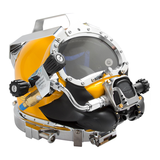
- Page 16 Defog free flow valve knob Helmet shell Sideblock EGS valve Equalization device Regulator adjustment knob Non-return valve Purge button Pull pin The Kirby Morgan 17C helmet ™ 140204001 © ⅯⅯⅩⅣ Kirby Morgan Dive Systems, Inc. All rights reserved. Document #...
-
Page 17: Chapter 1 General Information Kmdsi Products
They are not the part number. Next to the exploded drawing is a list of the “location” numbers that match the Kirby Morgan part num- bers along with the name of the part. Always check the part number when ordering to make sure it is correct. -
Page 18: 1�2 Full-Face Masks And Manifolds
2) no comfort insert is required on the 28 3) the face ports for the 18 and the 28 differ slightly in size. Both the KMB 18 and KMB 28 are approved. 140204001 © ⅯⅯⅩⅣ Kirby Morgan Dive Systems, Inc. All rights reserved. Document #... - Page 19 (tender) and one or more surface-supported divers, recompres- sion chambers, or other submersible systems. ™ SuperMask M-48 ™ marked w/ Rebreather pod 140204001 © ⅯⅯⅩⅣ Kirby Morgan Dive Systems, Inc. All rights reserved. Document #...
-
Page 20: 1�3 Kirby Morgan Diving Helmets
SuperLite 17A/B Kirby Morgan ® ® ™ approved and marked approved and marked ™ ™ Yoke and Latch Catch Neck Pad and Assembly Sealed Pull Pins. 140204001 © ⅯⅯⅩⅣ Kirby Morgan Dive Systems, Inc. All rights reserved. Document #... - Page 21 In all other respects, this tube adjustable demand regulator. The helmet is helmet is nearly identical to the Kirby Morgan 37. available in the umbilical over the shoulder, “B” configuration only. 140204001 © ⅯⅯⅩⅣ Kirby Morgan Dive Systems, Inc. All rights reserved. Document #...
- Page 22 All helmets and suits can leak water under certain conditions. Divers should use extreme caution when diving in contaminated waters. 140204001 © ⅯⅯⅩⅣ Kirby Morgan Dive Systems, Inc. All rights reserved. Document #...
- Page 23 • Rugged helmet shell and other components • No refinishing required if the surface is scratched or gouged • Elimination of threaded inserts for securing port retainer to helmet shell 140204001 © ⅯⅯⅩⅣ Kirby Morgan Dive Systems, Inc. All rights reserved. Document #...
-
Page 25: Chapter 2 Description & Operational Specifications Superlite
Kirby Morgan helmets are in- tended for professional use only and are not intended for recreation use by persons not trained in surface supplied procedures and practices. - Page 26 Whiskers™ are made This low-pressure area lowers the work of breathing and of a chemical resistant compound and are quite robust. adds another barrier to water leaking in. 140204001 © ⅯⅯⅩⅣ Kirby Morgan Dive Systems, Inc. All rights reserved. Document #...
-
Page 27: Notified Body
(127.4 BL/min) to the side block assembly at depth. -Temperature limitations: Use at water temperatures below 36º F requires use of hot water shroud and hot water. 140204001 © ⅯⅯⅩⅣ Kirby Morgan Dive Systems, Inc. All rights reserved. Document #... -
Page 28: 2�7 Helmet Features
O-ring seals to) which protects the neck ring and neck dam from side impact damage during the dive. 5) The neck dam design (latex and neoprene) has been changed to help position the helmet correctly 140204001 © ⅯⅯⅩⅣ Kirby Morgan Dive Systems, Inc. All rights reserved. Document #... - Page 29 Tie wrap Whisker exhaust Exhaust body valve insert Water dump valve Exhaust valve Kidney Starboard whisker wing plate O-ring Exhaust valve Quad exhaust Regulator body O-ring cover 140204001 © ⅯⅯⅩⅣ Kirby Morgan Dive Systems, Inc. All rights reserved. Document #...
- Page 30 Assembly any model of commercial diving helmet, under controlled conditions, that they have not previously used or trained in prior to use on the job. 140204001 © ⅯⅯⅩⅣ Kirby Morgan Dive Systems, Inc. All rights reserved. Document #...
-
Page 31: 2�9 Design Purpose
The KMACS-5 has specially designed high pressure regulators that re- duce high pressure air and provide an adequate flow to support divers to a depth of 130 FSW. 140204001 © ⅯⅯⅩⅣ Kirby Morgan Dive Systems, Inc. All rights reserved. Document #... - Page 32 The whisker deflects the exhaust bubbles away from the face port to keep the diver’s view clear. 140204001 © ⅯⅯⅩⅣ Kirby Morgan Dive Systems, Inc. All rights reserved. Document #...
- Page 33 The regulator adjustment knob should be adjusted to the easiest breathing setting at all times. Adjusting the regu- lator further in than necessary to keep from free-flowing increases breathing resistance. 140204001 © ⅯⅯⅩⅣ Kirby Morgan Dive Systems, Inc. All rights reserved. Document #...
-
Page 34: Emergency Gas Supply System (Egs)
EGS L.P hose and possible total loss of emergency supply gas in event of regulator failure. The KMDSI Restrictor Adaptor, KMDSI Part #555-210. 140204001 © ⅯⅯⅩⅣ Kirby Morgan Dive Systems, Inc. All rights reserved. Document #... -
Page 35: Helmet Attachment To The Diver
This system provides an extremely secure method of attaching the helmet to the diver. 140204001 © ⅯⅯⅩⅣ Kirby Morgan Dive Systems, Inc. All rights reserved. Document #... -
Page 36: Reducing Carbon Dioxide
O-rings at the factory. Fine sand or other substances that could interfere with the movement of the internal spring and shaft cannot 140204001 © ⅯⅯⅩⅣ Kirby Morgan Dive Systems, Inc. All rights reserved. Document #... -
Page 37: 2�12 Eye Protection For Welding
The hot water shroud can also be used as a sealed unit, filled with a hypersaline solution, when there is no continuous hot water supply available. Many 140204001 © ⅯⅯⅩⅣ Kirby Morgan Dive Systems, Inc. All rights reserved. Document #... -
Page 38: Helmet Transport And Storage
The helmets are sent to dealers by plane and truck. Depending on how the dealer wants it Packaging Step 3 sent. Packaging Step 4 Packaging Step 1 140204001 © ⅯⅯⅩⅣ Kirby Morgan Dive Systems, Inc. All rights reserved. Document #... -
Page 39: Helmet Carrying Bag
The KMDSI Helmet Bag, Part #500-901. The KMDSI bag is made from extra heavy duty, black, ripstop nylon. The bottom of the bag is pad- 140204001 © ⅯⅯⅩⅣ Kirby Morgan Dive Systems, Inc. All rights reserved. Document #... -
Page 41: Chapter 3 Operating Instructions
The umbilical is the diver’s lifeline to the diving Never dive without a qualified tender holding your control station. diving hose. 140204001 © ⅯⅯⅩⅣ Kirby Morgan Dive Systems, Inc. All rights reserved. Document #... - Page 42 See “Appendix 3 Table 3 SuperFlow / SuperFlow 350 Regulator ® ® High Pressure Regulated Source” on page 143 as a guide to supply pressure requirements. 140204001 © ⅯⅯⅩⅣ Kirby Morgan Dive Systems, Inc. All rights reserved. Document #...
-
Page 43: 3�3 First Use Of Your Kirby Morgan Diving Helmet
Note: For divers with smaller sized heads, install the in the proper fit of the oral nasal mask to the face. head cushion foam spacer before installing the head cushion into the helmet. 140204001 © ⅯⅯⅩⅣ Kirby Morgan Dive Systems, Inc. All rights reserved. Document #... -
Page 44: Foam Trimming Tips
The “egg shell” side of the Left & Right Side Foams The head cushion foam spacer (HCFS) is a simple usually faces outward against the Helmet Shell. length of foam that is nested into the head cushion. 140204001 © ⅯⅯⅩⅣ Kirby Morgan Dive Systems, Inc. All rights reserved. Document #... - Page 45 SuperLite ® Ear Hole Trim Template 140204001 © ⅯⅯⅩⅣ Kirby Morgan Dive Systems, Inc. All rights reserved. Document #...
-
Page 47: Installation Of Head Cushion Foam Spacer (Hcfs)
Velcro Strap around to the top of the head cushion and secure. Proper installation and alignment of the HCFS in the helmet. 140204001 © ⅯⅯⅩⅣ Kirby Morgan Dive Systems, Inc. All rights reserved. Document #... -
Page 48: Maintenance Of The Head Cushion Foam Spacer (Hcfs)
If you trim the neck dam too much it will be too loose and will leak. Trim the neck dam until it is snug, then stretch it before use. 140204001 © ⅯⅯⅩⅣ Kirby Morgan Dive Systems, Inc. All rights reserved. Document #... -
Page 49: Adjusting The Neck Pad
Washer Adjustment nut Teflon ® Washer Washer Locking collar Hinge bolt Washer Screw T-washer Neck pad Locking Collar components. 140204001 © ⅯⅯⅩⅣ Kirby Morgan Dive Systems, Inc. All rights reserved. Document #... -
Page 50: 3�5 Pre Dress-In Procedure
8) Inspect the sealed pull pin on each side of the helmet. They must engage and disengage properly. 140204001 © ⅯⅯⅩⅣ Kirby Morgan Dive Systems, Inc. All rights reserved. Document #... -
Page 51: 3�6 Preparing The Helmet For Diving
Shut off the defogger control knob and screw in the adjustment knob on the regula- tor all the way. 140204001 © ⅯⅯⅩⅣ Kirby Morgan Dive Systems, Inc. All rights reserved. Document #... -
Page 52: 3�7 Emergency Gas System (Egs)
(Part # 200-017). The relief must be adjusted to start lifting at approximately 20 p.s.i.g. 140204001 © ⅯⅯⅩⅣ Kirby Morgan Dive Systems, Inc. All rights reserved. Document #... - Page 53 However, KMDSI believes that this method poses the least amount of risk for the diver. Probably the most serious problem with any of the other possible configurations is that the first stage will 140204001 © ⅯⅯⅩⅣ Kirby Morgan Dive Systems, Inc. All rights reserved. Document #...
- Page 54 In this way, if you have a leak, you will probably figure it out and will be able to take appropriate action. 140204001 © ⅯⅯⅩⅣ Kirby Morgan Dive Systems, Inc. All rights reserved. Document #...
- Page 55 Disadvantages • Regulator will flood and need service daily • Two valves to open in * Requires ability to reach cylinder emergency valve without difficulty 140204001 © ⅯⅯⅩⅣ Kirby Morgan Dive Systems, Inc. All rights reserved. Document #...
- Page 56 EGS regulator and result- ing in possible injury or death. 140204001 © ⅯⅯⅩⅣ Kirby Morgan Dive Systems, Inc. All rights reserved. Document #...
-
Page 57: 3�8 Setting Up To Dive
Do not twist the connectors. Do not pull them apart Connecting the umbilical to the helmet. by pulling on the thin part of the wires. 140204001 © ⅯⅯⅩⅣ Kirby Morgan Dive Systems, Inc. All rights reserved. Document #... -
Page 58: Opening The Breathing Gas Supply To The Helmet
It is impossible for the diver to see whether he is properly dressed in once the helmet is on his head. 140204001 © ⅯⅯⅩⅣ Kirby Morgan Dive Systems, Inc. All rights reserved. Document #... - Page 59 The locking collar/neck pad assembly must be open and hanging down behind your shoul- ders. 140204001 © ⅯⅯⅩⅣ Kirby Morgan Dive Systems, Inc. All rights reserved. Document #...
- Page 60 Push the neck dam/ring up into the neck ring on the base of the helmet. The sealed pull pins must be in the locking position. If they are in the open position, rotate until they snap 140204001 © ⅯⅯⅩⅣ Kirby Morgan Dive Systems, Inc. All rights reserved. Document #...
-
Page 61: Testing The Breathing System
Turn the supply gas off at the dive control system and bleed the umbilical. 140204001 © ⅯⅯⅩⅣ Kirby Morgan Dive Systems, Inc. All rights reserved. Document #... -
Page 62: 3�10 Diving Procedures
This adjustment device is not intended as a minimum- maximum device. Minimum and maximum applies to 140204001 © ⅯⅯⅩⅣ Kirby Morgan Dive Systems, Inc. All rights reserved. Document #... -
Page 63: 3�11 Emergency Procedures
If the demand regulator free flows, adjust the knob in If the flow is noticeably better, immediately notify (clockwise) until it stops. If the free flow cannot be 140204001 © ⅯⅯⅩⅣ Kirby Morgan Dive Systems, Inc. All rights reserved. Document #... -
Page 64: 3�12 Post Dive Procedures
The head cushion should be dried and replaced in the hat before storage. The regulator adjustment knob should be unscrewed all the way out (counterclockwise) until 140204001 © ⅯⅯⅩⅣ Kirby Morgan Dive Systems, Inc. All rights reserved. Document #... -
Page 67: Chapter 4 Troubleshooting
Troubleshooting 4.1 General Kirby Morgan diving helmets are highly reliable life support equipment which should not malfunction if proper preventative maintenance procedures are followed. Most problems encountered in using the helmet can be easily remedied. The following information covers most potential operating difficulties. -
Page 68: 4�4 Side Valve Malfunction
Clear cushion or dam under o-ring at neck dam. Regulator assembled improperly. Check for proper assembly. Damaged or loose reg pod. Tighten/ repair pod Damaged gasket Replace gasket 140204001 © ⅯⅯⅩⅣ Kirby Morgan Dive Systems, Inc. All rights reserved. Document #... -
Page 69: 4�6 Demand Regulator Malfunction
Service regulator. Knob difficult to turn. Stem bent. Replace stem. Valve will not flow gas. Foreign matter in valve. Disassemble, clean, and reassemble. Stripped control knob. Replace knob. 140204001 © ⅯⅯⅩⅣ Kirby Morgan Dive Systems, Inc. All rights reserved. Document #... -
Page 71: Chapter 5 Inspection And Maintenance
The daily and monthly inspections will determine The checklist can be laminated placed on a clipboard the necessity for overhaul with greater accuracy than and checked off with a grease pencil. Completion 140204001 © ⅯⅯⅩⅣ Kirby Morgan Dive Systems, Inc. All rights reserved. Document #... - Page 72 The checklist’s are intended to be used for all models of KMDSI SuperLite and KM Helmets and band ® masks. All KMDSI helmet and band mask manuals can be downloaded free at www.kirbymorgan.com. 140204001 © ⅯⅯⅩⅣ Kirby Morgan Dive Systems, Inc. All rights reserved. Document #...
-
Page 73: Chapter 6 General Preventative Maintenance
Tools required to do proper maintenance on the SL‑17C. Torque wrench with the following attachments: 1 3/8 inch crows foot 7/ 1 6 inch open end wrench 140204001 © ⅯⅯⅩⅣ Kirby Morgan Dive Systems, Inc. All rights reserved. Document #... -
Page 74: Component And Parts Cleaning
Dow-Corning 111 or equivalent. ® Do not use aerosol spray or lubricants. Many aero- sol propellants will damage plastic. Avoid lubricant contact with plastic parts. 140204001 © ⅯⅯⅩⅣ Kirby Morgan Dive Systems, Inc. All rights reserved. Document #... -
Page 75: Teflon Tape
Using the helmet in sea water while jetting in sand of more than 1½ wraps could cause excess Teflon ® will necessitate increased maintenance. Use of the tape to travel into the breathing system. 140204001 © ⅯⅯⅩⅣ Kirby Morgan Dive Systems, Inc. All rights reserved. Document #... -
Page 76: O-Ring Removal/Inspection/Cleaning And Lubrication
Replace O-rings if any damage is found or suspected. 140204001 © ⅯⅯⅩⅣ Kirby Morgan Dive Systems, Inc. All rights reserved. Document #... -
Page 77: General Cleaning Guidelines
Sanitizing of the oral-nasal mask/regulator of SL-17C is accomplished using one of four approved germi- cidal cleansing solutions. There are four examples 140204001 © ⅯⅯⅩⅣ Kirby Morgan Dive Systems, Inc. All rights reserved. Document #... -
Page 78: Daily Maintenance
140204001 © ⅯⅯⅩⅣ Kirby Morgan Dive Systems, Inc. All rights reserved. Document #... -
Page 79: 6�5 Monthly Maintenance (Or Between Jobs)
9) Rinse the neck dam assembly and allow to dry. Remove the O-ring from the neck dam ring, clean and lubricate. 10) If the neck dam is damaged it should be replaced. 140204001 © ⅯⅯⅩⅣ Kirby Morgan Dive Systems, Inc. All rights reserved. Document #... -
Page 80: Head Cushion And Chin Cushion
O-rings and nose block shaft. Re- tighten the nut just to the point where the nose block device will still slide, but requires a firm push or pull. 140204001 © ⅯⅯⅩⅣ Kirby Morgan Dive Systems, Inc. All rights reserved. Document #... -
Page 81: 6�6 Inspect The Exhaust Valve
Exhaust body valve insert Water dump valve Exhaust valve Kidney Starboard whisker wing plate O-ring Exhaust valve Quad exhaust Regulator body O-ring cover The Quad‑Valve™ Exhaust System 140204001 © ⅯⅯⅩⅣ Kirby Morgan Dive Systems, Inc. All rights reserved. Document #... -
Page 83: Chapter 7 Breathing System Maintenance And Repairs
2) After the one way valve has been removed, use two wrenches or hold the hex part of the body in a soft jaw vise while removing the seat with a wrench. 140204001 © ⅯⅯⅩⅣ Kirby Morgan Dive Systems, Inc. All rights reserved. Document #... -
Page 84: Reassembly Of The One Way Valve
1) Slide the new O-ring over the poppet. 2) Insert the new spring into the valve body, followed by the poppet. Tighten to "150" inch lbs. ("17" Newton Meters) with a torque wrench. 140204001 © ⅯⅯⅩⅣ Kirby Morgan Dive Systems, Inc. All rights reserved. Document #... -
Page 85: 7�3 Side Block Assembly
NOTE: The alignment screw is located in a recess in regulator inlet nipple. the fiberglass next to the stud. This recess is normally 140204001 © ⅯⅯⅩⅣ Kirby Morgan Dive Systems, Inc. All rights reserved. Document #... -
Page 86: Side Block Assembly Replacement
Be sure to peel or scrape the 2) Fit the side block to the helmet shell. Components of the Side Block & Air Train Air Train Air Train Gasket 140204001 © ⅯⅯⅩⅣ Kirby Morgan Dive Systems, Inc. All rights reserved. Document #... - Page 87 Slip the air train over the stud. Align the air chemical is an irritant train with the upper edge of the view port opening and may cause tissue in the helmet shell. damage. 140204001 © ⅯⅯⅩⅣ Kirby Morgan Dive Systems, Inc. All rights reserved. Document #...
-
Page 88: 7�4 Defogger Valve
The valve stem usually comes out with the bonnet. Clean all the metal parts to remove salts. The seat should be removed for inspection. 140204001 © ⅯⅯⅩⅣ Kirby Morgan Dive Systems, Inc. All rights reserved. Document #... -
Page 89: Reassembly Of The Defogger Valve
3) Insert the proper end of the stem into the seat assembly and turn clockwise until the seat lightly bottoms out. Leave the stem in place. 140204001 © ⅯⅯⅩⅣ Kirby Morgan Dive Systems, Inc. All rights reserved. Document #... -
Page 90: Disassembly Of The Emergency Valve
Remove the lock nut, spring and knob. smooth and free of corrosion or damage. Undo the packing nut. Inspect the packing and washer. 140204001 © ⅯⅯⅩⅣ Kirby Morgan Dive Systems, Inc. All rights reserved. Document #... -
Page 91: Reassembly Of Emergency Valve
(525-311), for rebuild- ing both the older style and the newer high flow Valve Body Packing Knob Lock nut Valve Stem Washer Packing nut Spring The emergency valve 140204001 © ⅯⅯⅩⅣ Kirby Morgan Dive Systems, Inc. All rights reserved. Document #... -
Page 92: Leak Testing The Egs Valve
1/4” NPT tap to obtain the proper make should always be used with the EGS up. If thread chasing is required, the bent tube assembly, system to help minimize this risk. 140204001 © ⅯⅯⅩⅣ Kirby Morgan Dive Systems, Inc. All rights reserved. Document #... -
Page 93: 7�6 Bent Tube Assembly
If the tube fails, this could lead to a rapid depletion of the diver’s breathing gas supply. This could lead to serious personal injury or death. Loosening the jam nut. 140204001 © ⅯⅯⅩⅣ Kirby Morgan Dive Systems, Inc. All rights reserved. Document #... -
Page 94: Installation Of The Bent Tube Assembly
6) Hold the mount nut on the end of the bent tube with a wrench and tighten the jam nut against it with a torque wrench to "40" inch pounds. 140204001 © ⅯⅯⅩⅣ Kirby Morgan Dive Systems, Inc. All rights reserved. Document #... -
Page 95: Demand Regulator
1/16” and 1/8” free travel in the button before gas flow starts. When the button is fully de- pressed, a strong surge of gas must be heard. Tool Kit with pouch - Part #525-620. 140204001 © ⅯⅯⅩⅣ Kirby Morgan Dive Systems, Inc. All rights reserved. Document #... -
Page 96: Inspection Of Superflow ® 350 Regulator Body Interior
This can lead to fatigue and the inability to work at full capacity. 140204001 © ⅯⅯⅩⅣ Kirby Morgan Dive Systems, Inc. All rights reserved. Document #... -
Page 97: Reassembly Of The Superflow ® 350 Regulator Adjustment System
Use the inlet valve holder from the NOTE: Carefully inspect the adjustment shaft to regulator tool kit to accurately align these holes. ensure it is straight, Check for damaged threads. 140204001 © ⅯⅯⅩⅣ Kirby Morgan Dive Systems, Inc. All rights reserved. Document #... -
Page 98: Superflow ® 350 Demand Regulator Removal From Helmet
Torque Wrench and 11/16 Open-end Attachment the helmet. Torque Wrench and 13/16 Open-end Attachment Torque Wrench and 7/8 inch Open-end Attachment The regulator mount nut must be removed to remove the regulator. 140204001 © ⅯⅯⅩⅣ Kirby Morgan Dive Systems, Inc. All rights reserved. Document #... -
Page 99: Disassembly Of The Superflow ® 350 Demand Regulator
Spacer Regulator Packing Piston body Gasket Diaphragm Inlet valve Clamp Inlet nipple Spacer Exhaust Cover valve Roller lever Exhaust Flange Washer The SuperFlow 350 regulator assembly. ® 140204001 © ⅯⅯⅩⅣ Kirby Morgan Dive Systems, Inc. All rights reserved. Document #... -
Page 100: Inspection Of Superflow ® 350 Demand Regulator Parts
NEVER lubricate the maintain proper adjustment. valve. Lubricating the valve can allow dirt to stick to the seat causing poor performance and wet breathing. 140204001 © ⅯⅯⅩⅣ Kirby Morgan Dive Systems, Inc. All rights reserved. Document #... -
Page 101: Reassembly Of The Superflow ® 350 Demand Regulator
They can also cause long term dam- age to body tissue. Read and follow all precautions listed on the silicone seal- ant tube and Material Safety Data Sheet. 140204001 © ⅯⅯⅩⅣ Kirby Morgan Dive Systems, Inc. All rights reserved. Document #... - Page 102 The exhaust valve is installed on the outside of the flange. The screws that hold the flange on the regulator body should be tightened to "6" inch pounds. 140204001 © ⅯⅯⅩⅣ Kirby Morgan Dive Systems, Inc. All rights reserved. Document #...
- Page 103 Regulator body Valve seat Inlet Nipple Spacer Roller lever Inlet valve Jam nut Washer SuperFlow 350 regulator body with roller lever assembly and inlet valve. ® 140204001 © ⅯⅯⅩⅣ Kirby Morgan Dive Systems, Inc. All rights reserved. Document #...
- Page 104 Packing nut Retaining Pin Shaft Spacer Piston Adjustment knob Spring set Regulator body Adjustment end of the SuperFlow 350 regulator. ® 140204001 © ⅯⅯⅩⅣ Kirby Morgan Dive Systems, Inc. All rights reserved. Document #...
- Page 105 This fine-tune the adjustment if necessary. will ensure the nut is bottomed on the shoulder on the bent tube. Do not tighten further. 140204001 © ⅯⅯⅩⅣ Kirby Morgan Dive Systems, Inc. All rights reserved. Document #...
-
Page 106: Tuning The Superflow ® 350 Regulator
If a slight flow of gas develops with the purge button depressed less than 1/ 1 6 inch (1.5 mm) the lever will require bending down. 140204001 © ⅯⅯⅩⅣ Kirby Morgan Dive Systems, Inc. All rights reserved. Document #... - Page 107 The legs of the lever must be properly aligned in the same plane. If one leg is up and the other is down, the regulator will not perform properly. 140204001 © ⅯⅯⅩⅣ Kirby Morgan Dive Systems, Inc. All rights reserved. Document #...
-
Page 108: Superflow ® 350 Regulator Steady Flows When Pressured Up: Special Tools Used
Repeat this procedure until the gas flow stops. proper flow rates. Usually at this point the regulator adjustment knob will be between 5 and 7 turns out. Note: If when 140204001 © ⅯⅯⅩⅣ Kirby Morgan Dive Systems, Inc. All rights reserved. Document #... - Page 109 If the regulator free flow did not stop after this procedure, refer to regulator disassembly and clean- ing sections of this manual. 140204001 © ⅯⅯⅩⅣ Kirby Morgan Dive Systems, Inc. All rights reserved. Document #...
-
Page 110: 7�8 Oral/Nasal
1) Remove the nose block device first. See chapter 8. 2) Remove the microphone. 3) The oral/nasal mask can then be pulled off the regulator mount nut. It is held on by a snap fit. 140204001 © ⅯⅯⅩⅣ Kirby Morgan Dive Systems, Inc. All rights reserved. Document #... -
Page 111: Oral/Nasal Replacement
This could lead to exhaustion and black- out resulting in serious injury or death. WRONG Correct Correct installation of the oral nasal valve is extremely important to your safety. 140204001 © ⅯⅯⅩⅣ Kirby Morgan Dive Systems, Inc. All rights reserved. Document #... -
Page 112: 7�9 Quad-Valve™ Exhaust Assembly
Whisker clamp Port whisker Tie wrap Whisker exhaust Exhaust body valve insert Water dump valve Exhaust valve Starboard whisker O-ring Quad exhaust cover Exploded view of the Quad-Valve™ exhaust system. 140204001 © ⅯⅯⅩⅣ Kirby Morgan Dive Systems, Inc. All rights reserved. Document #... -
Page 113: Quad-Valve™ Exhaust Valves
The exhaust valve inserts are recessed on one side to accept the exhaust valves so they sit flush in the inserts. The exhaust valves must be installed properly in the inserts or they will not seal or perform properly. 140204001 © ⅯⅯⅩⅣ Kirby Morgan Dive Systems, Inc. All rights reserved. Document #... -
Page 114: Superflow ® 350 Regulator Exhaust Valve Replacement
Cut off the excess tie wrap tail. 3) Reinstall the regulator/exhaust assembly on the helmet. The whiskers must be aligned properly on the exhaust main body. 140204001 © ⅯⅯⅩⅣ Kirby Morgan Dive Systems, Inc. All rights reserved. Document #... -
Page 115: 7�10 Water Dump Exhaust Body
Read and follow all with the operation of the rubber exhaust valve. precautions listed on the silicone seal- ant tube and Material Safety Data Sheet. 140204001 © ⅯⅯⅩⅣ Kirby Morgan Dive Systems, Inc. All rights reserved. Document #... - Page 116 Addi- tionally, any substitutions will void all warranties offered by KMDSI. The Quad-Valve™ exhaust cover must be properly fastened to the main helmet exhaust. 140204001 © ⅯⅯⅩⅣ Kirby Morgan Dive Systems, Inc. All rights reserved. Document #...
-
Page 117: Chapter 8 Corrective Maintenance
This could be fatal. glass and insert repairs should be only be completed by technicians specifically trained and certified in Kirby Morgan repair procedures. 140204001 © ⅯⅯⅩⅣ Kirby Morgan Dive Systems, Inc. All rights reserved. Document #... -
Page 118: 8�2 Helmet Shell Inspection
24 hours before using helmet. Nose block device Oral/nasal mask O-ring Port retainer Knob Helmet shell Lens Packing nut Blowapart drawing of the nose block device and supporting hardware. 140204001 © ⅯⅯⅩⅣ Kirby Morgan Dive Systems, Inc. All rights reserved. Document #... -
Page 119: Nose Block Device Replacement
5) Tighten the knob with the pliers, padded by a cloth, while holding the pad end with your hand. Install the nose block device through the interior of the oral nasal mask. 140204001 © ⅯⅯⅩⅣ Kirby Morgan Dive Systems, Inc. All rights reserved. Document #... -
Page 120: 8�4 Handle And Weights
Use only wooden wedges under the corner edges of the weights. Remove the screw at the rear of the handle. 140204001 © ⅯⅯⅩⅣ Kirby Morgan Dive Systems, Inc. All rights reserved. Document #... - Page 121 DO NOT USE A SCREWDRIVER OR CHISEL TO REMOVE THE WEIGHT. This could damage the helmet shell, requiring expensive repair. 140204001 © ⅯⅯⅩⅣ Kirby Morgan Dive Systems, Inc. All rights reserved. Document #...
-
Page 122: Side Weight Removal
This chemical is an irri- Apply silicone to the interior view of the port weight as tant and may cause indicated by the white lines. tissue damage. 140204001 © ⅯⅯⅩⅣ Kirby Morgan Dive Systems, Inc. All rights reserved. Document #... -
Page 123: Top Weight
Avoid skin contact with acetone. Wear the hole, but do not tighten them yet. rubber gloves. Acetone can damage the nervous system. 140204001 © ⅯⅯⅩⅣ Kirby Morgan Dive Systems, Inc. All rights reserved. Document #... -
Page 124: 8�5 Face Port
1) First remove the nose block device knob then the packing nut and slip the O-rings off the nose block shaft. Remove the port retainer. Remove the port retainer screws. 140204001 © ⅯⅯⅩⅣ Kirby Morgan Dive Systems, Inc. All rights reserved. Document #... - Page 125 SuperLite ® Don't misplace the small o-ring on the back of the port retainer. Clean the O-ring groove. 140204001 © ⅯⅯⅩⅣ Kirby Morgan Dive Systems, Inc. All rights reserved. Document #...
-
Page 126: Face Port And Nose Block Replacement
KMDSI recommended torque specs be followed replacing. Replacement of inserts should only be 140204001 © ⅯⅯⅩⅣ Kirby Morgan Dive Systems, Inc. All rights reserved. Document #... -
Page 127: Special Note Regarding Ports
Im- proper application of cleaning agents may cause the port to fail without warn- ing. This could lead to drowning. 140204001 © ⅯⅯⅩⅣ Kirby Morgan Dive Systems, Inc. All rights reserved. Document #... -
Page 128: Removal Of The Neck Dam
4) Separate the split neck dam rings and neck dam from the stepped ring. O-ring Neck Stepped Ring Split Ring Front Yoke Pull Screw Strap Blowapart drawing of neck dam assembly for SuperLite 17C helmet. ® 140204001 © ⅯⅯⅩⅣ Kirby Morgan Dive Systems, Inc. All rights reserved. Document #... -
Page 129: Latex Neck Dam Replacement
7) Tighten the screws to "10" inch lbs ("1.1" Newton Meters) of torque. Center the split rings by pressing on the dam and feeling the inside edge of the stepped ring and the split rings. 140204001 © ⅯⅯⅩⅣ Kirby Morgan Dive Systems, Inc. All rights reserved. Document #... -
Page 130: Trimming A Latex Neck Seal
This could allow water to enter sure on the carotid artery in the neck. the helmet and drowning could result. This could lead to severe personal injury or death. 140204001 © ⅯⅯⅩⅣ Kirby Morgan Dive Systems, Inc. All rights reserved. Document #... -
Page 131: 8�7 Pull Strap
2) Screw the two screws through the strap plate until the heads of the screws bottom out against the strap Snap plate. Do not overtighten. Screw Washer Chin strap The chin strap mounts inside the helmet. 140204001 © ⅯⅯⅩⅣ Kirby Morgan Dive Systems, Inc. All rights reserved. Document #... -
Page 132: O-Ring Seal Replacement
O-rings manufactured by other vendors. This O-ring must be replaced with a KMDSI O-ring. Failure to do so could lead to seal failure. This could lead to drowning. 140204001 © ⅯⅯⅩⅣ Kirby Morgan Dive Systems, Inc. All rights reserved. Document #... -
Page 133: 8�10 Helmet Ring
The strike angle must be correct for the pins to work KMDSI recommends that these pins be serviced properly. annually. Your KMDSI dealer can provide you with either new pins (Part # 505-110) or factory refur- 140204001 © ⅯⅯⅩⅣ Kirby Morgan Dive Systems, Inc. All rights reserved. Document #... -
Page 134: 8�12 Swing Tongue Catch
Run the screw in until it is just snug. 3) Remove the screw from the left side of the swing tongue catch. Spring Spacer Spring spacer Swing Catch Diagram of the swing tongue catch. 140204001 © ⅯⅯⅩⅣ Kirby Morgan Dive Systems, Inc. All rights reserved. Document #... - Page 135 6) Tighten all three screws to "20" inch pounds ("2.25" Newton Meters.) of torque. Make sure you have not dislodged the Teflon washer. ® 140204001 © ⅯⅯⅩⅣ Kirby Morgan Dive Systems, Inc. All rights reserved. Document #...
-
Page 136: 8�13 Locking Collar/Neck Pad
4) Clean all parts that will be reused. Loosen the bolt to remove it from the hinge. Take care not to lose the Teflon washers ® 140204001 © ⅯⅯⅩⅣ Kirby Morgan Dive Systems, Inc. All rights reserved. Document #... -
Page 137: Locking Collar Disassembly
3) Slide the neck pad off the locking collar. Washer Adjustment nut Teflon ® Washer Washer Locking collar Hinge bolt Washer Screw T-washer Neck pad Exploded view of the locking collar assembly. 140204001 © ⅯⅯⅩⅣ Kirby Morgan Dive Systems, Inc. All rights reserved. Document #... -
Page 138: Locking Collar Reassembly
8) Slide one of the Teflon washers between the lock- ® ing collar and hinge block on the rear of the helmet ring. 140204001 © ⅯⅯⅩⅣ Kirby Morgan Dive Systems, Inc. All rights reserved. Document #... - Page 139 13) Tighten the nut to until the bolt just protrudes past Teflon washer and the locking collar until it protrudes the end of the nylock insert. ® from the locking collar. 140204001 © ⅯⅯⅩⅣ Kirby Morgan Dive Systems, Inc. All rights reserved. Document #...
-
Page 140: Head Cushion Foam
The diver’s head can be moved up or down in the The chin cushion. helmet by decreasing or increasing the foam pads at the top of the head cushion. 140204001 © ⅯⅯⅩⅣ Kirby Morgan Dive Systems, Inc. All rights reserved. Document #... -
Page 141: 8�15 Communications System
005 or 515-006. Inspect the mylar earphone. Earphone (left) Tie-Wrap Screw Earphone (right) Earphone Speaker Cover Protector Earphone Earphone Speaker Communication Cover Wire Microphone Earphone and microphone assemblies 140204001 © ⅯⅯⅩⅣ Kirby Morgan Dive Systems, Inc. All rights reserved. Document #... -
Page 142: Removal Of Communications Assembly
Save the inboard and outboard ferrules, and the packing nut. 140204001 © ⅯⅯⅩⅣ Kirby Morgan Dive Systems, Inc. All rights reserved. Document #... -
Page 143: Connector Replacement
8) Connect the wire lugs on the connector to the communications terminal block on the interior of the helmet. 140204001 © ⅯⅯⅩⅣ Kirby Morgan Dive Systems, Inc. All rights reserved. Document #... -
Page 145: Terminal Connections In The Waterproof Connector
2) Remove the defogger knob, locknut, and spring. 3) Remove the emergency valve knob, nut, and spring. 4) Screw the regulator adjustment knob in all the way. 140204001 © ⅯⅯⅩⅣ Kirby Morgan Dive Systems, Inc. All rights reserved. Document #... - Page 146 14) Trim the excess ends from the tie wraps. Slide one of the PVC pieces over the bent tube and insert it into the regulator shroud. Install the corrugated tube. 140204001 © ⅯⅯⅩⅣ Kirby Morgan Dive Systems, Inc. All rights reserved. Document #...
-
Page 147: Communications Posts
Pull the corrugated tube over the PVC flange at the The low pressure inflator system may be used with sideblock. Fasten the tie-wraps and trim the excess off the ends. 140204001 © ⅯⅯⅩⅣ Kirby Morgan Dive Systems, Inc. All rights reserved. Document #... -
Page 148: Installation Of The Low Pressure Inflator Hose
Adapter, P/N 555-210 must be used. Without a restrictor, a hose failure could deplete the Emergency Gas Supply very rapidly leading to suffocation. This could result in serious personal injury or death. 140204001 © ⅯⅯⅩⅣ Kirby Morgan Dive Systems, Inc. All rights reserved. Document #... -
Page 149: Weld Lens Assembly
Weld Lens Kit for installation of this as- sembly. Longer screws will damage the helmet shell and/or the threaded inserts. This could cause flooding through the port. 140204001 © ⅯⅯⅩⅣ Kirby Morgan Dive Systems, Inc. All rights reserved. Document #... -
Page 150: Weld Shield Assembly
KMDSI SuperFlow first stage regulator (or any high perfor- ® mance regulator) used for the bail-out supply. Weld Shield Assembly 140204001 © ⅯⅯⅩⅣ Kirby Morgan Dive Systems, Inc. All rights reserved. Document #... -
Page 151: Table Of Equivalents
Inches of Mercury (Hg) 2.036 Quarts Gallons 0.25 Square Feet Square Inches Temperature ( F - 32) Temperature ( 0.5555 Tons (U.S.) Pounds 2000 Watts Horsepower 0.001341 140204001 © ⅯⅯⅩⅣ Kirby Morgan Dive Systems, Inc. All rights reserved. Document #... -
Page 152: Appendix 1: Torque Specifications
See Note 1 Seat, One Way Valve Body, One Way Valve 555-195 One Way Valve 2.25 550-024 Stud, Side Block Loctite Loctite ® ® 550-020 Bonnet Defogger Valve 11.3 140204001 © ⅯⅯⅩⅣ Kirby Morgan Dive Systems, Inc. All rights reserved. Document #... -
Page 153: Note On Torque Specifications
Tighten pipe thread using good engineering practices. Two turns by ® hand, two turns by wrench. * For a neoprene neck dam, turn the screw three turns. Screws may need adjustment after several dives. 140204001 © ⅯⅯⅩⅣ Kirby Morgan Dive Systems, Inc. All rights reserved. Document #... - Page 154 O-rings and need for the stringent specialized oxygen clean post- 140204001 © ⅯⅯⅩⅣ Kirby Morgan Dive Systems, Inc. All rights reserved. Document #...
- Page 155 Persons mixing han- 235-2715 or E-mail them at divelab@aol.com. dling and working with breathing gases should be properly trained in all aspects of safe gas handling. 140204001 © ⅯⅯⅩⅣ Kirby Morgan Dive Systems, Inc. All rights reserved. Document #...
- Page 156 The increase in resistive effort can cause an increase in blood level CO because the diver cannot ventilate as freely as when breathing at the surface. When 140204001 © ⅯⅯⅩⅣ Kirby Morgan Dive Systems, Inc. All rights reserved. Document #...
-
Page 157: And Superflow
62.5 3.55 221.59 265.91 9.39 2.97 222.73 267.27 9.44 150 PSIG / 10.35 BAR 5.39 215.76 258.91 9.15 4.64 231.82 278.18 9.83 62.5 3.88 242.42 290.91 10.28 140204001 © ⅯⅯⅩⅣ Kirby Morgan Dive Systems, Inc. All rights reserved. Document #... - Page 158 13.65 4.27 320.45 384.55 13.58 220 PSIG / 15.18 BAR 7.67 306.67 368.00 13.00 6.52 325.76 390.91 13.81 62.5 5.45 340.91 409.09 14.45 4.36 327.27 392.73 13.87 140204001 © ⅯⅯⅩⅣ Kirby Morgan Dive Systems, Inc. All rights reserved. Document #...
-
Page 159: Old Method
101-132 (30-40) (9.3) 133-165 (40-50) (11.4) 166-220 (50-67) (15.5) For more information on determining supply pressure related information check the Dive Lab web site at www. divelab.com. 140204001 © ⅯⅯⅩⅣ Kirby Morgan Dive Systems, Inc. All rights reserved. Document #...
Need help?
Do you have a question about the SuperLite 17C Helmet and is the answer not in the manual?
Questions and answers