Table of Contents
Advertisement
UM2264
User manual
Getting started with the STEVAL-IDB007V1M SPBTLE-1S module
development kit
Introduction
®
®
The SPBTLE-1S module is a low power Bluetooth
smart system-on-chip, compliant with the Bluetooth
v4.2 specification and supporting master, slave and simultaneous master-and-slave roles.
The available kit is the STEVAL-IDB007V1M development platform (order code: STEVAL-IDB007V1M).
The STEVAL-IDB007V1M provides a set of hardware resources for a wide range of application
scenarios: sensor data (accelerometer, pressure and temperature sensor), remote control (buttons and
LEDs) and debug message management through USB virtual COM. Three power options are available
(USB only, battery only and external power supply plus USB) for high application development and
testing flexibility.
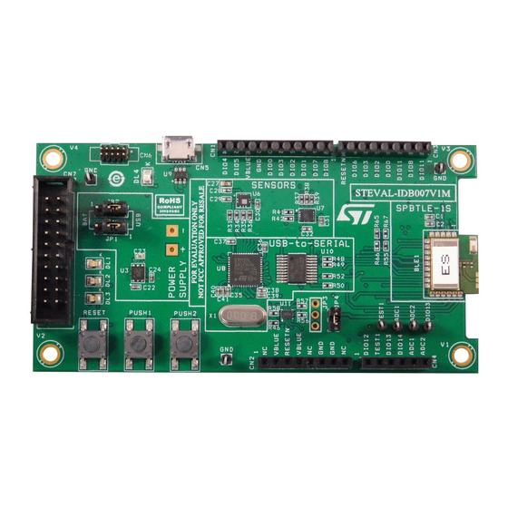
Figure 1: STEVAL-IDB007V1M development platform
July 2017
DocID030868 Rev 1
1/55
www.st.com
Advertisement
Table of Contents

Related Manuals for ST STEVAL-IDB007V1M SPBTLE-1S


Summary of Contents for ST STEVAL-IDB007V1M SPBTLE-1S
-
Page 1: Figure 1: Steval-Idb007V1M Development Platform
UM2264 User manual Getting started with the STEVAL-IDB007V1M SPBTLE-1S module development kit Introduction ® ® The SPBTLE-1S module is a low power Bluetooth smart system-on-chip, compliant with the Bluetooth v4.2 specification and supporting master, slave and simultaneous master-and-slave roles. The available kit is the STEVAL-IDB007V1M development platform (order code: STEVAL-IDB007V1M). -
Page 2: Table Of Contents
Contents UM2264 Contents Getting started ................. 7 Kit contents ..................7 System requirements ................ 7 BlueNRG-1 development kit setup ............ 7 Hardware description ..............8 STEVAL-IDB007V1M1 board overview ..........8 SPBTLE-1S module connections ............9 Power supply ................... 11 Jumpers ..................11 Sensors ................... - Page 3 UM2264 Contents Software directory structure ............24 BlueNRG-1 Beacon demonstration application ......25 BLE Beacon application setup ............25 6.1.1 Initialization ..................25 6.1.2 Define advertising data ..............25 6.1.3 Entering non-connectable mode ............25 BlueNRG-1 chat demo application ..........27 Peripheral and central device setup ..........
- Page 4 Contents UM2264 12.2 BLE HID/HOGP keyboard demonstration application ..... 38 BlueNRG-1 throughput demonstration application ....39 13.1 BLE unidirectional throughput scenario ........... 39 13.2 BLE bidirectional throughput scenario ..........39 BLE notification consumer demonstration application ....41 BlueNRG-1 peripheral driver examples ........42 15.1 ADC examples ................
- Page 5 UM2264 List of tables List of tables Table 1: STEVAL-IDB007V1M board component descriptions ..............9 Table 2: SPBTLE-1S module pin description with board functions ............9 Table 3: STEVAL-IDB007V1M kit platform power supply modes ............11 Table 4: STEVAL-IDB007V1M kit platform jumpers ................. 11 Table 5: BlueNRG-1 Beacon advertising manufacturing data ..............
- Page 6 Figure 21: BlueNRG sensor app ....................... 35 Figure 22: STEVAL-IDB007V1M Arduino connectors ................48 Figure 23: STEVAL-IDB007V1M JTAG ....................48 Figure 24: STEVAL-IDB007V1M SPBTLE-1S module (BlueNRG-1) ............49 Figure 25: STEVAL-IDB007V1M power management and sensors ............50 Figure 26: STEVAL-IDB007V1M buttons and LEDs ................51 Figure 27: STEVAL-IDB007V1M STM32 microprocessor ................
-
Page 7: Getting Started
Adobe Acrobat Reader 6.0 or later BlueNRG-1 development kit setup After downloading the BlueNRG-1 DK software package (STSW-BLUENRG1-DK) from www.st.com, extract BlueNRG-1_DK-x.x.x-Setup.zip contents to a temporary directory, launch BlueNRG-1-DK-x.x.x-Setup.exe and follow the on-screen instructions. EWARM Compiler 7.70 or later is required for building the BlueNRG1_DK_x.x.x demonstration applications. -
Page 8: Hardware Description
Hardware description UM2264 Hardware description STEVAL-IDB007V1M1 board overview The SPBTLE-1S module in the STEVAL-IDB007V1M development kit lets you experiment with BlueNRG-1 system-on-chip functions. It features: ® Bluetooth SMART board based on the BlueNRG-1 Bluetooth low energy system-on- chip Associated BlueNRG-1 development kit software package including firmware and documentation ... -
Page 9: Spbtle-1S Module Connections
UM2264 Hardware description Table 1: STEVAL-IDB007V1M board component descriptions Region Description SPBTLE-1S module Micro USB connector for power supply and I/O JTAG connector RESET button two USER buttons LPS25HB MEMS pressure sensor with embedded temperature LSM6DS3 3D digital accelerometer and 3D digital gyroscope PWR LED three user LEDs back of the... - Page 10 Hardware description UM2264 Board function Arduino connectors Pressure accelerometer name Micro Button JTAG sensor gyroscope pin 2 pin 6 DIO7 pin 7 pin 5 DIO6 pin 9 DIO5 PUSH2 button DIO4 pin 5 pin 6 DIO3 SDO/SA0 pin 4 pin 5 DIO2 pin 3 JTAG-...
-
Page 11: Power Supply
The board section labeled SPBTLE-1 (Figure 2: "STEVAL-IDB007V1M board components" – region A) includes only the certified and BQE qualified module SPBTLE-1S (for more details, see Figure 24: "STEVAL-IDB007V1M SPBTLE-1S module (BlueNRG-1)"). Power supply – region G) signals Green LED DL4 (Figure 2: "STEVAL-IDB007V1M board components"... -
Page 12: Extension Connector
The microcontroller is connected to the BlueNRG-1 device through an ST2378E level translator (region R). The STM32L microcontroller on the board is not intended to be programmed by users. ST provides a pre-programmed firmware image for the sole purpose of interfacing BlueNRG-1 to a USB host device (e.g., a PC). 2.11... -
Page 13: Hardware Setup
UM2264 Hardware description 2.12 Hardware setup Configure the board to USB power supply mode as per the jumper settings in Table 3: "STEVAL-IDB007V1M kit platform power supply modes" Connect the board to a PC via USB cable (connector CN5) Verify the power indication LED DL4 is on DocID030868 Rev 1 13/55... -
Page 14: Bluenrg-1 Navigator
BlueNRG-1 Navigator UM2264 BlueNRG-1 Navigator BlueNRG-1 Navigator is a user-friendly GUI which lets you select and run demonstration applications easily, without requiring any extra hardware. It lets you access the following BlueNRG-1 DK software package components: BlueNRG-1 Bluetooth low energy (BLE) demonstration applications ... -
Page 15: Figure 4: Ble Beacon Application
UM2264 BlueNRG-1 Navigator Flash: to automatically download and run the available prebuilt binary file to a BlueNRG-1 or SPBTLE-1S platform connected to a PC USB port. Doc: to display application documentation (html format) Project: to open the project folder with application headers, source and project files. The figure below shows you how to run the BLE Beacon demo application;... -
Page 16: Bluenrg-1 Navigator 'Basic Examples
BlueNRG-1 Navigator UM2264 Selecting the “Doc” tab opens the relative html documentation. Figure 6: BLE Beacon documentation BlueNRG-1 Navigator ‘Basic examples’ 3.1.1 This page lists some basic sample applications for the SPBTLE-1S or BlueNRG-1 device to verify that BlueNRG-1 device is alive as well as the device sleep and wakeup modes. Figure 7: Basic examples BlueNRG-1 Navigator ‘BLE demonstration and test applications’... -
Page 17: Bluenrg-1 Navigator 'Peripherals Driver Examples
UM2264 BlueNRG-1 Navigator Figure 8: BLE demonstration and test applications BlueNRG-1 Navigator ‘Peripherals driver examples’ 3.1.3 This page lists the available BlueNRG-1 peripherals and corresponding test applications to work with certain features specific to the selected SPBTLE-1S, based on BlueNRG-1, peripheral. -
Page 18: Bluenrg-1 Navigator 'Development Kits
BlueNRG-1 Navigator UM2264 BlueNRG-1 Navigator ‘Development Kits’ This window displays the available BlueNRG-1 DK Kit platforms and corresponding resources. When you hover the mouse pointer over a specific item, the related component is highlighted on the board. Figure 10: STEVAL-IDB007V1M Kit components BlueNRG-1 Navigator ‘Release Notes’... -
Page 19: Bluenrg-1 Flasher Utility
UM2264 BlueNRG-1 Flasher utility BlueNRG-1 Flasher utility The BlueNRG-1 Flasher utility allows SPBTLE-1S or BlueNRG-1 programming using the UART bootloader. How to run The BlueNRG-1 Flasher utility PC configuration requires the following minimum characteristics: ® ® a PC with USB port running Windows XP or Windows ... -
Page 20: Main User Interface Window
BlueNRG-1 Flasher utility UM2264 Main user interface window In the upper section of the BlueNRG-1 Flasher –Utility main window, you can: Select the image file (‘Select file’ button) Choose the flashing address (‘Flash from’ text input bar, only enabled for .bin files) Select the COM port to be used to interface the device (‘Port’... -
Page 21: Image File Selection
UM2264 BlueNRG-1 Flasher utility From the ‘Tools’ menu, you can mass erase all the device Flash memory. 4.2.2 Image file selection Use the ‘Select file’ button on the main page (or the File>Load menu) to load an existing .bin or .hex file. The full path of the selected file appears next to the button and the ‘Flash’ becomes active. -
Page 22: Using Bluenrg-1 Flasher Utility With Other Boards
BlueNRG-1 Flasher utility UM2264 Figure 15: BlueNRG-1 Flasher utility device memory viewer Click the ‘Read’ button to transfer the memory segment defined by ‘Start Address and ‘Size’ into the table. The first column gives the base address of the following 16 bytes in a row (e.g., row 0x10040050, column 4 holds the hexadecimal byte value at 0x10040054). -
Page 23: Figure 17: Bluenrg-1 Flasher Utility 'Comport Setting' Popup
UM2264 BlueNRG-1 Flasher utility Figure 17: BlueNRG-1 Flasher utility ‘Comport Setting’ popup When this popup appears, set the SPBTLE-1S or BlueNRG-1 pin DIO7 high and reset the SPBTLE-1S or BlueNRG-1 device (keeping the DIO7 high); the device should now be in bootloader mode. -
Page 24: Programming With Bluenrg-1 System-On-Chip
Programming with BlueNRG-1 system-on-chip UM2264 Programming with BlueNRG-1 system-on-chip The SPBTLE-1S module, based on BlueNRG-1 Bluetooth low energy (BLE) stack is provided as a binary library. A set of APIs to control BLE functionality. Some callbacks are also provided for user applications to handle BLE stack events. The user is simply requested to link this binary library to his or her application and use the relevant APIs to access BLE functions and complete the stack event callbacks to manage responses according to application requirements. -
Page 25: Bluenrg-1 Beacon Demonstration Application
UM2264 BlueNRG-1 Beacon demonstration application BlueNRG-1 Beacon demonstration application The BlueNRG-1 Beacon demo is supported by the SPBTLE-1S or BlueNRG-1 development platform (STEVAL-IDB007V1 or STEVAL-IDB007V1M). It demonstrates how to configure a SPBTLE-1S or BlueNRG-1 device to advertise specific manufacturing data and allow another BLE device to determine whether it is in BlueNRG-1 BLE Beacon device range. - Page 26 BlueNRG-1 Beacon demonstration application UM2264 /* Remove TX power level field from the advertising data: it is necessary have enough space for the beacon manufacturing data */ aci_gap_delete_ad_type(AD_TYPE_TX_POWER_LEVEL); /* Define the beacon manufacturing payload */ uint8_t manuf_data[] = {26, AD_TYPE_MANUFACTURER_SPECIFIC_DATA, 0x30, 0x00, //Company identifier code (Default is 0x0030 - STMicroelectronics) 0x02,// ID 0x15,//Length of the remaining payload...
-
Page 27: Bluenrg-1 Chat Demo Application
UM2264 BlueNRG-1 chat demo application BlueNRG-1 chat demo application The BlueNRG-1 chat demo (server and client roles) is supported on the SPBTLE-1S or BlueNRG-1 development platform (STEVAL-IDB007V1 or STEVAL-IDB007V1M). It implements simple two-way communication between two BlueNRG-1 devices, demonstrating point-to-point wireless communication using the BlueNRG-1 product. This demo application exposes a single chat service with the following (20 byte max.) characteristic values: ... -
Page 28: Add Service And Characteristics
BlueNRG-1 chat demo application UM2264 BLE Chat client role: aci_gap_init(GAP_CENTRAL_ROLE, 0, 0x08, &service_handle, &dev_name_char_handle, &appearance_char_handle); Peripheral and central BLE roles must be specified in the aci_gap_init() command. See the BlueNRG-1 BLE stack API documentation for more information on these and following commands. -
Page 29: Figure 18: Ble Chat Client
UM2264 BlueNRG-1 chat demo application on the BLE chat server device, the typed characters are sent to the BLE chat client device by notifying the previously added TX characteristic (after notifications are enabled) with: aci_gatt_update_char_value(chatServHandle,TXCharHandle,0,len, (uint8_t*)cmd+j); on the BLE chat client device, the typed characters are sent to the BLE chat server device by writing the previously added RX characteristic with: aci_gatt_write_without_resp(connection_handle, rx_handle+1, len, (uint8_t *)cmd+j);... -
Page 30: Ble Chat Master And Slave Demo Application
BLE chat master and slave demo application UM2264 BLE chat master and slave demo application The BlueNRG-1 chat master and slave demo is supported on the SPBTLE-1S or BlueNRG- 1 development platform (STEVAL-IDB007V1 or STEVAL-IDB007V1M). It demonstrates simple point-to-point wireless communication using a single application which configures the chat client and server roles at runtime. -
Page 31: Add Service And Characteristics
UM2264 BLE chat master and slave demo application The BLE peripheral and central roles are specified in the aci_gap_init() command. See the BlueNRG-1 BLE API documentation for more information on these and following commands. 8.1.2 Add service and characteristics Refer to Section 7.1.2: "Add service and characteristics". -
Page 32: Bluenrg-1 Remote Control Demo Application
BlueNRG-1 remote control demo application UM2264 BlueNRG-1 remote control demo application The BlueNRG-1 BLE remote control application is supported on the SPBTLE-1S or BlueNRG-1 development platforms (STEVAL-IDB007V1or STEVAL-IDB007V1M). It demonstrates how to control a remote device (like an actuator) using a BlueNRG-1 device. This application periodically broadcasts temperature values that can be read by any device. -
Page 33: Define Advertising Data
UM2264 BlueNRG-1 remote control demo application See BlueNRG-1 BLE stack API documentation for more information on these and following commands. 9.1.2 Define advertising data The BLE remote control application advertises certain manufacturing data as follows: /* Set advertising device name as Node */ const uint8_t scan_resp_data[] = {0x05,AD_TYPE_COMPLETE_LOCAL_NAME,'N','o','d','e'} /* Set scan response data */ hci_le_set_scan_response_data(sizeof(scan_resp_data),scan_resp_data);... -
Page 34: Bluenrg-1 Sensor Profile Demo
BlueNRG-1 sensor profile demo UM2264 BlueNRG-1 sensor profile demo The BlueNRG-1 sensor profile demo is supported on the BlueNRG-1 or SPBTLE-1S development platform (STEVAL-IDB007V1 or STEVAL-IDB007V1M). It implements a proprietary, Bluetooth low energy (BLE) sensor profile. This example is useful for building new profiles and applications that use the BlueNRG-1 SoC. -
Page 35: Bluenrg App For Smartphones
UM2264 BlueNRG-1 sensor profile demo 10.1 BlueNRG app for smartphones An application is available for iOS™ and Android™ smartphones or tablets that also works with the BLE sensor profile demo. This app enables notification of the acceleration characteristic and displays the value on screen. Data from environmental sensors are also periodically read and displayed. -
Page 36: Add Service And Characteristics
BlueNRG-1 sensor profile demo UM2264 10.2.2 Add service and characteristics The BlueNRG-1 BLE stack has both server and client capabilities. A characteristic is an element in the server database where data is exposed, while a service contains one or more characteristics. The acceleration service is added with the following command: aci_gatt_add_service(UUID_TYPE_128, &service_uuid, PRIMARY_SERVICE, 7, &accServHandle);... -
Page 37: Bluenrg-1 Sensor Profile Central Demo
UM2264 BlueNRG-1 sensor profile central demo BlueNRG-1 sensor profile central demo The BlueNRG-1 sensor profile central demo is supported on the BlueNRG-1 or SPBTLE- 1S development platforms (STEVAL-IDB007V1 or STEVAL-IDB007V1M). It implements a basic version of the BlueNRG-1 BLE Sensor Profile Central role which emulates the BlueNRG-1 Sensor Demo applications available for smartphones (iOS and Android). -
Page 38: Bluenrg-1 Hid/Hogp Demonstration Application
BlueNRG-1 HID/HOGP demonstration application UM2264 BlueNRG-1 HID/HOGP demonstration application The BLE HID/HOGP demonstration applications are supported by the BlueNRG-1 or SPBTLE-1S development platforms (STEVAL-IDB007V1 or STEVAL-IDB007V1M). It demonstrates a BlueNRG-1 device using the standard HID/HOGP Bluetooth low energy application profile. Keyboard and mouse demo examples are provided. 12.1 BLE HID/HOGP mouse demonstration application The BlueNRG-1 HID mouse application implements a basic HID mouse with two buttons... -
Page 39: Bluenrg-1 Throughput Demonstration Application
UM2264 BlueNRG-1 throughput demonstration application BlueNRG-1 throughput demonstration application The BlueNRG-1 throughput demonstration application provides some basic throughput demonstration applications to provide some reference figures regarding the achievable Bluetooth low energy data rate using the BlueNRG-1 device. The throughput application scenarios provided are: Unidirectional scenario: the server device sends characteristic notifications to a client device. - Page 40 BlueNRG-1 throughput demonstration application UM2264 Program the client bidirectional application on one BLE platform and reset it. The platform is seen on the PC as a virtual COM port. Open the related port in a serial terminal emulator (the required serial port baudrate is 921600) ...
-
Page 41: Ble Notification Consumer Demonstration Application
UM2264 BLE notification consumer demonstration application BLE notification consumer demonstration application The BLE ANCS demonstration application configures a BlueNRG-1 device or SPBTLE-1S module as a BLE notification consumer, which facilitates Bluetooth accessory access to the many notifications generated on a notification provider. After reset, the demo places the BlueNRG-1 device in advertising with device name "ANCSdemo"... -
Page 42: Bluenrg-1 Peripheral Driver Examples
BlueNRG-1 peripheral driver examples UM2264 BlueNRG-1 peripheral driver examples The BlueNRG-1 peripheral driver example applications are supported by the BlueNRG-1 or SPBTLE-1S development platform (STEVAL-IDB007V1 or STEVAL-IDB007V1M). The kit contains a set of examples demonstrating how to use the BlueNRG-1 device peripheral drivers (ADC, GPIOs, I²C, RTC, SPI, Timers, UART and WDG). -
Page 43: I²C Examples
UM2264 BlueNRG-1 peripheral driver examples IO wakeup: demonstrates device wakeup from standby mode using the GPIO interrupt. The PUSH1 button (IO13) is configured to generate the interrupt event on both edges of the input signal. LED DL2 is toggled, the system becomes active and LED DL1 is toggled by the systick interrupt service routine every 500 ms. -
Page 44: Rtc Examples
BlueNRG-1 peripheral driver examples UM2264 PUSH1: toggle LED DL1 15.5 RTC examples Clock watch: implements both RTC timer and RTC clockwatch. The RTC timer generates the 500 ms interrupt interval. The LED DL1 state is toggled in the RTC interrupt handler to signal proper RTC timer operation. The RTC clockwatch is also enabled with the system time and date set to December 1 2014, 23 h 59 m 31 s. -
Page 45: Systick Examples
UM2264 BlueNRG-1 peripheral driver examples The SPI is configured in master mode and the SPI clock set to 100 kHz. The data is transferred in the Motorola format with an 8-bit data frame, with clock low when inactive (CPOL=0) and data valid on clock trailing edge (CPHA = 1). Master DMA: SPI communication is controlled by DMA of the SPI status register content. - Page 46 BlueNRG-1 peripheral driver examples UM2264 Timer/Counter 1 interrupts on reload are enabled for MFTX1. Interrupt routines toggle LED DL1 for MFTX2. Mode 2 (dual-input capture mode): Timer/Counter 1 counts down with the selected clock and TnA and TnB pins function as capture inputs. Transitions received on the TnA and TnB pins trigger a transfer of timer content to the TnCRA and TnCRB registers, respectively.
-
Page 47: Uart Examples
UM2264 BlueNRG-1 peripheral driver examples MFT timers: this example shows how configure peripherals MFT1, MFT2 and SysTick to generate three timer interrupts at different rate: MFT1 at 500 ms, MFT2 at 250 ms and SysTick at 1 second. 15.9 UART examples DMA: IO8 and IO11 are configured as UART pins and DMA receive and transmit requests are enabled. -
Page 48: Schematic Diagrams
Schematic diagrams UM2264 Schematic diagrams Figure 22: STEVAL-IDB007V1M Arduino connectors Figure 23: STEVAL-IDB007V1M JTAG 48/55 DocID030868 Rev 1... -
Page 49: Figure 24: Steval-Idb007V1M Spbtle-1S Module (Bluenrg-1)
UM2264 Schematic diagrams Figure 24: STEVAL-IDB007V1M SPBTLE-1S module (BlueNRG-1) DocID030868 Rev 1 49/55... -
Page 50: Figure 25: Steval-Idb007V1M Power Management And Sensors
Schematic diagrams UM2264 Figure 25: STEVAL-IDB007V1M power management and sensors 50/55 DocID030868 Rev 1... -
Page 51: Figure 26: Steval-Idb007V1M Buttons And Leds
UM2264 Schematic diagrams Figure 26: STEVAL-IDB007V1M buttons and LEDs DocID030868 Rev 1 51/55... -
Page 52: Figure 27: Steval-Idb007V1M Stm32 Microprocessor
Schematic diagrams UM2264 Figure 27: STEVAL-IDB007V1M STM32 microprocessor 52/55 DocID030868 Rev 1... -
Page 53: Figure 28: Steval-Idb007V1M Usb, Level Translator, Jtag For Micro
UM2264 Schematic diagrams Figure 28: STEVAL-IDB007V1M USB, level translator, JTAG for micro Figure 29: STEVAL-IDB007V1M EEPROM/SWITCH DocID030868 Rev 1 53/55... -
Page 54: Revision History
Revision history UM2264 Revision history Table 8: Document revision history Date Version Changes 25-Jul-2017 Initial release. 54/55 DocID030868 Rev 1... - Page 55 ST products and/or to this document at any time without notice. Purchasers should obtain the latest relevant information on ST products before placing orders. ST products are sold pursuant to ST’s terms and conditions of sale in place at the time of order acknowledgement.
Need help?
Do you have a question about the STEVAL-IDB007V1M SPBTLE-1S and is the answer not in the manual?
Questions and answers