Table of Contents
Advertisement
Quick Links
UM1010
User manual
Getting started with the iNEMO™ STEVAL-MKI062V2
Introduction
The STEVAL-MKI062V2 is the second generation of the iNEMO modules family. It combines
accelerometers, gyroscopes, and magnetometers with pressure and temperature sensors to
provide 3-axis sensing of linear, angular, and magnetic motion, complemented with
temperature and barometer/altitude readings, representing the new ST 10-degrees of
freedom (DOF) platform.
This document provides a quick start guide for iNEMO PC software and graphical user
interface (GUI).
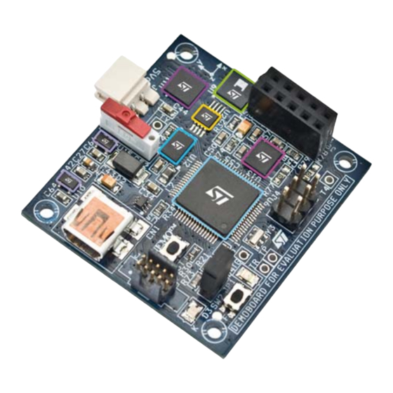
Figure 1.
STEVAL-MKI06V2 iNEMO V2 platform
October 2010
Doc ID 18054 Rev 1
1/18
www.st.com
www.BDTIC.com/ST
Advertisement
Table of Contents

Related Manuals for ST iNEMO STEVAL-MKI062V2 Series


Summary of Contents for ST iNEMO STEVAL-MKI062V2 Series
-
Page 1: Figure 1. Steval-Mki06V2 Inemo V2 Platform
3-axis sensing of linear, angular, and magnetic motion, complemented with temperature and barometer/altitude readings, representing the new ST 10-degrees of freedom (DOF) platform. This document provides a quick start guide for iNEMO PC software and graphical user interface (GUI). -
Page 2: Table Of Contents
Revision history ......... . . 17 2/18 Doc ID 18054 Rev 1 www.BDTIC.com/ST... - Page 3 Alignment procedure............16 Doc ID 18054 Rev 1 3/18 www.BDTIC.com/ST...
-
Page 4: Inemo V2 Gui Installation
To install the iNEMO suite, run the setup file and follow the instructions. Note: The latest setup file is available on st.com. Virtual Com driver installation To install the virtual COM driver, plug the iNEMO board into a free USB port, an icon should appear in the “Notify Bar”, as in... -
Page 5: Figure 3. Manual Installation Of The Steval-Mki062V2 Driver
UM1010 iNEMO V2 GUI installation Figure 3. Manual installation of the STEVAL-MKI062V2 driver Doc ID 18054 Rev 1 5/18 www.BDTIC.com/ST... -
Page 6: Figure 4. Inemo Driver Installation
V2 GUI installation UM1010 Figure 4. iNEMO driver installation Once the installation has finished, a COM port number is assigned to the ST virtual COM driver (Figure 5). Knowledge of this number is required to correctly run the iNEMO GUI. -
Page 7: Figure 5. How To See The Steval-Mki062V2 Com Port Number
UM1010 iNEMO V2 GUI installation Figure 5. How to see the STEVAL-MKI062V2 COM port number Doc ID 18054 Rev 1 7/18 www.BDTIC.com/ST... -
Page 8: Inemo Suite
GUI directly finds the COM port into which the board is plugged. To change COM port press the “New” button on the toolbar or from the menu File/New and the kit selector dialog appears. 8/18 Doc ID 18054 Rev 1 www.BDTIC.com/ST... -
Page 9: Inemo Suite Main Window
Toolbar for graphic management, helps the user to explore in the graphic window. It allows to zoom the graph, enabling cursors, save data, and so on Status bar shows the acquisition info Log window Default menu bar The graphical panel, where the data are graphically represented Doc ID 18054 Rev 1 9/18 www.BDTIC.com/ST... -
Page 10: Connecting Inemo
If the COM number is different, it is necessary to set the right number. By clicking the new data file icon (Figure 9) the kit selector window appears and it is possible to select the COM port number as in Figure 10/18 Doc ID 18054 Rev 1 www.BDTIC.com/ST... -
Page 11: Figure 9. New Data File Icon
When the correct COM number is set, click on the connect icon to open the communication and, in the log window, a connection message appears (Figure 10). Figure 10. How to open the connection Doc ID 18054 Rev 1 11/18 www.BDTIC.com/ST... -
Page 12: Acquisition Settings
By clicking the “Start” icon, the acquisition starts. The user can view the sensor data in the graphics. Each sensor is acquired simultaneously but it has a dedicated graphic, the user can choose the sensor by the icons on left of the GUI Figure 12/18 Doc ID 18054 Rev 1 www.BDTIC.com/ST... -
Page 13: Ahrs Algorithm Starting And Settings
If not, the user must strongly shake the board and, after that, leave the board in a motionless position waiting for flat data (sometimes it may be necessary to do this operation more than once). See Figure Doc ID 18054 Rev 1 13/18 www.BDTIC.com/ST... -
Page 14: Ahrs 3D Demo
It is also possible to start the application from the system menu Start/Programs/STMicroelectronics/iNEMO Suite/Demos/3D Cube Demo/ or launch from a console with the command “iNEMO 3D Cube Demo.exe IP=xxx.yyy.www.zzz, PORT=31001”, where xxx.yyy.www.zzz is the IP address where the server runs. 14/18 Doc ID 18054 Rev 1 www.BDTIC.com/ST... -
Page 15: 3D View Alignment
To align the iNEMO, it is necessary to point the USB cable towards the monitor and press the F2 key, if the calibration is correct, the cube shows the “goldfish” side (Figure 15). Doc ID 18054 Rev 1 15/18 www.BDTIC.com/ST... -
Page 16: Figure 15. Alignment Procedure
UM1010 Figure 15. Alignment procedure 16/18 Doc ID 18054 Rev 1 www.BDTIC.com/ST... -
Page 17: Revision History
UM1010 Revision history Revision history Table 1. Document revision history Date Revision Changes 11-Oct-2010 Initial release. Doc ID 18054 Rev 1 17/18 www.BDTIC.com/ST... - Page 18 No license, express or implied, by estoppel or otherwise, to any intellectual property rights is granted under this document. If any part of this document refers to any third party products or services it shall not be deemed a license grant by ST for the use of such third party products or services, or any intellectual property contained therein or considered as a warranty covering the use in any manner whatsoever of such third party products or services or any intellectual property contained therein.
Need help?
Do you have a question about the iNEMO STEVAL-MKI062V2 Series and is the answer not in the manual?
Questions and answers