Table of Contents
Advertisement
Quick Links
UM2901
User manual
Getting started with STEVAL-ISB68WTX for 2.5W TX application
Introduction
The STEVAL-ISB68WTX evaluation board based on
STWLC68JRF
designed for wireless power transmitter application.
STWLC68JRF
can deliver up to 2.5 W power to a Qi complaint wireless receiver.
Fully integrated
STWLC68JRF
require few external components for board design and can work with 5-20 V input power supply.
2
With External USB-to-I
C bridge, the user can monitor and control the
STWLC68JRF
chip with the STSW-ISB68PRO Graphical
User Interface (GUI).
The STEVAL-ISB68WTX includes several safety mechanisms providing over-temperature, over-current and over-voltage
protection as well as Foreign Object Detection (FOD).
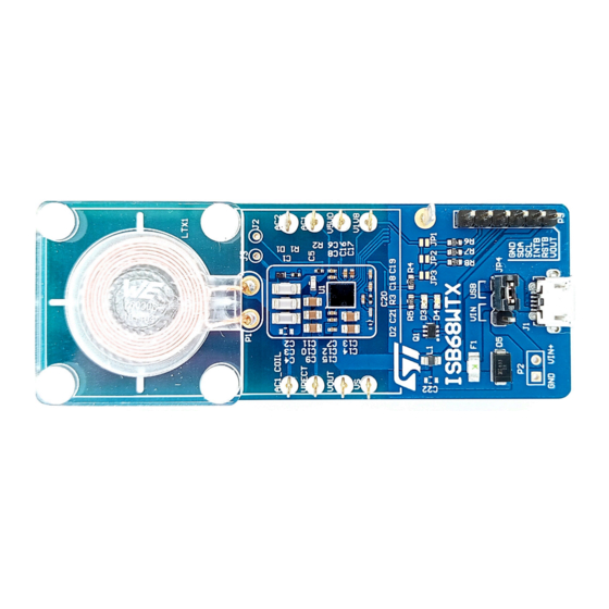
Figure 1.
STEVAL-ISB68WTX
UM2901 - Rev 1 - July 2021
www.st.com
For further information contact your local STMicroelectronics sales office.
Advertisement
Table of Contents

Related Manuals for ST STEVAL-ISB68WTX


Summary of Contents for ST STEVAL-ISB68WTX
-
Page 1: Figure 1. Steval-Isb68Wtx
C bridge, the user can monitor and control the STWLC68JRF chip with the STSW-ISB68PRO Graphical User Interface (GUI). The STEVAL-ISB68WTX includes several safety mechanisms providing over-temperature, over-current and over-voltage protection as well as Foreign Object Detection (FOD). Figure 1. STEVAL-ISB68WTX UM2901 - Rev 1 - July 2021 www.st.com... -
Page 2: Board Overview
UM2901 Board Overview Board Overview The STEVAL-ISB68WTX evaluation board default configuration is optimized for performance. The board features: • STWLC68JRFwireless power transmitter chip with up to 2.5 W output power capability • Low power applications with 5 V input voltage (supplied externally or USB adapter) •... -
Page 3: Board Configuration
Over Current Protection (OCP) at 2 A resulting in Tx Inverter output disconnection • Over Voltage Protection (OVP) at 10 V resulting in Tx inverter output disconnection Board configuration and test points The STEVAL-ISB68WTX has several connectors and test points to ease access to key signals. UM2901 - Rev 1 page 3/18... -
Page 4: Connection To Usb I 2 C Converter Board
Figure 2. Description of test points Figure 3. STEVAL-ISB68WTX layout Connection to USB I C converter board Connect external USB converter board to P3 connector, please ensure right connections for GND, SDA, SCL pins , as shown in below picture. -
Page 5: Usb To I 2 C Converter Board
UM2901 USB to I2C converter board Figure 4. STEVAL-ISB68WTX and USB-I C converter USB to I C converter board The USB to I C bridging dongle is the tool that allows interfacing the receiver to the Graphical User Interface running on a PC. -
Page 6: Board Power Supply
UM2901 Board power supply Board power supply The power to the board can be supplied using 5V/2A USB adapter, connected through J1 (microUSB receptacle) or using external 5V power source. Ensure a stable supply using high quality cables with minimal DC resistance for best overall efficiency. Board configuration The configuration settings of the STWLC68JRF... -
Page 7: Functional Description
UM2901 Functional description Functional description WPC Wireless charging system is shown in the below diagram. The TX is responsible for controlling the transmitting coil and generating the correct amount of power requested by the RX. The RX continuously provides the transmitter with the correct power level requested, by modulating the transmitter carrier through the controlled resistive or capacitive load. -
Page 8: Communication And Control
UM2901 Communication and control Figure 7. Power conversation Communication and control The 32-bit core MCU is the supervisor of the whole device and manages all the functional blocks to establish and maintain communication with the receiver. Ensure adherence to Qi standard specifications (wherever required), optimize the efficiency by properly adjusting the operating point and guarantee reliability by monitoring and protecting the device. -
Page 9: Fod
UM2901 Figure 8. ASK demodulation circuit STWLC68JRF has FOD detection feature. Any excess power loss in wireless power transfer can be monitored and the device can stop power transfer. The FOD detection is enabled by setting TX_FOD_EN bit to 1 in register 0x0021h. The AUTO FOD detection threshold can be set in AUTO_FOD_THR register 0x00EBh. -
Page 10: Component Layout
UM2901 Component Layout Component Layout Figure 9. Component layout UM2901 - Rev 1 page 10/18... -
Page 11: Schematic Of Steval-Isb68Wtx
UM2901 Schematic of STEVAL-ISB68WTX Schematic of STEVAL-ISB68WTX Schematic of STEVAL-ISB68WTX Figure 10. Schematic of STEVAL-ISB68WTX VRECT AC1_COIL VOUT V5V0 560R V5V0 V1V8 HE-RED HE-BLUE PGND AGND SGND GPIO0 GPIO1 ADC114YUQ SGND STWLC68 V1V8 BOOT BOOT COMM1 VRECT 100n VRECT VOUT_F... -
Page 12: Schematic Of Usb-I2C Board
UM2901 Schematic of USB-I2C board Schematic of USB-I2C board Figure 11. Schematic of USB-I2C board VBUS Littelfuse 0603L025 MCP_RSTB VBUS MCP_INTB I/O1 I/O1 MCP_INTB VBUS VUSB RSTB I/O2 I/O2 VBUS USBCL6-2 Shell Header connector STPS1L60ZFY Shield 470nF MicroUSB MCP2221 100nF GND GND RSTB VBUS... -
Page 13: Bill Of Material For 2.5 W Tx Application
UM2901 Bill of material for 2.5 W TX application Bill of material for 2.5 W TX application Table 1. Bill of material for 2.5W TX Component Value Manufacturer Part Number Notes C1, C2, C3, C4 100nF/50V Murata GCM155R71H104KE02D Series resonant capacitor 47nF/50V Murata GCM155R71H473KE02D... -
Page 14: Revision History
UM2901 Revision history Table 2. Document revision history Date Version Changes 14-Jul-2021 Initial release. UM2901 - Rev 1 page 14/18... -
Page 15: Table Of Contents
Schematic of STEVAL-ISB68WTX ........ -
Page 16: List Of Tables
UM2901 List of tables List of tables Table 1. Bill of material for 2.5W TX ............13 Table 2. -
Page 17: List Of Figures
Schematic of STEVAL-ISB68WTX........ - Page 18 ST’s terms and conditions of sale in place at the time of order acknowledgement. Purchasers are solely responsible for the choice, selection, and use of ST products and ST assumes no liability for application assistance or the design of Purchasers’...
Need help?
Do you have a question about the STEVAL-ISB68WTX and is the answer not in the manual?
Questions and answers