Table of Contents
Advertisement
Quick Links
Getting started with the STEVAL-STWINBX1 SensorTile wireless industrial node
Introduction
The STWIN.box (STEVAL-STWINBX1) is a development kit and reference design that simplifies prototyping and testing of
advanced industrial sensing applications in IoT contexts such as condition monitoring and predictive maintenance.
It is an evolution of the original STWIN kit (STEVAL-STWINKT1B) and features a higher mechanical accuracy in the
measurement of vibrations, an improved robustness, an updated BoM to reflect the latest and best-in-class MCU and industrial
sensors, and an easy-to-use interface for external add-ons.
The
STWIN.box
kit consists of an STWIN.box core system, a 480mAh LiPo battery, an adapter for the
plastic case, an adapter board for DIL 24 sensors and a flexible cable.
The many on-board industrial-grade sensors and the ultra-low power MCU enable applications that feature: ultra-low power,
9 DoF motion sensing, wide-bandwidth vibration analysis, audio and ultrasound acoustic inspection, very precise local
temperature, and environmental monitoring.
A rich set of software packages is available in source code. Optimized firmware libraries and a complete companion cloud
application help to speed up the design cycle to develop end-to-end solutions.
The kit supports a broad range of connectivity options, including the built-in RS485 transceiver, BLE, Wi-Fi, and NFC.
The
STWIN.box
also includes a 34-pin expansion connector for small form factor daughter boards associated with the STM32
family, such as the
STEVAL-C34KAT1
The
STWIN.box
is suitable for field trials, demonstrations, and PoC for industrial IoT applications that use ST software and
third-party software.
UM2965 - Rev 1 - December 2022
For further information contact your local STMicroelectronics sales office.
vibrometer and temperature sensors expansion board.
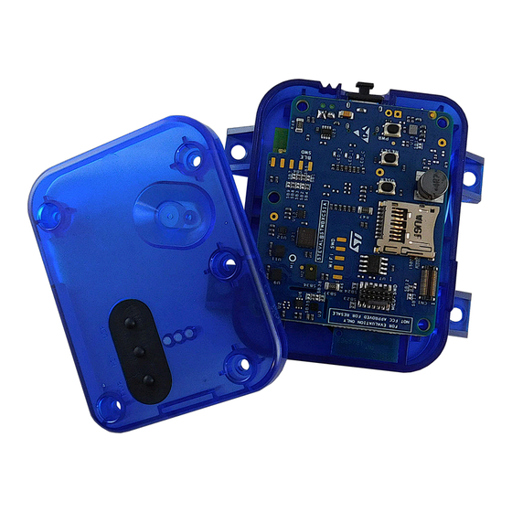
Figure 1.
STWIN.box mounted with the plastic case
UM2965
User manual
development kit
ST-LINK
debugger, a
www.st.com
Advertisement
Table of Contents

Related Manuals for ST STEVAL-STWINBX1


Summary of Contents for ST STEVAL-STWINBX1
-
Page 1: Figure 1. Stwin.box Mounted With The Plastic Case
Introduction The STWIN.box (STEVAL-STWINBX1) is a development kit and reference design that simplifies prototyping and testing of advanced industrial sensing applications in IoT contexts such as condition monitoring and predictive maintenance. It is an evolution of the original STWIN kit (STEVAL-STWINKT1B) and features a higher mechanical accuracy in the measurement of vibrations, an improved robustness, an updated BoM to reflect the latest and best-in-class MCU and industrial sensors, and an easy-to-use interface for external add-ons. -
Page 2: Getting Started
Industrial grade digital MEMS microphone (IMP34DT05) – Analog MEMS microphone with frequency response up to 80 kHz (IMP23ABSU) • Expandable via a 34-pin FPC connector Kit components STEVAL-STWINBX1 development kit includes: • the STWIN core system (main board); • a plastic case with M3 bolts;... -
Page 3: Layout Of The Core System Board (Steval-Stwinbx1) Components
UM2965 Layout of the core system board (STEVAL-STWINBX1) components Figure 2. STEVAL-STWINBX1 components Layout of the core system board (STEVAL-STWINBX1) components Figure 3. Layout of the core system board top components UM2965 - Rev 1 page 3/58... -
Page 4: Core System Board
UM2965 Core system board Figure 4. Layout of the core system board bottom components Core system board Figure 5. STEVAL-STWINBX1 block diagram UM2965 - Rev 1 page 4/58... -
Page 5: Functional Blocks
UM2965 Functional blocks Figure 6. STEVAL-STWINBX1 evaluation kit (top view) Figure 7. STEVAL-STWINBX1 evaluation kit (bottom view) Functional blocks 1.6.1 Sensing The core system board offers a comprehensive range of sensors specifically designed to support industrial applications and satisfy the demanding requirements of the Industry 4.0. -
Page 6: Figure 8. Steval-Stwinbx1 - Overview Of The Sensing Components
UM2965 Functional blocks Figure 8. STEVAL-STWINBX1 - overview of the sensing components The motion sensors communicate with the STM32U585AI microcontroller via SPI in order to accommodate the high data rates, whereas the magnetometer and environmental sensors communicate via I²C. The suitably filtered... -
Page 7: Table 1. Ilps22Qs I/O Configuration
UM2965 Functional blocks Figure 10. STEVAL-STWINBX1 - sensors on the bottom side • ILPS22QS MEMS pressure sensor • STTS22H digital temperature sensor • TSV912 wide-bandwidth (8 MHz) rail-to-rail I/O op-amp • ISM330DHCX iNEMO IMU, 3D accelerometer and 3D gyroscope with Machine Learning Core and Finite State Machine •... -
Page 8: Table 2. Stts22H I/O Configuration
UM2965 Functional blocks The sensor is housed in a small 2 x 2 x 0.50 mm 6-lead UDFN package with the exposed pad down for a better temperature match with the surrounding environment. STTS22H is factory-calibrated and requires no additional calibration. STTS22H units are 100% tested on a production setup that is NIST traceable and verified with equipment calibrated in accordance with the IATF 16949:2016 standard. -
Page 9: Table 4. Iis3Dwb I/O Configuration
The device integrates a 3 kB first-in, first-out (FIFO) buffer to avoid any data loss and to limit intervention of the host processor. The ST MEMS sensor module family leverages the robust and mature manufacturing processes already used for the production of micromachined accelerometers and gyroscopes to serve automotive, industrial, and consumer markets. -
Page 10: Table 6. Iis2Iclx I/O Configuration
UM2965 Functional blocks 1.6.1.7 IIS2ICLX IIS2ICLX is a high-accuracy (ultra-low noise, high stability, and repeatability) and low-power two-axis linear accelerometer with digital output. IIS2ICLX has a selectable full scale of ±0.5/±1/±2/±3 g. It can provide the measured accelerations to the application over an I²C or SPI digital interface. -
Page 11: Processing And Connectivity
UM2965 Functional blocks Table 8. IMP23ABSU I/O configuration Configuration ADC1_IN2 ADC1_IN1 (REF) 1.6.1.10 IMP34DT05 IMP34DT05 is an ultra-compact, low-power, omnidirectional, digital MEMS microphone with a capacitive sensing element and an IC interface. The sensing element, capable of detecting acoustic waves, is manufactured using a specialized silicon- micromachining process dedicated to producing audio sensors. -
Page 12: Figure 11. Main Connectivity Components And The Stm32U585Ai Processing Unit
UM2965 Functional blocks Figure 11. Main connectivity components and the STM32U585AI processing unit Each connectivity component is connected to an independent bus on the STM32U585AI MCU, so all of them can be individually configured. Figure 12. MCU and connectivity components (top view) UM2965 - Rev 1 page 12/58... -
Page 13: Figure 13. Mcu And Connectivity Components (Bottom View)
UM2965 Functional blocks Figure 13. MCU and connectivity components (bottom view) ® ® • U20: STM32U585AI ultra-low-power Arm Cortex -M33 with FPU and TrustZone at 160 MHz; ® • BlueNRG-M2SA Bluetooth low energy v5.2 wireless technology module; • STSAFE-A110 authentication and brand protection secure solution; •... -
Page 14: Table 10. Bluenrg2-M2 I/O Configuration
UM2965 Functional blocks The device offers one fast 14-bit ADC (2.5 Msps), one 12-bit ADC (2.5 Msps), two comparators, two operational amplifiers, two DAC channels, an internal voltage reference buffer, a low-power RTC, four 32-bit general-purpose timers, two 16-bit PWM timers dedicated to motor control, three 16-bit general-purpose timers, two 16-bit basic timers, and four 16-bit low-power timers. -
Page 15: Table 11. Mxchip Emw3080 I/O Configuration
UM2965 Functional blocks Figure 14. MXCHIP EMW3080 The main features of the MXCHIP EMW3080 module are: • IEEE 802.11n D7.0, OFDM-72.2 Mbps, single-stream width of 20 MHz, and short GI; • IEEE 802.11g, OFDM 54 Mbps; • IEEE 802.11b, DSSS 11 Mbps; •... -
Page 16: Table 12. Str485Lv I/O Configuration
UM2965 Functional blocks Table 12. STR485LV I/O configuration Configuration USART3_TX USART3_RX PD12 USART3_RTS 1.6.2.5 USB connector The on-board USB Type-C connector can be used for both power supply and data transfer (USB device only). You can find several examples of USB class implementation in the STM32 software packages. Table 13. -
Page 17: Power Management
UM2965 Functional blocks • X1, which is a 16 MHz high speed external (HSE) oscillator for the MCU; • X2, which is a 32.768 kHz low speed external (LSE) oscillator for the RTC embedded in the MCU. 1.6.3 Power management STWIN.box core system board includes a wide range of power management features that enable very low power consumption in final applications. - Page 18 UM2965 Functional blocks • U16, U19: ST1PS02CQ, 400 mA synchronous step-down converter • U15: STBC02AJR Li-Ion linear battery charger • U22: TCPP01-M12, USB Type-C™ port protection for Sink applications • U25: STEF05SGR, electronic fuse for 5 V line • Q1: STL6N3LLH6, N-channel 30 V, 6 A power MOSFET Protections and connectors •...
- Page 19 UM2965 Functional blocks Thanks to its ultra-low noise value and high PSRR, the LDLN025 provides a very clean output, suitable for ultra-sensitive loads. It is stable with ceramic capacitors. The enable logic control function makes the device enter shutdown mode, with a total current consumption lower than 1 μA.
-
Page 20: Table 16. Batt1 Connector Pins And Signals
UM2965 Functional blocks Figure 17. BATT1 connector Table 16. BATT1 connector pins and signals Signal BATT1 connector Pin 1 BAT_NC Pin 2 VBAT Pin 3 1.6.3.9 Power supply Different sources can supply the STWIN.box core system board: • V_USB: through USB-Type C connector (sink only, 5 V). •... -
Page 21: Figure 18. Stwin.box Core System Board - Power Supply Block Diagram
UM2965 Functional blocks Figure 18. STWIN.box core system board - power supply block diagram 1.6.3.10 Power on or off procedure If the STWIN.box core system board is not powered via a battery, the board turns on or off when you connect or disconnect an external supply, respectively. -
Page 22: Figure 19. Stwin.box Core System Resistors And Solder Bridges (Top View)
UM2965 Functional blocks Figure 19. STWIN.box core system resistors and solder bridges (top view) Figure 20. STWIN.box core system resistors and solder bridges (bottom view) UM2965 - Rev 1 page 22/58... -
Page 23: Table 17. Flexible Expansion Connector Pins
UM2965 Functional blocks 1.6.3.12 Buttons and LEDs STWIN.box core system board includes buttons and LEDs for user interaction: • buttons: – USR: generic user button; – PWR: connected to the STBC02 for integrated wake-up function and to the STM32 as a generic user button;... - Page 24 UM2965 Functional blocks Pin no. Description STM32 pin Signal USART_TX USART3_TX INT/I2Cz_SMB PG5/PG6/PD15 INT_EX USART_RX USART3_RX RESET GPIO1_EX USART_RTS PD13 USART3_RTS ADC_EX Not used TIM3_PWM GPIO3_EX PF10 GPIO3_EX GPIO2_EX GPIO2_EX SPIx_NSS PI0/PA15 SPI2_NSS/SPI3_NSS Not used SPIx_MOSIp PI3/PB5 SPI2_MOSI/SPI3_MOSI GPIO1/SAI1_SCK SAI1_SCK_A SPIx_MISOp PD3/PB4 SPI2_ MISO/SPI3_MISO...
-
Page 25: How To Assemble The Stwin.box
UM2965 How to assemble the STWIN.box How to assemble the STWIN.box The plastic case is designed to hold the STWIN.box core system board with the battery. The case consists of two parts, the bottom case and the cover. Through the cover you can access the three buttons: USR, RESET, and BOOT. -
Page 26: Figure 23. Stwin.box Core System Board Placed In The Bottom Case
UM2965 How to assemble the STWIN.box Step 3. Place the core system board inside the bottom case. Figure 23. STWIN.box core system board placed in the bottom case UM2965 - Rev 1 page 26/58... -
Page 27: Figure 24. Stwin.box Assembly
UM2965 How to assemble the STWIN.box Step 4. Close the plastic case with the cover and the five screws. Figure 24. STWIN.box assembly Figure 25. STWIN.box mounted with the plastic case UM2965 - Rev 1 page 27/58... -
Page 28: How To Program The Board
UM2965 How to program the board How to program the board How to program the STWIN.box in “USB mode” This is the easiest mode if you just want to download a binary into the board, without the need of any debugging capabilities. -
Page 29: Figure 26. Stm32Cubeprogrammer - Usb Mode Selection
UM2965 How to program the STWIN.box in “USB mode” Step 4. You can upgrade the firmware by following the steps below: Step 4a. Open STM32CubeProgrammer. Step 4b. Select [USB] on the top-right corner. Figure 26. STM32CubeProgrammer - USB mode selection Step 4c. -
Page 30: How To Program The Stwin.box With An External Debugger
UM2965 How to program the STWIN.box with an external debugger Step 4d. Go to the [Erasing & Programming] tab. Step 4e. Search for the new .bin or .hex binary file to be flashed into the board. Step 4f. Click on [Start Programming]. Figure 28. -
Page 31: Figure 30. Stwin.box, Adapter, And Stm32 Nucleo Development Board
UM2965 How to program the STWIN.box with an external debugger Alternatively, to offer more alternatives, an adapter to ST-LINK V2-1 (STM32 Nucleo development board) or a standard JTAG connector is included in the kit. When using an STM32 Nucleo development board as an external debugger, you need to disconnect the on-board STM32 by removing the two jumpers on CN2 (see the picture below). - Page 32 UM2965 How to program the STWIN.box with an external debugger • download one of the sample application binaries provided using STM32CubeProgrammer • recompile and flash memory one of the provided projects with your preferred IDE (STM32CubeIDE, ® EWARM, or, Keil UM2965 - Rev 1 page 32/58...
-
Page 33: Default Application
UM2965 Default application Default application STWIN.box core system is preprogrammed with a default application that is included in the FP-SNS-STBOX1 function pack. This function pack features: • Support for STBLESensor app (Android and iOS) ® • Bluetooth Low Energy pairing via NFC ®... -
Page 34: Figure 33. Firmware Upgrade Procedure
UM2965 Default application Figure 33. Firmware upgrade procedure UM2965 - Rev 1 page 34/58... -
Page 35: Schematic Diagrams
Schematic diagrams Figure 34. Core system board circuit schematic (1 of 8) Battery management 3.3V DC-DC ST1PS02CQTR 3V3_LDO DCDC_1 DCDC_1 PGOOD DCDC_1 3V3 400mA 3V3 150mA SB14 SB15 2.2uH 10uH VOUT C18 10uF C17 1uF 10uF 47uF 47uF VOUT2 C20 10uF LED_C1 CHRG SYS1... -
Page 36: Figure 35. Core System Board Circuit Schematic (2 Of 8)
Figure 35. Core system board circuit schematic (2 of 8) S YS 34 pin-Expansion J 13 12401598E4#2A Connector VBUS c VBUS c USB 3.0 Orientation: TX2+ TX1+ VEXT Odd pins should be on the side of the pcb TX2- TX1- VBUS VBUS CC2c... -
Page 37: Figure 36. Core System Board Circuit Schematic (3 Of 8)
Figure 36. Core system board circuit schematic (3 of 8) 3V3_S e ns ors 3V3_S e ns ors DCDC_1 3V3_S e ns ors PF12 CS _DWB Sensors current monitoring S P I2_CLK S P I2_MOS I 100nF 100nF 100nF 100nF TP 4 S P I2_CLK PH15... -
Page 38: Figure 37. Core System Board Circuit Schematic (4 Of 8)
Figure 37. Core system board circuit schematic (4 of 8) U20C S TM32U585AII3QU US ART2_TX_S TDC VDD_uC S B23 LED1 LED2 4 of 4 US ART2_TX VDD_uC US ART2_RX_S TDC S B24 US ART2_RX VS S S WDIO S B25 UART_TX_485 US ART2_TX VS S _1... -
Page 39: Figure 38. Core System Board Circuit Schematic (5 Of 8)
Figure 38. Core system board circuit schematic (5 of 8) 3V3_S e ns ors TP 12 IMP 34DT05TR PE10 ADF1_S DIO DOUT ADF1_CCK0 100nF HP Filter --> fc = 15.9 Hz MREF LP Filter --> fc = 99.4 KHz DAC for mic bias 2V75A IMP 23ABS UTR M1P _FILT... -
Page 40: Figure 39. Core System Board Circuit Schematic (6 Of 8)
Figure 39. Core system board circuit schematic (6 of 8) EMIF06-MS D02N16 3V3_S D_485 S D_DETECT WP /CD RDATA_VCC RDAT3_GND PC10 S DMMC_D2 DAT2_In DAT2_Ex PC11 S DMMC_D3 DAT3_In DAT3_Ex SD Card S DMMC_CMD CMD_In CMD_Ex PC12 S DMMC_CK CLK_In CLK_Ex S DMMC_D0 DAT0_In... -
Page 41: Figure 40. Core System Board Circuit Schematic (7 Of 8)
Figure 40. Core system board circuit schematic (7 of 8) VDD_BLE DCDC_1 VDD_BLE Default ON BLE_S WDCLK S B6 BLE_S P I_MOS I BLE_S WDIO S P I3_MOS I BLE_S P I_MIS O BLE current monitoring S B5 S P I3_MIS O BLE_RS T BLE_S P I_S CK S B4... -
Page 42: Figure 41. Core System Board Circuit Schematic (8 Of 8)
Figure 41. Core system board circuit schematic (8 of 8) DCDC_1 DCDC_1 10nF DCDC_1 DCDC_1 If closed, ST25DV is in Low Power Mode S T25DV64K-J FR6D3 VBat 4.7k S B45 LP D PB13 NFC_INT GP O V_EH I2C2_S DA S DA 100k I2C2_S CL S CL... -
Page 43: Figure 42. Adapter Board Circuit Schematic
Figure 42. Adapter board circuit schematic DIL24 Socket 34 pin-Expansion plug connector 2.2K (NC) 2.2K (NC) S B12 S P I_MIS O S B11 I2C_S DA S P I_MOS I S B10 S B17 I2C_S CL S B13 INT2 I2C_S CL S P I_CLK S B9 S P I_CLK... -
Page 44: Bill Of Materials
UM2965 Bill of materials Bill of materials Table 18. STEVAL-STWINBX1 bill of materials Item Q.ty Ref. Part/value Description Manufacturer Order code Table 19. STEVAL- Core system board ST Not available for separate sale STWBXCS1 Table 20. STEVAL-C34DIL24 Adapter board Not available for separate sale... - Page 45 UM2965 Bill of materials Item Q.ty Ref. Part/value Description Manufacturer Order code 0.22 µF, 16 V, Murata 0402 (1005 Ceramic Electronics GRM155R71C224KA12D metric), ±10%, capacitor North America 47 µF, 10 V, Murata C19, C55, C86, 0603 (1608 Ceramic Electronics ZRB18AR60J476ME01L metric), ±20%, capacitors North America...
- Page 46 UM2965 Bill of materials Item Q.ty Ref. Part/value Description Manufacturer Order code CON2, 2.54 mm PCB terminal Phoenix 1725656 pitch block Contact MicroSD - 502774-0891, MicroSD Molex 502774-0891 8p, SMT 12401598E4#2 USB 3.0 Amphenol ICC 12401598E4#2A Vishay Red, 0402 LED_C1 Red LED Semiconductor VLMS1500-GS08...
- Page 47 UM2965 Bill of materials Item Q.ty Ref. Part/value Description Manufacturer Order code TRANSISTOR MOSFET P DMP210DµFB4, DMP210DµFB4 Diodes DMP210DµFB4 1.05x0.65 mm µFDFN3 Incorporated DIODES INC 10 kohm, 0402 R1, R24, R30 (1005 metric), Resistors Yageo RC0402FR-0710KL ±1%, SMD 4.7 kohm, 0402 R2, R3, R6, (1005 metric), TE Connectivity...
- Page 48 UM2965 Bill of materials Item Q.ty Ref. Part/value Description Manufacturer Order code 160, 0402 (1005 TE Connectivity metric), 1/16 Resistor CRG0402F160R Passive Product W±1%, SMD 1k, 0402 (1005 metric), 1%, Resistor Yageo RC0402FR-071KL 560R, 0402 (1005 metric), Resistor Yageo RC0402FR-07560RL 1/16 W±1%, 2.7k, 0402 (1005 metric),...
- Page 49 UM2965 Bill of materials Item Q.ty Ref. Part/value Description Manufacturer Order code 6-line EMI filter and ESD EMIF06- protection for T- EMIF06-MSD02N16 MSD02N16 Flash and micro-SD card interfaces Dual full-scale, 1.26 bar and 4 ILPS22QSTR, bar, absolute HLGA 2X2X.8 digital output ILPS22QSTR 10L EXP.
- Page 50 UM2965 Bill of materials Item Q.ty Ref. Part/value Description Manufacturer Order code High accuracy, IIS2MDCTR, ultra-low-power, LGA2X2X0.7 12 3-axis digital IIS2MDCTR leads output magnetometer Li-ion linear STBC02AJR, battery charger chip scale with LDO, load STBC02AJR package 0.4 switches, and mm pitch reset generator 400 mA nano- quiescent...
-
Page 51: Table 20. Adapter Board Bill Of Materials
UM2965 Bill of materials Item Q.ty Ref. Part/value Description Manufacturer Order code NX2012SA 32.768KHz 32.7680 KHz, Crystal EXS00A-MU00527 Table 20. Adapter board bill of materials Item Q.ty Ref. Part/value Description Manufacturer Order code CON34-Plug, Connector Panasonic AXF6G3412A SMD, gold socket Electric Works SPC15503 DIL24 socket... -
Page 52: Kit Versions
STEVAL$STWINBX1A STEVAL$STWINBX1A schematic diagrams STEVAL$ISTWINBX1A bill of materials 1. This code identifies the STEVAL-STWINBX1 evaluation kit first version. The STEVAL-STWINBX1 kit contains the STEVAL$STWBXCS1A main board, the STEVAL$C34DIL24A expansion board, the STEVAL$FLTCB01A flexible cable, and the STEVAL$MKIGIBV4A adapter. UM2965 - Rev 1... -
Page 53: Regulatory Compliance Information
Directive 2015/863/EU (RoHS). Harmonized standards applied are listed in the EU Declaration of Conformity. Notice for Great Britain The kit STEVAL-STWINBX1 is in compliance with the UK Radio Equipment Regulations 2017. The full text of the UK declaration of conformity is available at the following internet address: www.st.com/en/evaluation-tools/ steval-stwinbx1.html... -
Page 54: Revision History
UM2965 Revision history Table 22. Document revision history Date Revision Changes 14-Dec-2022 Initial release. UM2965 - Rev 1 page 54/58... -
Page 55: Table Of Contents
Kit components ..............2 Layout of the core system board (STEVAL-STWINBX1) components ....3 Core system board . -
Page 56: List Of Tables
STEVAL-STWINBX1 bill of materials ........ -
Page 57: List Of Figures
STEVAL-STWINBX1 - overview of the sensing components ........ - Page 58 ST’s terms and conditions of sale in place at the time of order acknowledgment. Purchasers are solely responsible for the choice, selection, and use of ST products and ST assumes no liability for application assistance or the design of purchasers’...
Need help?
Do you have a question about the STEVAL-STWINBX1 and is the answer not in the manual?
Questions and answers