Table of Contents
Advertisement
Quick Links
Getting started with the STEVAL-2STPD01 USB Type-C™ Power Delivery dual
port adapter based on the STPD01 programmable buck converter
Introduction
The
STEVAL-2STPD01
is an evaluation kit composed of an expansion board containing two Type-C ports and integrating
two
STPD01PUR
programmable buck converters for USB Power Delivery, and the
development board.
The kit exploits the characteristics of the
UCPD peripheral embedded in the
USB Type-C and PD dual port source adapter with power sharing capability.
Once the input power rate is fixed, the kit is able to balance the power on the two ports, supporting the requests sent by the
USB PD devices connected to each port.
Taking advantage of
STPD01PUR
(60 W for each port) according to the DC input power.
The expansion board has been specifically developed to be stacked on the
capability of its microcontroller to manage two UCPD peripherals at the same time. It also embeds the
Type-C port protection for Source applications and the
To fully demonstrate the USB Type-C and Power Delivery functionalities of the solution, the
containing the demo application example, has been designed for the
The solution is compliant with USB Type-C 2.1 and PD 3.1 specifications.
UM2880 - Rev 1 - November 2021
For further information contact your local STMicroelectronics sales office.
STPD01PUR
programmable buck regulator controlled through I²C interface, and the
STM32G071RBT6
microcontroller supported by a dedicated firmware stack to implement a
characteristics to output several voltage levels, the solution is able to manage up to 120 W
L7983PU50R
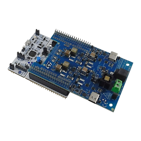
Figure 1.
STEVAL-2STPD01 evaluation kit
NUCLEO-G071RB
NUCLEO-G071RB
development board using the
synchronous step-down switching regulator.
STSW-2STP01
NUCLEO-G071RB
STM32 Nucleo development board.
UM2880
User manual
STM32 Nucleo-64
TCPP02-M18
USB
software package,
www.st.com
Advertisement
Table of Contents

Related Manuals for ST STEVAL-2STPD01


Summary of Contents for ST STEVAL-2STPD01
- Page 1 UM2880 User manual Getting started with the STEVAL-2STPD01 USB Type-C™ Power Delivery dual port adapter based on the STPD01 programmable buck converter Introduction STEVAL-2STPD01 is an evaluation kit composed of an expansion board containing two Type-C ports and integrating STPD01PUR...
-
Page 2: Getting Started
Figure 2. STEVAL-2STPD01 evaluation kit: NUCLEO-G071RB development board and expansion board UM2880 - Rev 1 page 2/41... -
Page 3: Nucleo-G071Rb Development Board
The STM32 Nucleo-64 boards do not require any separate probe as they integrate the ST-LINK/V2-1 debugger/ programmer. They embed comprehensive free STM32 software libraries and examples available with the STM32CubeG0 MCU package. -
Page 4: Expansion Board
UM2880 System architecture 1.2.2 Expansion board Figure 4. Expansion board schematic diagram main blocks 05 Protection + Type-C conn. CC1_Px D_VDD CC2_Px R800 EN_TCPP02_Px FLGn_TCPP02_Px ADDR_TCPP02_Px VBUSx_M R801 ISENSE_Px 0 N.M. VIN_24V VOUT BUSx EN_STPD01_Px D_VDD ALRT_STPD01_Px GND_Sign0 Pon_STPD01_Px R802 CSENS_STPD01_Px ADD_STPD01_Px GND_Sign0... -
Page 5: Figure 5. Expansion Board Main Functional Blocks (Top View)
UM2880 System architecture Figure 5. Expansion board main functional blocks (top view) ST morpho connectors (CN300, CN301) STPD01PUR programmable buck converter for USB Power Delivery (U400, U600) TSV991AILT rail-to-rail op-amp (U401, U501, U601, U701) TCPP02-M18 Type-C port protection for Source (U500, U700) -
Page 6: Figure 6. Input Power Connectors (J800 And J801)
GND_MAIN Note: STEVAL-2STPD01 has been designed to target 120 W output power when the input source is a DC power supply with 24 V and 6 A capability at least. This type of power supply has to be connected to J801 power connector. -
Page 7: Figure 8. L7983Pu50R Stage
UM2880 System architecture Figure 8. L7983PU50R stage 1^,3 L7983PU50R U200 VDD_5V VDD_5V L201 VOUT/FB VDD_5V C204 VBIAS 2.2uF 47uH 24V_Input C205 0.1uF R205 EN/UVLO C207 C206 0.47uF LNM/LCM R206 R207 R208 R209 0 N.M. 0 N.M. L7983PU50R can deliver up to 300 mA DC, with a wide input voltage range (from 3.5 V up to 48 V). The device features dynamic low consumption mode (LCM) to low noise mode (LNM) transitions. -
Page 8: Figure 10. Stpd01 Usbpd Programmable Buck Converter (U400, For Port P0)
UM2880 System architecture STPD01PUR programmable buck converters (U400 and U600) constitute the core of these blocks. These devices, controlled by the STM32G071RBT6 microcontroller through I C communication and GPIOs, set the correct level of voltage and current every time a new power negotiation is accomplished with a Sink platform connected to a port Type-C connector (P0 or P1). -
Page 9: Figure 12. D400 And D401 Indicator Leds (For Port P0)
UM2880 System architecture Figure 12. D400 and D401 indicator LEDs (for port P0) VCC_3.3V VCC_3.3V R409 R410 1.2k 3.3k LED GREEN LED BLUE D400 D401 Q400 Q401 2N7002E-T1-GE3 2N7002E-T1-GE3 Pon_STPD01_Px ENB_STPD01_Px 1.2.2.4 Protection and Type-C connector block The last section of the expansion board contains the TCPP02-M18 (U500 and U600) USB Type-C protections and the receptacles (CN500 and CN700) which gather the V... -
Page 10: Figure 14. Vbus Path Load Switch Based On Stl11N3H6 (Q500 And Q501) Driven By Tcpp02-M18
UM2880 System architecture Figure 14. path load switch based on STL11N3H6 (Q500 and Q501) driven by TCPP02-M18 TP500 5001 Q500 Q501 STL11N3LLH6 STL11N3LLH6 BUSx R500 VBUSx VBUSx BUSx 1^,4 10mOhms C500 D500 4.7uF ESDA25P35-1U1M Moreover, the device measures the current on the V through an external resistor (R500 or R600) and on the path through two pins (I and V... -
Page 11: Application Example Setup
D+_Px N.M. Application example setup STSW-2STPD01 software package for the STEVAL-2STPD01 evaluation kit contains an application example specific for the STM32G071RBT6 microcontroller embedding the USB Type-C and Power Delivery management with the two ports and a module featuring the power sharing on these two stages. -
Page 12: How To Run The Application With The Maximum Power Rate Input
How to run the application with the maximum power rate input Step 1. Verify that a jumper closes the expansion board J200 header, as highlighted in pink in the figure below. Figure 17. STEVAL-2STPD01 evaluation kit - J200 closed by a jumper UM2880 - Rev 1 page 12/41... -
Page 13: Figure 18. 24 V, 6 A Dc Power Supply Connected To J801 Connector
Connect a Sink to one port through a Type-C cable. After connecting the 24 V, 6 A DC power supply, the STEVAL-2STPD01 transmits the list of the available PDOs (5 V, 9 V, 15 V and 20 V, up to 3 A) to the attached Sink which requests the suitable one. -
Page 14: How To Set Up The Steval-2Stpd01 Power Input
Repeat step 3 for the other port with the other Sink. Figure 19. STEVAL-2STPD01 evaluation kit connection example - charging two mobile phones Note: Using a 24 V, 6 A power supply, each port of the kit can provide the maximum power of 60 W and four PDOs: 5 V, 9 V, 15 V and 20 V, up to 3 A. -
Page 15: Figure 20. Connections For Input Power Setup
UM2880 Application example setup Step 1. Download and install the STM32CubeMonUCPD, connect your power supply to one of the STEVAL-2STPD01 power connectors (J800 or J801) and connect the NUCLEO-G071RB USB_STLINK CN2 connector to the PC through a micro-B USB cable. -
Page 16: Figure 21. Stm32Cubemonucpd (1 Of 2)
UM2880 Application example setup Step 2. Run STM32CubeMonUCPD. Step 2a. In the first window, double-click the name of board to select it. Figure 21. STM32CubeMonUCPD (1 of 2) Step 2b. In the next window, double-click on the port number (1 or 2) to select it. Figure 22. -
Page 17: Table 1. Syntax To Insert New Input Power Values
UM2880 Application example setup Step 3. In the [Message Selector] tab, select [Send free text] by scrolling the right side bar or typing "free" in the [Filtering messages] text box. In the Free text box, you can insert the values of the used power supply for nominal voltage, current and power, on the basis of the syntax described in Table Figure 23. -
Page 18: How To Reprogram The Nucleo-G071Rb
The following procedure describes how to restore the initial application example (contained in the STSW-2STPD01 software package) in the STM32G071RBT6 microcontroller. To reprogram the NUCLEO-G071RB you need: • STEVAL-2STPD01 evaluation kit • STSW-2STPD01 software package • a PC/laptop with at least a type-A port UM2880 - Rev 1 page 18/41... -
Page 19: Figure 26. Nucleo-G071Rb Jp2 Set On 1-2 Before Programming
Download, unzip and save STSW-2STPD01 software package. Step 2. Open the firmware\project\STEVAL-2STPD01\bin folder and target the bin file. You can also open the source code project with your favourite IDE and generate a new binary file or start a debug session. Step 3. -
Page 20: Figure 27. Nucleo-G071Rb Connected To The Laptop To Program The Testing Firmware
UM2880 Application example setup Step 4. Connect the USB Micro-B cable to the NUCLEO-G071RB USB micro-B USB_STLINK connector CN2, and then connect the type-A side to the laptop type-A port as shown below. Figure 27. NUCLEO-G071RB connected to the laptop to program the testing firmware Step 5. -
Page 21: Figure 28. Drag And Drop The Testing Firmware To The New Mapped Device
Step 7. Disconnect the USB cable from the NUCLEO-G071RB board, move the jumper on JP2 connector from position 1-2 (ST-LINK) to position 5-6 (E5V), as shown below. Figure 29. Programmed NUCLEO-G071RB with JP2 set, before being stacked under the expansion board... - Page 22 UM2880 Application example setup Step 8. Stack the expansion board on the NUCLEO-G071RB board, ensuring that the expansion board morpho connectors (CN300 and CN301) perfectly fit into the NUCLEO-G071RB connectors. Note: The same procedure can be also followed to program the board with a new application example to test specific characteristics of your own application, adding or removing some software feature.
-
Page 23: Schematic Diagrams
The schematic diagrams below refer to the expansion board included in the STEVAL-2STPD01 evaluation kit. For the schematic diagrams of the NUCLEO-G071RB development board, see the related page. Figure 30. STEVAL-2STPD01 circuit schematic (1 of 7) 05 Protection + Type-C conn. CC1_Px D_VDD CC2_Px R800 EN_TCPP02_Px... -
Page 24: Figure 31. Steval-2Stpd01 Circuit Schematic (2 Of 7)
Figure 31. STEVAL-2STPD01 circuit schematic (2 of 7) TP200 TP201 5001 5001 L200 Q200 24V_Input V_PLUG 1^,4,5 STL9P3LLH6 D200 C200 C201 C202 SMM4F28A TP202 10uF BNX002-11 22uF 220uF R200 5001 N.M. 100k R201 R202 210k R203 24V_Sense 1^,3 R204 C203 0.22uF... -
Page 25: Figure 32. Steval-2Stpd01 Circuit Schematic (3 Of 7)
Figure 32. STEVAL-2STPD01 circuit schematic (3 of 7) NUCLEO-G071RB MORPHO CONNECTORS CN302 CN303 IOREF RESET AVDD CN300 +3V3 CN301 PC10 PC11 PC12 CC2_P1 FLGn_TCPP02_P1 1^,2 VSYS EN_TCPP02_P1 PA14 AVDD CC1_P1 1^,4,5,6,7 IOREF 61300811821 N.M. A_VDD PA13 RESET 61301011821 N.M. PA12... -
Page 26: Figure 34. Steval-2Stpd01 Circuit Schematic (5 Of 7)
Figure 34. STEVAL-2STPD01 circuit schematic (5 of 7) TP600 TP601 5001 5001 TP602 C600 5001 U600 C601 0.1uF L600 R600 VOUT PVIN8 LX15 24V_Input PHASE_x VA_x VBUS_Px VIN_24V 1^,2 1^,7 PVIN9 LX14 LX13 10uH TP604 25mOhms R601 Pon_STPD01_Px 5001 ENB_STPD01_Px... -
Page 27: Figure 35. Steval-2Stpd01 Circuit Schematic (6 Of 7)
Figure 35. STEVAL-2STPD01 circuit schematic (6 of 7) Port Protection & BUS Control TP500 DVDD 5001 D_VDD 1^,4,5 Q500 Q501 STL11N3LLH6 STL11N3LLH6 BUSx R500 VBUSx VBUSx BUSx 1^,4 U500 10mOhms TCPP02-M18 Px_Iana C500 D500 GND1 IANA 4.7uF ESDA25P35-1U1M CC2c_Px CC2_Px... -
Page 28: Figure 36. Steval-2Stpd01 Circuit Schematic (7 Of 7)
Figure 36. STEVAL-2STPD01 circuit schematic (7 of 7) Port Protection & BUS Control TP700 DVDD 5001 D_VDD 1^,4,5 Q700 Q701 STL11N3LLH6 STL11N3LLH6 BUSx R700 VBUSx VBUSx BUSx 1^,5 U700 10mOhms TCPP02-M18 Px_Iana C700 D700 GND1 IANA 4.7uF ESDA25P35-1U1M CC2c_Px CC2_Px... -
Page 29: Bill Of Materials
UM2880 Bill of materials Bill of materials Table 2. STEVAL-2STPD01 bill of materials Item Q.ty Ref. Part/value Description Manufacturer Order code Table 3. Expansion Expansion board bill of materials board NUCLEO-G071RB (for the related BOM, Development NUCLEO- see the relevant... - Page 30 UM2880 Bill of materials Item Q.ty Ref. Part/value Description Manufacturer Order code 47 µF, Stacked CAP CER Murata C407 C607 SMD, 2 J-Lead, 47UF 35V KRM55WR7YA476MH01K Electronics 35 V, ±10 % X7R SMD CAP CER 10000 pF, 0603 10000PF Würth C411 C611 (1608 Metric), 25 885012206065...
- Page 31 UM2880 Bill of materials Item Q.ty Ref. Part/value Description Manufacturer Order code LED BLUE, 0805 LED BLUE Würth D401 D601 (2012 Metric), 20 CLEAR 0805 150080BS75000 Elektronik High-power ESDA25P35-1U1 transient D500 D700 M, QFN-2L, 1400 ESDA25P35-1U1M voltage W (1.4 kW) W suppressor FERRITE Ohm@100MHz,...
- Page 32 UM2880 Bill of materials Item Q.ty Ref. Part/value Description Manufacturer Order code N-channel 30 V, 6 STL11N3LLH6, mOhm typ., Q500 Q501 PowerFLAT, 3.3 x 11 A STL11N3LLH6 Q700 Q701 STripFET H6 power MOSFET CHIP 100k, 0402 (1005 RESISTOR R200 Metric), 0.063W, Yageo RC0402FR-07100KL SMD 1%...
- Page 33 UM2880 Bill of materials Item Q.ty Ref. Part/value Description Manufacturer Order code CHIP 10 k, 0402 (1005 R405 R605 RESISTOR Metric), 0.063 W, N.M. SMD 1% 1/16 W, ±1 % 1/16W 0402 CHIP 0, 0402 (1005 RESISTOR R406 R606 Metric), 0.063 W, Yageo RC0402FR-070RL SMD 1%...
- Page 34 UM2880 Bill of materials Item Q.ty Ref. Part/value Description Manufacturer Order code TP606 TP607 TP700 60 V 300 mA synchronous step-down L7983PU50R, switching U200 DFN 3X3X0.8 L7983PU50R regulator 10L pitch 0.5 with 10 µA quiescent current Programmab STPD01PUR, le buck U400 U600 QFN-24L, 3X4 converter for...
-
Page 35: Kit Versions
UM2880 Kit versions Kit versions Table 4. STEVAL-2STPD01 versions Finished good Schematic diagrams Bill of materials STEVAL$2STPD01XA STEVAL$2STPD01XA schematic diagrams STEVAL$2STPD01XA bill of materials NUG071RB$AU2 schematic diagrams NUG071RB$AU2 bill of materials NUG071RB$AU2 1. This code identifies the expansion board version. -
Page 36: Regulatory Compliance Information
UM2880 Regulatory compliance information Regulatory compliance information Formal Notice Required by the U.S. Federal Communications Commission FCC NOTICE: This kit is designed to allow: (1) Product developers to evaluate electronic components, circuitry, or software associated with the kit to determine whether to incorporate such items in a finished product and (2) Software developers to write software applications for use with the end product. -
Page 37: Revision History
UM2880 Revision history Table 5. Document revision history Date Revision Changes 22-Nov-2021 Initial release. UM2880 - Rev 1 page 37/41... -
Page 38: Table Of Contents
1.3.2 How to set up the STEVAL-2STPD01 power input ......14 1.3.3... -
Page 39: List Of Tables
STEVAL-2STPD01 bill of materials........ -
Page 40: List Of Figures
STEVAL-2STPD01 evaluation kit - J200 closed by a jumper ....... . - Page 41 ST’s terms and conditions of sale in place at the time of order acknowledgement. Purchasers are solely responsible for the choice, selection, and use of ST products and ST assumes no liability for application assistance or the design of Purchasers’...
Need help?
Do you have a question about the STEVAL-2STPD01 and is the answer not in the manual?
Questions and answers