Table of Contents
Advertisement
Quick Links
Introduction
This document describes the development kits for the S2-LP device and related hardware and software
components.
The S2-LP is an ultra low-power, low data rate, sub-1 GHz transceiver.
The following S2-LP kits are available:
1.
S2-LP development platform for 430-470 MHz (order code: STEVAL-FKI433V1)
2.
S2-LP development platform for 860-940 MHz (order code: STEVAL-FKI868V1)
3.
S2-LP development platform for 860-940 MHz with external FEM (order code: STEVAL-FKI915V1)
December 2016
Getting started with the S2-LP development kits
DocID030087 Rev 1
UM2149
User manual
www.st.com
1/35
Advertisement
Table of Contents

Related Manuals for ST STEVAL-FKI433V1


Summary of Contents for ST STEVAL-FKI433V1
- Page 1 The S2-LP is an ultra low-power, low data rate, sub-1 GHz transceiver. The following S2-LP kits are available: S2-LP development platform for 430-470 MHz (order code: STEVAL-FKI433V1) S2-LP development platform for 860-940 MHz (order code: STEVAL-FKI868V1) S2-LP development platform for 860-940 MHz with external FEM (order code: STEVAL-FKI915V1)
-
Page 2: Table Of Contents
Contents Overview ..................6 System requirements ................ 6 STSW-S2LP-DK development kit setup ..........6 Hardware description ..............7 STEVAL-FKI868V1 and STEVAL-FKI433V1 evaluation boards ..7 2.1.1 S2-LP connections ................8 2.1.2 STEVAL-FKI868V1 and STEVAL-FKI433V1 power ......9 STEVAL-FKI915V1 evaluation board ..........9 2.2.1... - Page 3 UM2149 Contents 3.9.4 Device emulator ................30 Firmware examples ............... 31 Release notes ................32 License ................... 33 Revision history ................34 DocID030087 Rev 1 3/35...
- Page 4 List of tables UM2149 List of tables Table 1: S2-LP: FKI868V1 and FKI433V1 evaluation board pin description ..........8 Table 2: S2-LP: FKI915V1 evaluation board pin description ..............10 Table 3: STEVAL-FKI915V1 expansion board jumper description ............11 Table 4: Document revision history ......................34 4/35 DocID030087 Rev 1...
- Page 5 UM2149 List of figures List of figures Figure 1: STEVAL-FKI868V1 evaluation board features ................7 Figure 2: STEVAL-FKI915V1 evaluation board features ................9 Figure 3: NODE_L152RE disk drive ......................13 Figure 4: Connection setup 1: 1 PC with S2-LP-DK GUI ................. 13 Figure 5: Connection setup 2: 2 PCs with S2-LP-DK GUI ................
-
Page 6: Overview
Overview UM2149 Overview This section describes all the software and hardware components of the S2-LP kits. System requirements The STSW-S2LP-DK application GUI has the following minimum requirements: • PC with Intel® or AMD® processor running Windows (XP SP3, Vista, 7 or 10) •... -
Page 7: Hardware Description
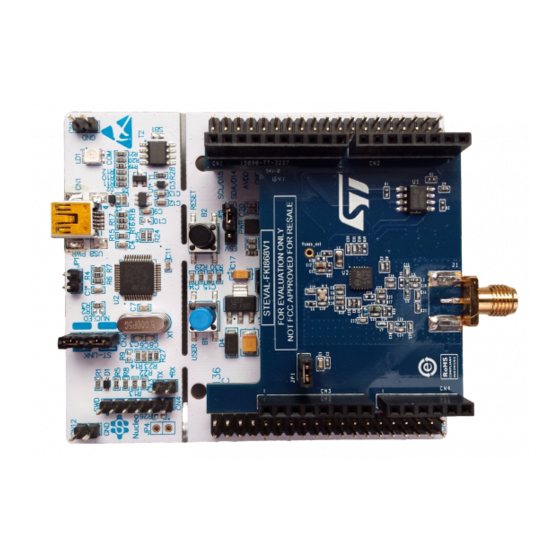
Hardware description Hardware description STEVAL-FKI868V1 and STEVAL-FKI433V1 evaluation boards The STEVAL-FKI868V1 and the STEVAL-FKI433V1 evaluation boards are designed to work in the 860-940 MHz and in the 430-470 MHz band, respectively. Some features on the boards are (see Figure 1: "STEVAL-FKI868V1 evaluation board features"):... -
Page 8: S2-Lp Connections
Hardware description UM2149 2.1.1 S2-LP connections S2-LP signal test points are split across two rows which are Arduino compliant connectors: CN1, CN3 and CN2, CN4. The S2-LP shield is connected to the Nucleo motherboard via the Arduino compliant connectors. The connectors and pin names below are used in the STEVAL-FKIxxxV1 schematic diagram. -
Page 9: Steval-Fki868V1 And Steval-Fki433V1 Power
UM2149 Hardware description 2.1.2 STEVAL-FKI868V1 and STEVAL-FKI433V1 power The board can be powered by the Nucleo evaluation board mini USB connector. When the JP1 jumper is fitted (H in Figure 1: "STEVAL-FKI868V1 evaluation board features"), the radio section is supplied. -
Page 10: S2-Lp Connections
Hardware description UM2149 2.2.1 S2-LP connections S2-LP signal test points are split across two rows which are Arduino compliant connectors: CN1, CN3 and CN2, CN4. The S2-LP shield is connected to the NUCLEO motherboard using the Arduino compliant connectors. The connectors and pin names below are used in the STEVAL-FKI915V1 schematic diagram. -
Page 11: Steval-Fki915V1 Power
LD2: green (user LED) • LD3: red (microcontroller power) 2.3.3 Embedded ST-LINK The ST-LINK/V2-1 programming and debugging tool is integrated in the STM32 Nucleo boards. The ST-LINK/V2-1 makes the STM32 Nucleo boards "mbed" enabled. 2.3.4 STM32L152RE microcontroller The STM32L152RE 64-pin microcontroller on the NUCLEO-L152RE development board is programmed by the S2-LPS2-LP DK firmware and is used to drive the device through the GUI or through the library examples. -
Page 12: Hardware Setup
Connect an antenna to the SMA connector Ensure the jumper configuration on the board is correct (see Section 2.1.2: "STEVAL- FKI868V1 and STEVAL-FKI433V1 power" Section 2.2.2: "STEVAL-FKI915V1 power" Connect the STM32 Nucleo board to the PC through a USB cable (via CN5 connector) Check the power LED DL4 light is on. -
Page 13: Gui Software Description
UM2149 GUI software description GUI software description The S2-LP DK GUI included in the software package is a graphical user interface that can be used to interact with and evaluate the capabilities of the S2-LP device. You can run this utility by clicking on the S2-LP GUI icon on the desktop or under: Start →STMicroelectronics →S2-LP DK X.X.X →S2-LP DK This version of the GUI for S2-LP exclusively targets RF evaluation performance and only provides the RF test window and the manipulation of the device configuration parameters. -
Page 14: Figure 6: S2-Lp Gui Main Window
GUI software description UM2149 Figure 5: Connection setup 2: 2 PCs with S2-LP-DK GUI During the tests, each S2-LP DK - DB can work as a transmitter (TX) or a receiver (RX). The TX device is used as a transmitter during the communication tests; the RX device is used as a receiver during the communication tests. -
Page 15: Connection Panel
[1.1 – 769.3] kHz. • output power interval: [-30.0 14.0] dBm if the Normal (without external PA) configuration is selected (as for the STEVAL-FKI433V1 or STEVAL-FKI868V1). • output power interval: [-8.0 27.0] dBm if the PA configuration is selected (as for the STEVAL-FKI915V1). -
Page 16: Rf Test Mode
GUI software description UM2149 Figure 8: S2-LP radio setting 3.2.3 RF test mode TX CW and TX PN9 commands put the S2-LP in test mode. Figure 9: RF test mode buttons Both tests require only one device connected to PC. 3.2.3.1 TX CW test To start this test mode:... -
Page 17: Packet Setting
UM2149 GUI software description The S2-LP stays in TX state until the "TX PN9 STOP" button is clicked. To change frequency, output power or modulation scheme, stop the running test first and then repeat steps 1 and 2 selecting the desired frequency, output power or modulation scheme during step 1. -
Page 18: Packet Setting: Wmbus
GUI software description UM2149 • Preamble length interval: [1 - 32] bytes. • Sync length interval: [1 - 4] bytes. • CRC: NO CRC. Poly 0x07 (1 byte). Poly 0x8005 (2 bytes). Poly 0x1021 (2 bytes). Poly 0x864CFB (3 bytes). Poly 0x04C011BB7 (4 bytes). -
Page 19: Transmission Test
UM2149 GUI software description Transmission test Selecting the "Transmission test" view, the user can access all the available packet tests to run the transmission. Figure 12: Transmission test panel Device role panel in the "Device role" panel in the left corner, you can set the main role of the device during transmission (RX and TX). - Page 20 GUI software description UM2149 lengths. If the value is 0, the RX timeout is infinite and the S2-LP remains in the RX state until it finds a correct SYNC word. HEX or ASCII radio buttons The data received can be displayed in HEX or ASCII format. If ASCII is set and a non- ASCII character is received, the representation automatically switches to HEX format.
- Page 21 UM2149 GUI software description Packet rate It is crucial to set the packet rate value greater than the packet duration. Otherwise, the received packet can be truncated or not received at all. Furthermore, the packet rate must be the same for both devices. Start/stop button The Start button runs the test and turns into a Stop button while the test is stopped.
-
Page 22: Low Level Commands
GUI software description UM2149 Low level commands Selecting the "Low level commands", you can access the S2-LP test modes, read the status and set the SMPS output voltage. Figure 13: Low level command panel The S2-LP status can be read by clicking the S2-LP state read button. The chip version is also shown. -
Page 23: Figure 14: Read/Write Register Window
UM2149 GUI software description Figure 14: Read/write register window • Through the "Read registers" box, you can specify the starting address and the number of registers to be read from there on. • Through the "Write registers" box, it is possible to specify the address and the value of a single register. -
Page 24: Running Rssi
GUI software description UM2149 Running RSSI The running RSSI tab allows the user to measure the power on the channel using the S2- LP running RSSI feature. The RSSI values are sampled and plotted in a graph (RSSI (dBm) vs time(s)). The polling interval is settable by the update timer spin-box. -
Page 25: How To Run A Ber Test Using A Signal Generator
UM2149 GUI software description How to run a BER test using a signal generator Through the low level command tab, you can put the S2-LP directly in RX mode through GPIOs; the packet handler is therefore totally bypassed and the demodulated data plus associated clock signal is available on two GPIOs. -
Page 26: Register Table
GUI software description UM2149 Register table On the right side of the GUI, a register table is shown by default (it can be hidden/shown using the “<<” button). The register table provides a quick and user-friendly way to modify the device registers and bit-fields. -
Page 27: Menu Bar
UM2149 GUI software description The single register can be expanded or compressed to show its logical fields by clicking on the white arrow to the left of each entry. When a field is modified, the corresponding register is automatically written in S2-LP. Moreover, if the register modifies a parameter of the radio part or packet, the corresponding tab is updated with the new field value. -
Page 28: Tools
GUI software description UM2149 3.9.2 Tools The Tools menu provides the following list: Figure 19: Tool list 3.9.2.1 Firmware upgrade The S2-LP firmware allows performing automatic firmware upgrade via the USB port. To upgrade the firmware: Launch the S2-LP DK GUI. Select the COM port of the NUCLEO board to upgrade. - Page 29 UM2149 GUI software description 3.9.2.3 Export code configuration This option generates a C-language list of instructions to write new values into the S2-LP registers. For example, the user can quickly find the device desired configuration using the GUI and then use this tool to obtain a C snippet that can be easily included in the program running on the microcontroller.
-
Page 30: Help
GUI software description UM2149 S2LPSpiWriteRegisters(0x2C, 1, tmp); tmp[0]= 0x00; /* reg. PCKTCTRL3 (0x2E) */ tmp[1]= 0x01; /* reg. PCKTCTRL2 (0x2F) */ tmp[2]= 0x30; /* reg. PCKTCTRL1 (0x30) */ S2LPSpiWriteRegisters(0x2E, 3, tmp); tmp[0]= 0x01; /* reg. PROTOCOL1 (0x3A) */ S2LPSpiWriteRegisters(0x3A, 1, tmp); tmp[0]= 0x41;... -
Page 31: Firmware Examples
Projects/Projects_Cube/S2LPLibrary_Examples/EWARM. Each program is an IAR configuration and can be compiled and flashed on the STM32 Nucleo board using the embedded ST-LINK. To use the project with IAR Embedded Workbench for ARM: open the Embedded Workbench for ARM and select File→Open→Workspace menu. -
Page 32: Release Notes
Release notes UM2149 Release notes The S2-LP DK SW package release notes are contained in Documents/S2LP_DK_release_notes/Release_Notes.html (html format). Open the file Documents/index.html for a global documentation index. 32/35 DocID030087 Rev 1... -
Page 33: License
UM2149 License License The S2-LP DK software package license file is accessible through the Documents/index.html file. DocID030087 Rev 1 33/35... -
Page 34: Revision History
Revision history UM2149 Revision history Table 4: Document revision history Date Version Changes 19-Dec-2016 Initial release. 34/35 DocID030087 Rev 1... - Page 35 ST products and/or to this document at any time without notice. Purchasers should obtain the latest relevant information on ST products before placing orders. ST products are sold pursuant to ST’s terms and conditions of sale in place at the time of order acknowledgement.
Need help?
Do you have a question about the STEVAL-FKI433V1 and is the answer not in the manual?
Questions and answers