
Related Manuals for SeaLevel Route 56


Summary of Contents for SeaLevel Route 56
- Page 1 Route 56. PCI USER MANUAL Part # 5101 Sealevel Systems, Inc Phone: (864) 843-4343 P.O. Box 830 FAX: (864) 843-3067 Liberty, SC 29657 USA www.sealevel.com...
-
Page 2: Table Of Contents
V.35..............................14 D - S ....................15 PPENDIX CREEN E - C .................. 16 PPENDIX OMPLIANCE OTICES ............... 16 EDERAL OMMUNICATIONS OMMISSION TATEMENT EMC D ....................... 16 IRECTIVE TATEMENT ..........................17 ARRANTY Trademarks ............................17 ©Sealevel Systems, Inc. SL9162 Revision 7/2006... -
Page 3: Introduction
10M bps in burst mode. By utilizing the Z16C32's 32 byte FIFO buffer coupled with 256K of on board memory, higher data rates are achieved. What’s Included The ROUTE 56.PCI is shipped with the following items. If any of these items are missing or damaged, contact the supplier. •... -
Page 4: Installation
HDLC/SDLC driver. The SeaMAC Configuration utility that configures the driver will inform you that you must add a driver before proceeding. For the ROUTE 56.PCI this feature is not to be used. After installing the software in Windows NT/2000 power down the computer and install the card. Power the system back up and the driver will automatically be loaded. -
Page 5: Technical Description
The Sealevel Systems’ ROUTE 56.PCI adapter was designed for seamless integration into any PCI based system. The ROUTE 56.PCI adapter requires a PCI slot, one IRQ, an 8 byte block of I/O address and a 16K block or 256K block of memory address. The memory range of this adapter can be configured to reside in the lower 1 Megabyte memory only or anywhere in upper memory. -
Page 6: Control And Status Registers Defined
See Interface Selection table for valid interface options SD0-SD15 Optional security feature. Unique value per customer or application. ( default value = FFFF) LIN/PAGE 1=256K linear block in high memory only, 0=16X16K pages in low or high memory, (0 on power-up) Sealevel Systems ROUTE 56.PCI Page 4... -
Page 7: Description
Technical Description Interface Selection The ROUTE 56.PCI supports a variety of electrical interfaces. Reference the Control and Status Register Definitions, found in the Technical Description section of this manual for this bit description. There is line termination on RXD, RXC, and TXC in the following modes: RS-530, RS-530A, RS-485T, and V.35. -
Page 8: I/O Signal Derivation
Technical Description I/O Signal Derivation The ROUTE 56.PCI input/output signals are directly generated via the Zilog 16C32 IUSC. The following table defines these signals, their origin pin and signal name following the conventions set by the 16C32 user’s manual. If using a Sealevel Systems, Inc. -
Page 9: Pin Connector Signal Layouts (Db-25 Male)
Technical Note: Please terminate any control signals that are not going to be used. The most common way to do this is connect RTS to CTS and RI. Also, connect DCD to DTR and DSR. Terminating these pins, if not used, will help insure you get the best performance from your adapter. Sealevel Systems ROUTE 56.PCI Page 7... -
Page 10: Rs-530 (Rs-422)
DSR+ is available by placing a jumper over E1. This will disable the use of Ring Indicator on RS-232, V.35, and RS-530A. In this mode the following signals will be available: DSRB DSR+ Data Set Ready Positive Input DSRA DSR- Data Set Ready Negative Input Sealevel Systems ROUTE 56.PCI Page 8... -
Page 11: Rs-485 Or Rs-485T
Receive Clock Negative Input TDB TX+ Transmit Positive Output TDA TX- Transmit Negative Output TSETB TSET+ Transmit Signal Element Timing Positive Output TSETA TSET- Transmit Signal Element Timing Negative Output Local Loop-back Output Remote Loop-back Output Sealevel Systems ROUTE 56.PCI Page 9... -
Page 12: Specifications
Mean Time Between Failures (MTBF) Greater than 150,000 hours. (Calculated) Physical Dimensions Board length 4.90 inches (12.446 cm.) Board Height including Goldfingers 4.00 inches (10.160 cm.) Board Height excluding Goldfingers 3.675 inches (9.335 cm.) Sealevel Systems ROUTE 56.PCI Page 10... -
Page 13: Appendixa - Troubleshooting
I/O address. 3. Make sure the Sealevel Systems adapter is using a unique IRQ. While the Sealevel Systems adapter does allow the sharing of IRQs, many other adapters (i.e. SCSI adapters and on-board serial ports) do not. The IRQ is typically selected via an on-board header block. -
Page 14: Appendixb - How T O Get Assistance
When calling for technical assistance, please have your user manual and current adapter settings. If possible, please have the adapter installed in a computer ready to run diagnostics. 3. Sealevel Systems provides an FAQ section on its web site. Please refer to this to answer many common questions. This section can be found at http://www.sealevel.com/faq.htm... -
Page 15: Appendixc - Electrical Interface
(usually +3 to +10 volts) represents a binary 0 (space) and -12 volts (-3 to -10 volts) denotes a binary 1 (mark). The RS-232 and the EIA/TIA-574 specification defines two type of interface circuits, Data Terminal Equipment (DTE) and Data Circuit-Terminating Equipment (DCE). The Sealevel Systems adapter is a DTE interface. RS-422 The RS-422 specification defines the electrical characteristics of balanced voltage digital interface circuits. -
Page 16: V.35
RS-232. The physical connector is a 34 pin connector that supports 24 data, clock and control signals. The physical connector is defined in the ISO-2593 standard. ITU V.35 specification defines two type of interface circuits, Data Terminal Equipment (DTE) and Data Circuit-Terminating Equipment (DCE). The Sealevel Systems adapter is a DTE interface. -
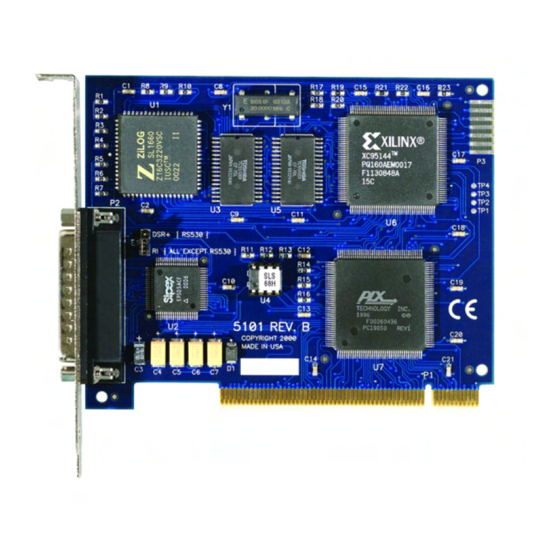
Page 17: Appendixd - Silk -Screen
Appendix D - Silk-Screen Appendix D - Silk-Screen 4.00" 4.90" 3.675" Sealevel Systems ROUTE 56.PCI Page 15... -
Page 18: Appendixe - Compliance Notices
Always use cabling provided with this product if possible. If no cable is provided or if an alternate cable is required, use high quality shielded cabling to maintain compliance with FCC/EMC directives. Sealevel Systems ROUTE 56.PCI Page 16... -
Page 19: Warranty
Sealevel Systems assumes no liability for any damages, lost profits, lost savings or any other incidental or consequential damage resulting from the use, misuse of, or inability to use this product. Sealevel Systems will not be liable for any claim made by any other related party.
Need help?
Do you have a question about the Route 56 and is the answer not in the manual?
Questions and answers