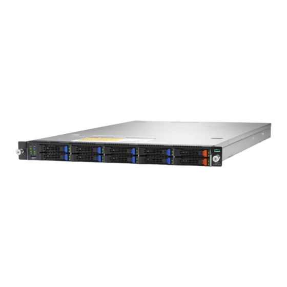
HPE Cloudline CL2100 / CL2200 Gen10 Server Troubleshooting Guide Abstract This document is for the person who installs, administers, services, and troubleshoots servers. This guide describes identification and maintenance procedures, and specifications and requirements for hardware components and software. Hewlett Packard Enterprise assumes you are qualified in the servicing of computer equipment, trained in recognizing hazards in pr oducts, and are familiar with weight and stability precautions.
BIOS POST Beep Code 1-2-1 PEI Beep Codes # of Beeps Description Memory not Installed. Memory was installed twice (InstallPeiMemory routine in PEI Core called twice) Recovery started DXEIPL was not found DXE Core Firmware Volume was not found Recovery failed S3 Resume failed Reset PPI is not available 1-2-2 DEX Beep Codes...
Chapter 2 Remote Troubleshooting 2-1 WebUI 2-1-1 To remote manage the server, login into BMC web UI. For first time use, enter the default user name and password. This can be found on label on the server. After entering the username and password, click on the “Sign me in”...
Page 9
2-1-4 Click on [Change adapter settings] 2-1-5 Double click [local area network connection] item. 2-1-6 Click [Properties] item.
Page 10
2-1-7 Click [Internet Protocol Version 4 (TCP/IPv4) item. 2-1-8 Select [Use the following IP address] and enter a static IP address and subnet mask. This address should be from the same network and segment as the client PC network setting. (Static IP for example)
Page 11
2-1-9 Connect an Ethernet cable between the host server BMC LAN port and the client PC LAN port. CL2100 Gen10 Server: CL2200 Gen10 Server: 2-1-10 Power on the system, and press [Del] key to enter BIOS Setup Utility. Go to the [Server Mgmt ] tab and select [BMC network Configuration] item.
Page 12
2-1-11 Press the [Enter] key to “configuration address source” and change to [Static] option.
Page 13
2-1-12 Next, select “Station IP Address” option and enter the IP Address. Next select subnet mask option, add enter the subset mask address (Static IP example). 2-1-13 After entering the static IP and subnet mask addresses, press the [F10] key, select “Yes” and press the [Enter] key to save the configuration and exit.
Page 14
2-1-14 Next, enter the IP address in browser’s web address field. You will see a “There is a problem with this website’s security certificate” webpage. Click on [Continue to this website (not recommended)]. Afterwards, you will see the IPMI logon webpage. This will allow you to link to the BMC web UI. 2-1-15 Login to the Management Console (BMC web UI).
Page 15
2-1-16 Network Interface Configuration: To change from DHCP to static IP, please click on [Settings] [Network Settings] [Network IP Settings] Disable IPv4 DHCP Enter IPv4 Address, IPv4 Subnet and IPv4 Gateway for static IP address.
Page 16
2-1-17 Updates: To update the BMC firmware, click on [Maintenance] [Firmware Update] [Select Firmware Image] click [Browse] button. 2-1-18 Sensor: To check the server health status, click on [Sensor]. The Sensor Reading webpage will appear. 2-1-19 To find out the CPU temperature, click on [CPU0_TEMP] or [CPU1_TEMP] to get the current CPU temperature and Upper Critical CPU temperature...
Page 17
2-1-20 Remote Access: Click on [Remote Control] and click on [Launch KVM].
2-2 Checking for errors 2-2-1 System event log: The system event log records an event when the sensor detects an abnormal state. When the log matches a predefined alert, the server system will send out a notification. To determine what the abnormal state is, click on [Logs &...
Page 19
2-2-2 Server Health Status: Use the Dashboard to determine the server health status. If the server is in “good” health, the “Sensor Monitoring” status bar will report all “sensors are good now!” 2-2-3 To download the event log for analysis, click on [IPMI Event Log] in the menu and then click on the [Download Event Logs] button.
Chapter 3 Diagnostic Flowchart 3-1 Start diagnostic flowchart Use the following flowchart to start the diagnostic process. Go to Start Do you want to perform Remote Diagnosis the Remote Diagnosis? Diagnosis Does the Go to Power Server power on? On Issues Does the Go to POST Server complete POST?
Page 21
Remote diagnostic flowchart The Remote diagnosis flowchart provides a generic approach to troubleshooting a server from a remote location. Start Remote Troubleshooting Use WebUI to troubleshooting Does the Download system condition still event log file exist? Contact Support...
Page 22
3-3 Power On issue flowchart For the location of server LEDs and information on their status, see Chapter 1 System Appearance. Symptoms The server does not power on. The system power button LED is off or Blinking Green. Cause ...
Page 23
Action To troubleshoot the issue, use the following flowcharts: Press Power Button Start power on issue to let system back to Blink Are PSU Is the Power Button LED Install PSU installed? blink or solid gree? Solid Check for VGA cables What is the status Check for loost of PSUs...
Page 24
3-4 POST issue flowchart Symptoms The server does not complete POST. The server completes POST with errors. Cause Improperly populated memory. Outdated firmware on adapter options. Unsupported adapter. Improperly seated or faulty internal component. ...
Page 25
Action Troubleshoot the issue using the following flowcharts: Start POST issues Go to Power on issues Does the system flowchart have power? Solid green Check IPMI event log Does the condition What color is the Is Video cabled using webUI and Is Video displayed still exist system power LED...
Page 26
3-5 Physical drive issue flowchart Symptoms A drive is not available. Drive errors are displayed during POST in the logs. Cause The drive is faulty. The firmware is outdated. The drive does not match other drives in the same configuration. ...
Page 27
Action Troubleshoot the issue using the following flowcharts: Start physical drive issues Is the drive a Does the condition Install a QVL drive QVL drive? still exist Gather Important symptom information for use in troubleshooting the issues Is drive failure Does the condition Update drive firmware intermittent?
Page 28
3-6 Logical drive issue flowchart Symptoms Logical drive errors are displayed during POST or in one of the logs. The logical drives associated with an array controller are not visible during POST. Cause The controller is not in RAID mode. ...
Page 29
Action Troubleshoot the issue using the following flowcharts: Start Logical drive issues Replace controller Is the controller with one supported in supported by the server? the server. If the controller is in Does the Does the condition Are too many logical Are logical drives HBA mode, enable configuration require...
Page 30
3-7 OS boot issue flowchart Symptoms The server does not boot a previously installed OS. Cause Corrupted OS. Drive subsystem issue. Incorrect setting in BIOS. Action Troubleshoot the issue using the following flowcharts: Start OS Boot Contact Support issues Has system...
Page 31
3-8 Fault indication flowchart Symptom The server boots, but the System Status LED is amber or Blinking Green. The server boots, but a fault event is reported by BMC. Cause Improperly seated or faulty internal or external component. ...
Page 32
Start Server fault indications Select an appropriate Fault indicator. LEDs IPMI event log Blinking Green Blinking Amber Solid Amber Non-critical condition, Critical condition, System CPU disable and R-PSU fail (AC LOST), PSU fail, CPU error, STOP(normal) , DIMM disable Event log full, drive fault critical memory error POST error, NMI Check and solve the problem...
Page 33
3-9 NIC issue flowchart Symptoms The NIC is not working One or more ports on the NIC are not working. Cause The firmware or drivers are outdated, mismatched, or faulty. The NIC or cable is not seated properly. ...
Page 34
Action NIC issues flowchart (1 of 2) Start NIC issues Gather important symptom Did the NIC work information for use in previously? troubleshooting the issue Go To NIC issues p2 Were any changes made recenyly? Troubleshoot and correct all Firmware or Network or issues between the NIC and...
Page 35
NIC issues flowchart (2 of 2) From NIC Issues Replace the NIC. Contact support Does the Does NIC appear at condition still Does the POST and are there NIC exist? NIC load in POST error Message the OS Or IPMI event log Messages? Update to a supported NIC firmware/driver set.
3-10 General diagnosis flowchart The General diagnosis flowchart provides a generic approach to troubleshooting. If you are unsure of the issue, or if the other flowcharts do not fix the issue, use the following flowchart. Start General Diagnosis Go to POST Gather important symptom Is the system issues...
Chapter 4 Hardware Issue Power issue 4-1-1 Server does not power on Symptom The system does not power on Action Check with Power On issue flowchart. 4-1-2 Power source issue Cause The server is not powered on. ...
Page 38
4-1-3 Power supply issue Cause The power supply might not be fully seated. AC power is unavailable. The power supply failed. The power supply is in standby mode. The power supply has exceeded the current limit. ...
Page 39
Be sure no memory, I/O, or interrupt conflicts exist. Be sure no loose connections exist. Be sure all cables are connected to the correct locations and are the correct lengths. Be sure other components were not accidentally unseated during the installation of the new hardware ...
If the device is the only device on a bus, be sure the bus works by installing a different device on the bus. Restarting the server each time to determine if the device is working, move the device: To a PCIe slot on a different bus To the same slot in another working server of the same or similar design If the board works in any of these slots, either the original slot is bad or the board was not properly seated.
Action Be sure no power issues exist. Be sure no loose connections exist. Check for available updates on any of the following components RAID Controller firmware RAID driver HBA firmware Be sure the drive or backplane is cabled properly. Check the drive LEDs to be sure they indicate normal function.
The drive is full. Operating system encryption technology is causing a decrease in performance. A recovery operation is pending on the logical drive. Action Be sure the drive is not full. Review information about the operating system encryption technology, which can cause a decrease in ...
Error messages are displayed during POST. One or more fans are not functioning. Action Be sure the fans are properly seated and working: Follow the procedures and warnings in the server documentation for removing the access panels and accessing and replacing fans.
Verify that all air baffles and required blanks, such as drive blanks, processor heatsink blanks, power supply blanks, etc., are installed. Verify that the correct processor heatsink is installed. Verify that the correct fan is installed. Excessive fan noise (high speeds) Symptom Fans are operating at high speeds with excessive noise.
Action Isolate and minimize the memory configuration. Use care when handling DIMMs. Be sure the memory meets the server requirements and is installed as required by the server. Some servers might require that memory channels be populated fully or that all memory within a memory channel be of the same size, type, and speed.
Action Verify that the DIMMs are installed according to the DIMM population guides in the server user guide. Verify that the Memory RAS Configuration settings and DIMMs are installed according to the DIMM population guidelines in the server user guide. Verify that the DIMMs are supported on the server.
A system “hang” A system “freeze” Server restarts or powers down unexpectedly Parity errors occur Cause The DIMM is not installed or seated properly. The DIMM has failed. Action Reseat the DIMM. Update the BIOS to the latest version. ...
The server ROM is not current. A processor is not seated properly. A processor has failed. Action Be sure each processor is supported by the server and is installed as directed in the server documentation. The processor socket requires very specific installation steps and only supported processors should be installed.
Page 49
Cause Real-time clock system battery is running low on power or lost power. Action Replace the battery. 4-3-7 System board or PDB issue Symptom A POST message or BMC WebUI message is received indicating an issue with either the system board ...
Page 50
Reseat the USB drive key. Move the USB drive key to a different USB port, if available. 4-3-9 ODD drive issue System does not boot from the CD-ROM or DVD drive Symptom The system does not boot from the USB CD-ROM or DVD drive. Cause The USB CD-ROM or DVD drive is not enabled in the UEFI System Utilities.
a DVD into a drive that supports only CDs. Drive is not detected Symptom The USB CD-ROM or DVD drive is not detected. Cause The USB CD-ROM or DVD drive is not cabled properly. The USB CD-ROM or DVD drive cables are not connected properly. ...
4-4 External device issue 4-4-1 Video issue Screen is blank for more than 60 seconds after you power up the server Symptom The screen is blank for more than 60 seconds after the server powered up. Cause The monitor is not receiving power. ...
Cause The monitor does not support energy saver features. Action Be sure the monitor supports energy saver features, and if it does not, disable the features. Video colors are wrong Symptom The video colors are displayed wrong on the monitor. ...
Page 54
For tower model servers, check the cable connection from the input device to the server. If a KVM switching device is in use, be sure all cables and connectors are of proper length and are supported by the switch. See the switch documentation. ...
Page 55
Action Check the network controller or OCP LAN card LEDs to see if any statuses indicate the source of the issue. Be sure the correct network driver is installed for the controller and that the driver file is not corrupted. ...
Chapter 5 Software issue Operating system issue 5-1-1 Operating system locks up Symptom The operating system locks up. Action Scan for viruses with an updated virus scan utility. Review the BMC WebUI event log. Review the IPMI Event LOG. ...
5-2-2 Updating the operating system If you decide to apply an operating system update: Perform a full system backup. Apply the operating system update, using the instructions provided. Install the current drivers. 5-3 Reconfiguring or reloading software 5-3-1 Prerequisites for reconfiguring or reloading software If all other options have not resolved the issue, consider reconfiguring the system.
The server might be infected by a virus. Action Check the application log and operating system log for entries indicating why the software locked up. Check for incompatibility with other software on the server. Check the support website of the software vendor for known issues. ...
ROM update issue 5-5-1 Remote BIOS or BMC Firmware flash issues Network connection fails on remote communication by WebUI Symptom An error message describing the broken connection displays and the program exits. Cause Because network connectivity cannot be guaranteed, it is possible for the administrative client to ...
Action To determine if the server is supported, check BIOS or BMC Firmware release note and confirm the server model. 5-6 Server does not boot Symptom The server does not boot. Cause The system BIOS or BMC Firmware flash process fails. ...