Table of Contents
Advertisement
Quick Links
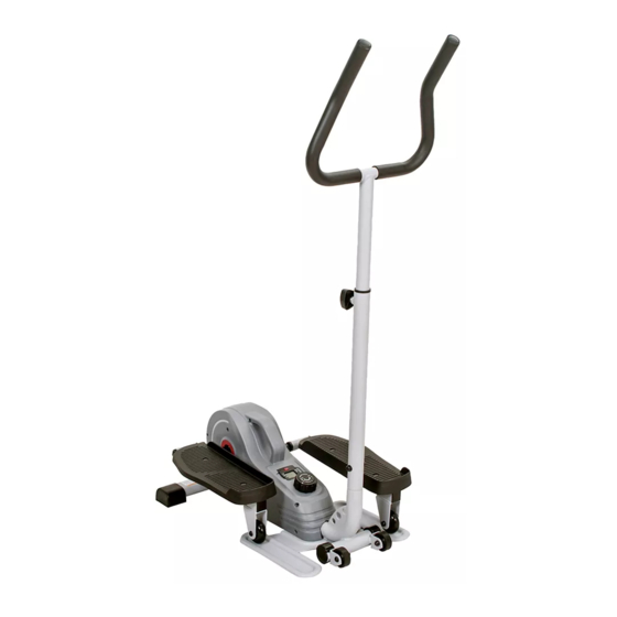
MAGNETIC STANDING ELLIPTICAL
WITH HANDLEBARS
SF-E3988
USER MANUAL
IMPORTANT! Please retain owner's manual for maintenance and adjustment instructions. Your
satisfaction is very important to us, PLEASE DO NOT RETURN UNTIL YOU HAVE CONTACTED
US: support@sunnyhealthfitness.com or 1- 877 - 90SUNNY (877-907-8669).
Advertisement
Table of Contents

Subscribe to Our Youtube Channel
Related Manuals for Sunny Health & Fitness SF-E3988


Summary of Contents for Sunny Health & Fitness SF-E3988
- Page 1 MAGNETIC STANDING ELLIPTICAL WITH HANDLEBARS SF-E3988 USER MANUAL IMPORTANT! Please retain owner’s manual for maintenance and adjustment instructions. Your satisfaction is very important to us, PLEASE DO NOT RETURN UNTIL YOU HAVE CONTACTED US: support@sunnyhealthfitness.com or 1- 877 - 90SUNNY (877-907-8669).
-
Page 2: Important Safety Information
IMPORTANT SAFETY INFORMATION We thank you for choosing our product. To ensure your safety and health, please use this equipment correctly. It is important to read this entire manual before assembling and using the equipment. Safe and effective use can only be achieved if the equipment is assembled, maintained, and used properly. It is your responsibility to ensure that all users of the equipment are informed of all warnings and precautions. -
Page 3: Exploded Diagram
EXPLODED DIAGRAM HARDWARE PACKAGE #67 S5 1PC... -
Page 4: Parts List
PARTS LIST Description Spec. Description Spec. Main Frame Screw M5*15 Φ8.2*Φ16*1.5 Pedal Frame (R) Flat Washer Pedal Frame (L) Sleeve Crank Bearing 6000 Φ10.2*Φ20*1.5 Magnetic Board Washer Idler Wheel Shaft Screw M10*20*12 Axle for Crank Nylon Nut 7L/R Pedal Spring 8L/R Belt Cover Wire Clip... - Page 5 ASSEMBLY INSTRUCTIONS We value your experience using Sunny Health and Fitness products. For assistance with parts or troubleshooting, please contact us at support@sunnyhealthfitness.com or 1-877-90SUNNY (877-907- 8669). STEP 1: Remove 3 Screws (No. 64) , 3 Washers (No. 66) and 3 Arc Washers (No. 65) from Main Frame (No.
-
Page 6: Exercise Computer
EXERCISE COMPUTER SPECIFICATIONS SPEED-----------------------------------------------0.0~999.9MPH (Mile/Hour) TIME ------------------------------------------------0:00~99:59MIN DISTANCE------------------------------------------0.0~9999M (Mile) CALORIES------------------------------------------0.0~9999KCAL FUNCTION KEYS: MODE: Press the red key repeatedly to select the desired value (Time, Speed, Distance, Calories, Scan). Hold the key for 4 seconds to have all function values reset (total reset). FUNCTIONS: SPEED: Displays current speed. - Page 7 ADJUSTMENTS & USAGE GUIDE ADJUSTING THE TENSION Adjust the tension by turning the Tension Control Knob (No. 9) clockwise to increase the level of resistance turning counter-clockwise decrease the level of resistance. Tension levels are set at Level 1 being the lowest and Level 8 being the highest.
-
Page 8: Battery Replacement
BATTERY REPLACEMENT PLASTIC CAP LR44 BATTERY SEAT BATTERY PLASTIC CAP WIRE INSERTING HOLE 1. Remove the Meter (No. 10) from Main Frame (No. 1). Then disconnect the link wire of Inductor (No. 49) from the Meter (No. 10). 2. Remove the plastic cap from the back of Meter (No. 10). 3.
Need help?
Do you have a question about the SF-E3988 and is the answer not in the manual?
Questions and answers