Table of Contents

Related Manuals for Cortalk RMU5 Generic

Summary of Contents for Cortalk RMU5 Generic
- Page 1 RMU5 Generic Installation and Configuration Guide Print Date: December 15, 2016 MOBILTEX® DATA LTD. TITLE: RMU5 Generic Installation and Configuration Guide Calgary, Alberta DOCUMENT NO.: SHEET: REV: RMU5-MAN-001 1 of 69 1.10...
-
Page 2: Revision History
IsatM2M satellite transceiver. 1.00 Jan 30, 2009 Original production release. Updated branding. Tony da Costa Formatting to match other corTalk documentation. New driver/app install 1.01 Apr 22, 2009 Tony da Costa procedure. Deleted RMU5-ISAT installation procedure, and added reference to RMU5-MAN-002 in its place. -
Page 3: Table Of Contents
Web Server ............................. 57 6.2.2 FTP Server .............................. 58 6.2.3 Telnet Server ............................58 6.2.4 RMUSetup .............................. 58 LCD Display ..............................58 MOBILTEX® DATA LTD. TITLE: RMU5 Generic Installation and Configuration Guide Calgary, Alberta DOCUMENT NO.: SHEET: REV: RMU5-MAN-001 3 of 69 1.10... - Page 4 Figure 48 TT-3026 Cable Termination ........................... 51 Figure 49 TT-3026 Cable Plugged Into DRI1 ........................ 51 Figure 50 Cobham Sailor 3027 Communicator and Cable ..................... 52 MOBILTEX® DATA LTD. TITLE: RMU5 Generic Installation and Configuration Guide Calgary, Alberta DOCUMENT NO.: SHEET: REV:...
- Page 5 Table 9 Ethernet 10/100 Connector ..........................64 Table 10 Default RMU5 I/O Point Modbus Addresses ....................66 Table 11 Register Behavior By I/O Point Type For Enabled Points ................67 MOBILTEX® DATA LTD. TITLE: RMU5 Generic Installation and Configuration Guide Calgary, Alberta DOCUMENT NO.: SHEET: REV:...
-
Page 6: Introduction
Additional modules added in the future as required ® This document details the installation and operation of the Mobiltex RMU5 remote monitoring unit product. MOBILTEX® DATA LTD. TITLE: RMU5 Generic Installation and Configuration Guide Calgary, Alberta DOCUMENT NO.: SHEET: REV: RMU5-MAN-001 6 of 69 1.10... -
Page 7: General Safety Information
Terminal including Amendment 1, or a later version of the Terminal same standard incorporating the same level of testing requirements. MOBILTEX® DATA LTD. TITLE: RMU5 Generic Installation and Configuration Guide Calgary, Alberta DOCUMENT NO.: SHEET: REV: RMU5-MAN-001 7 of 69... -
Page 8: Component Identification And Descriptions
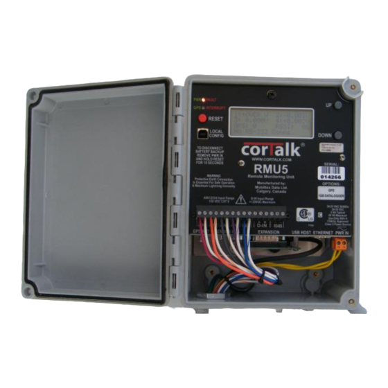
Figure 1 RMU5 Front/Side View MOBILTEX® DATA LTD. TITLE: RMU5 Generic Installation and Configuration Guide Calgary, Alberta DOCUMENT NO.: SHEET: REV:... -
Page 9: Figure 2 Rmu5 Back/Side View
GPS/Interrupter Status LED Indicator. This bi-color indicator shows status for the optional GPS Timing Control Module (TCM) board and also the rectifier interruption relay status. When green, the GPS TCM board MOBILTEX® DATA LTD. TITLE: RMU5 Generic Installation and Configuration Guide Calgary, Alberta DOCUMENT NO.: SHEET:... - Page 10 When drilling the holes for the feed-through connectors, avoid drilling into the RMU aluminum chassis. Any Interconnection wires used must be rated to 75°C or greater. MOBILTEX® DATA LTD. TITLE: RMU5 Generic Installation and Configuration Guide Calgary, Alberta DOCUMENT NO.: SHEET: REV:...
-
Page 11: Figure 3 Rmu5 Inside View
Figure 3 RMU5 Inside View MOBILTEX® DATA LTD. TITLE: RMU5 Generic Installation and Configuration Guide Calgary, Alberta DOCUMENT NO.: SHEET: REV: RMU5-MAN-001 11 of 69 1.10... -
Page 12: Installation
Installation of the cabling feed-through must be made in such a manner that does not degrade the environmental sealing characteristics of the RMU5. MOBILTEX® DATA LTD. TITLE: RMU5 Generic Installation and Configuration Guide Calgary, Alberta DOCUMENT NO.: SHEET:... -
Page 13: Wiring
RMU5. Consult the documentation provided by the transformer manufacturer to determine the correct primary tap wires required for a particular input voltage. MOBILTEX® DATA LTD. TITLE: RMU5 Generic Installation and Configuration Guide Calgary, Alberta DOCUMENT NO.: SHEET: REV:... -
Page 14: Gps Antenna
RMU5 at time of manufacturing. Included in the kit is a pre-terminated 10 meter (33’) RF cable and a GPS antenna. MOBILTEX® DATA LTD. TITLE: RMU5 Generic Installation and Configuration Guide Calgary, Alberta DOCUMENT NO.: SHEET:... -
Page 15: Measurement Wiring
These contacts may be attached to the DIN pins on the main I/O connector as shown in the typical installation diagram. Ensure that main rectifier power is off while performing any wiring on the RMU5. MOBILTEX® DATA LTD. TITLE: RMU5 Generic Installation and Configuration Guide Calgary, Alberta DOCUMENT NO.: SHEET: REV:... -
Page 16: Figure 8 Rmu5 Typical Rectifier Installation
Figure 8 RMU5 Typical Rectifier Installation MOBILTEX® DATA LTD. TITLE: RMU5 Generic Installation and Configuration Guide Calgary, Alberta DOCUMENT NO.: SHEET: REV: RMU5-MAN-001 16 of 69 1.10... -
Page 17: Interruption Relay Wiring
When using an alternate DC power source, such as thermo-electric generation or solar, only DC capable relays such as mechanical, mercury displacement, or DC solid state MOSFET can be used on the output to the protected structure. MOBILTEX® DATA LTD. TITLE: RMU5 Generic Installation and Configuration Guide Calgary, Alberta DOCUMENT NO.: SHEET:... -
Page 18: Figure 9 Mechanical And Mercury Displacement Relay Installation
Rectifier Transformer Rectifier Assembly Relay may be installed in any one of the two locations shown. Figure 10 AC Solid State Triac Relay Installation MOBILTEX® DATA LTD. TITLE: RMU5 Generic Installation and Configuration Guide Calgary, Alberta DOCUMENT NO.: SHEET: REV: RMU5-MAN-001 18 of 69 1.10... -
Page 19: Ac Solid State Relays
AC (for 120 & 230 volt rectifiers) or the secondary AC of the rectifier. K05232R5016 AC Relay - 3 phase, 48-530 VAC RMS 50 Amps max. 0-4A=No Heatsink, 4-30A=HE-90 MOBILTEX® DATA LTD. TITLE: RMU5 Generic Installation and Configuration Guide Calgary, Alberta DOCUMENT NO.: SHEET: REV: RMU5-MAN-001 19 of 69 1.10... -
Page 20: Ac Solid State Relay Heatsinks
4.2.5.2 AC Solid State Relay Heatsinks X030120HE54 Medium Heatsink for Solid State Relay - HE-54 Figure 14 X030120HE54 Medium Heatsink MOBILTEX® DATA LTD. TITLE: RMU5 Generic Installation and Configuration Guide Calgary, Alberta DOCUMENT NO.: SHEET: REV: RMU5-MAN-001 20 of 69... -
Page 21: Mercury Displacement Relays
Contact de-rating is shown in Table 2. When working with mercury relays, all locally applicable transport and disposal regulations must be followed. MOBILTEX® DATA LTD. TITLE: RMU5 Generic Installation and Configuration Guide Calgary, Alberta DOCUMENT NO.: SHEET:... -
Page 22: Door Switch Wiring
If a voltage source is used, the 12V source from the RMU5 is not connected to D-INA. MOBILTEX® DATA LTD. TITLE: RMU5 Generic Installation and Configuration Guide Calgary, Alberta DOCUMENT NO.: SHEET:... -
Page 23: Configuration
Click on the “Install RMU5 Configuration Applications” button to start the application installer. The following dialog may appear, click the “Run” button to continue: MOBILTEX® DATA LTD. TITLE: RMU5 Generic Installation and Configuration Guide Calgary, Alberta DOCUMENT NO.: SHEET: REV:... -
Page 24: Figure 19 Rmu5Configsetup.msi Security Warning Dialog
Figure 22. Click “Close” to complete the installation. When presented with the dialog shown in Figure 21, ensure that the “RMU5-corView and RMU5-Generic (Advanced Users)” radio button is selected! MOBILTEX® DATA LTD. TITLE: RMU5 Generic Installation and Configuration Guide Calgary, Alberta DOCUMENT NO.: SHEET: REV:... -
Page 25: Figure 21 Rmu5 Configuration Installation Option Selection
Figure 22 RMU5 Configuration Applications Installation Complete A shortcut to the configuration application and the RMU5 manual are created in the Windows start menu under the “RMU5 Configuration Application” folder. MOBILTEX® DATA LTD. TITLE: RMU5 Generic Installation and Configuration Guide Calgary, Alberta DOCUMENT NO.: SHEET: REV:... -
Page 26: Usb Driver
To complete installing the driver, ensure that the RMU5 is powered, then attach a USB A-B cable between the USB host port on the PC and the USB slave port on the RMU5 (labeled “Local Config”). The following dialog may appear on the MOBILTEX® DATA LTD. TITLE: RMU5 Generic Installation and Configuration Guide Calgary, Alberta DOCUMENT NO.: SHEET:... -
Page 27: Figure 26 Windows Xp Found New Hardware Dialog #1
Figure 27 Windows XP Found New Hardware Dialog #2 The following dialog may then appear depending on the code signing settings for the PC: MOBILTEX® DATA LTD. TITLE: RMU5 Generic Installation and Configuration Guide Calgary, Alberta DOCUMENT NO.: SHEET: REV:... -
Page 28: Figure 28 Windows Xp Found New Hardware Dialog #3
Network Connections applet in the Windows XP control panel. The device name will be “RMU5 Configuration Remote NDIS”, and may be followed by a number. MOBILTEX® DATA LTD. TITLE: RMU5 Generic Installation and Configuration Guide Calgary, Alberta DOCUMENT NO.: SHEET:... -
Page 29: Rmusetup Application
“Connect”. The following dialog will appear: Figure 31 Connect Password Dialog Enter the RMUSetup default username of “admin” and the default password of “admin” and click on “OK”. MOBILTEX® DATA LTD. TITLE: RMU5 Generic Installation and Configuration Guide Calgary, Alberta DOCUMENT NO.: SHEET: REV:... -
Page 30: Rmu Configuration
“Install Defaults” button for a default configuration. If the RMU5 has already been configured and some changes are required to the configuration, read the configuration back from the RMU5 using the “Read From RMU” button. MOBILTEX® DATA LTD. TITLE: RMU5 Generic Installation and Configuration Guide Calgary, Alberta DOCUMENT NO.: SHEET: REV:... - Page 31 “System Control” group. Copies of the configuration may also be stored locally on the PC by clicking the “Write To Disk” button. MOBILTEX® DATA LTD. TITLE: RMU5 Generic Installation and Configuration Guide Calgary, Alberta DOCUMENT NO.: SHEET:...
-
Page 32: System Configuration Properties
Data Log Size. This field is used to limit the maximum size of individual data log files on the RMU5. Once a data log file exceeds this size, it is closed and a new file is started. MOBILTEX® DATA LTD. TITLE: RMU5 Generic Installation and Configuration Guide Calgary, Alberta DOCUMENT NO.: SHEET:... - Page 33 The check boxes in this group can be used to limit the days of the week when reports will be sent. . Note that this setting is not applicable to Skywave IsatM2M and MODBUS communications modes. MOBILTEX® DATA LTD. TITLE: RMU5 Generic Installation and Configuration Guide Calgary, Alberta DOCUMENT NO.: SHEET: REV:...
-
Page 34: Ethernet Configuration Properties
Ethernet port also supports an FTP server and Telnet server that are always enabled. Access to these features requires authentication based on the parameters in the “Accounts” settings tab. MOBILTEX® DATA LTD. TITLE: RMU5 Generic Installation and Configuration Guide Calgary, Alberta DOCUMENT NO.: SHEET:... -
Page 35: Rs-232 Port Properties
Function of this Port. The RS-232 port on the communications expansion port may be used for one of several purposes. The radio buttons in this grouping allow selection of the device type that is attached to the RS-232 port. MOBILTEX® DATA LTD. TITLE: RMU5 Generic Installation and Configuration Guide Calgary, Alberta DOCUMENT NO.: SHEET:... -
Page 36: Instrumentation Port (Sensor Bus) Properties
The “RS-485/MODBUS Port” properties page is used to configure the serial MODBUS slave that can be accessed via the RS-485 port on the main I/O connector. MOBILTEX® DATA LTD. TITLE: RMU5 Generic Installation and Configuration Guide Calgary, Alberta DOCUMENT NO.: SHEET:... -
Page 37: Figure 37 Rmu5 Configuration - Rs-485/Modbus Port Properties
Communications. The RS-232 UART communications properties are set in this group. The default button, when clicked, will set the parameters to nominal values used with the MODBUS protocol. MODBUS Address. This parameter sets the MODBUS slave address. MOBILTEX® DATA LTD. TITLE: RMU5 Generic Installation and Configuration Guide Calgary, Alberta DOCUMENT NO.: SHEET: REV:... -
Page 38: Bluetooth Port Properties
Security PIN. This parameter allows setting the PIN code associated with Bluetooth pairing. Refer to your PDA or laptop manual for the exact pairing procedure for the host device. MOBILTEX® DATA LTD. TITLE: RMU5 Generic Installation and Configuration Guide Calgary, Alberta DOCUMENT NO.: SHEET:... -
Page 39: Interrupter Properties
UTC time mark. This parameter may be set between 0 and 5000ms. Use of this parameter only applies to units equipped with the GPS timing control module board. MOBILTEX® DATA LTD. TITLE: RMU5 Generic Installation and Configuration Guide Calgary, Alberta DOCUMENT NO.: SHEET:... - Page 40 13. Schedules On Time. The RMU5 may be programmed with a specific date and time and the interruption output will operate in a cycling mode for the specified duration. This date and time may be enabled by selecting the enable check box. MOBILTEX® DATA LTD. TITLE: RMU5 Generic Installation and Configuration Guide Calgary, Alberta DOCUMENT NO.: SHEET: REV:...
-
Page 41: Accounts Parameters
The “I/O Points” parameter page contains settings related to each I/O point in the system. The RMU5 has 13 built in I/O points, and is expandable to 50 I/O points using external modules attached to the sensor expansion bus. MOBILTEX® DATA LTD. TITLE: RMU5 Generic Installation and Configuration Guide Calgary, Alberta DOCUMENT NO.: SHEET:... -
Page 42: Figure 41 Rmu5 Configuration - I/O Points Properties
Checking the Enable checkbox enables a report to be sent when the channel enters the alarm state. Checking the Report on Return to MOBILTEX® DATA LTD. TITLE: RMU5 Generic Installation and Configuration Guide Calgary, Alberta DOCUMENT NO.: SHEET:... - Page 43 For one of the four RMU5 internal analog inputs, set the range selection by pressing the button next to “Select Range” in the “Analog Input Calibration” group until an appropriate range is selected for the measurement MOBILTEX® DATA LTD. TITLE: RMU5 Generic Installation and Configuration Guide Calgary, Alberta DOCUMENT NO.: SHEET:...
- Page 44 Note: When communicating measurements over the Easytrack satellite communicator, it is possible to indicate to the back-end host that a channel is disabled by setting the channel scaling field to a value of 0. MOBILTEX® DATA LTD. TITLE: RMU5 Generic Installation and Configuration Guide Calgary, Alberta DOCUMENT NO.: SHEET:...
-
Page 45: System Control
Timing Control Module board. Position, time, and lock status, and satellite status are shown. Finally, the version of the RMU5 application can be retrieved by pressing the “Read Version” button. MOBILTEX® DATA LTD. TITLE: RMU5 Generic Installation and Configuration Guide Calgary, Alberta DOCUMENT NO.: SHEET:... -
Page 46: Rectifier/Interrupter
RMU5 will be cleared after the files are retrieved. Clicking either button brings up a file dialog to locate where the files will be placed after retrieval from the RMU5. MOBILTEX® DATA LTD. TITLE: RMU5 Generic Installation and Configuration Guide Calgary, Alberta DOCUMENT NO.: SHEET:... -
Page 47: Operation
The RMU5 is capable of sending data to a custom host over the Iridium satellite system using an RMU3-S Iridium satellite modem. The data is sent in a proprietary format which is decodable by the Mobiltex Cathodic Monitoring Host MOBILTEX® DATA LTD. TITLE: RMU5 Generic Installation and Configuration Guide Calgary, Alberta DOCUMENT NO.: SHEET:... -
Page 48: Skywave Isatm2M Satellite
RMU5 is equipped with a Skywave IDP-680 satellite transceiver (see Figure 43). The RMU5 must also be fitted with a DRI1-SKYSAT interface board. MOBILTEX® DATA LTD. TITLE: RMU5 Generic Installation and Configuration Guide Calgary, Alberta DOCUMENT NO.: SHEET:... -
Page 49: Cellular Gsm Sms
For further information on configuring an RMU5 for use with the cellular transceiver, refer to Mobiltex document RMU5-MAN-002, entitled “RMU5-corView Installation and Configuration Guide”. MOBILTEX® DATA LTD. TITLE: RMU5 Generic Installation and Configuration Guide Calgary, Alberta DOCUMENT NO.: SHEET: REV:... -
Page 50: Inmarsat C (Easytrack/Sailor) Satellite
For installation of the TT-3026 transceiver, refer to the Thrane&Thrane TT-36026L/M/S easyTrack Transceiver Installation Manual, which is included with the transceiver. 6.1.10.1.2 Wiring MOBILTEX® DATA LTD. TITLE: RMU5 Generic Installation and Configuration Guide Calgary, Alberta DOCUMENT NO.: SHEET: REV: RMU5-MAN-001 50 of 69 1.10... -
Page 51: Figure 48 Tt-3026 Cable Termination
DRI1 Easytrack Sat Interface Board (see Figure 49). Figure 48 TT-3026 Cable Termination Figure 49 TT-3026 Cable Plugged Into DRI1 MOBILTEX® DATA LTD. TITLE: RMU5 Generic Installation and Configuration Guide Calgary, Alberta DOCUMENT NO.: SHEET: REV: RMU5-MAN-001 51 of 69 1.10... -
Page 52: Sailor 3027 Antenna
Figure 51 Sailor 3027 Adjustable Pole/Railing Mount Kit For installation of the Sailor 3027 transceiver, refer to the Cobham/Thrane&Thrane Sailor 6120/30/40/50 System Installation Manual, which is included with the transceiver. MOBILTEX® DATA LTD. TITLE: RMU5 Generic Installation and Configuration Guide Calgary, Alberta DOCUMENT NO.: SHEET: REV:... -
Page 53: Figure 52 Sailor 3027 Cable Termination
DRI3 Sailor 3027 Sat Interface Board (see Figure 53). Figure 52 Sailor 3027 Cable Termination Figure 53 Sailor 3027 Cable Plugged Into DRI3 MOBILTEX® DATA LTD. TITLE: RMU5 Generic Installation and Configuration Guide Calgary, Alberta DOCUMENT NO.: SHEET: REV:... -
Page 54: Satellite Service
The “Status” button in the RMU5Setup Radio Communications grouping can be used to determine the status of the satellite transceiver connection to the satellite. Click this button to bring up the following dialog. MOBILTEX® DATA LTD. TITLE: RMU5 Generic Installation and Configuration Guide Calgary, Alberta DOCUMENT NO.: SHEET:... -
Page 55: Figure 55 Easytrack Communications Status
This test transmission should only be used if there are communications issues suspected some time (i.e. days) after installation has occurred. MOBILTEX® DATA LTD. TITLE: RMU5 Generic Installation and Configuration Guide Calgary, Alberta DOCUMENT NO.: SHEET:... - Page 56 Current Member The current LES/DNID/Member are shown in the DNID table area. The entry with the asterisk next to it signifies the currently selected information. MOBILTEX® DATA LTD. TITLE: RMU5 Generic Installation and Configuration Guide Calgary, Alberta DOCUMENT NO.: SHEET: REV:...
-
Page 57: Ethernet Services
The username and password can be anyone of the three system accounts defined in the RMUSetup configuration. Figure 56 RMU5 Web Server Page MOBILTEX® DATA LTD. TITLE: RMU5 Generic Installation and Configuration Guide Calgary, Alberta DOCUMENT NO.: SHEET: REV:... -
Page 58: Ftp Server
An additional number of readings pages may also be present if an analog channel expansion unit is attached to the RMU5 sensor bus. Base RMU I/O CH1 DC MOBILTEX® DATA LTD. TITLE: RMU5 Generic Installation and Configuration Guide Calgary, Alberta DOCUMENT NO.: SHEET: REV: RMU5-MAN-001 58 of 69 1.10... -
Page 59: System Shutdown
Disconnect the orange 24VAC/DC main power connector from the RMU5. Press and hold the RESET button for 10-15s, until the green PWR LED turns off. MOBILTEX® DATA LTD. TITLE: RMU5 Generic Installation and Configuration Guide Calgary, Alberta DOCUMENT NO.: SHEET:... -
Page 60: Servicing
The RMU5 contains no user serviceable components. In case of failure, return the complete unit to Mobiltex for servicing. The internal sealed-lead acid backup battery should only be replaced by Mobiltex. No cleaning is required. MOBILTEX® DATA LTD. TITLE: RMU5 Generic Installation and Configuration Guide Calgary, Alberta DOCUMENT NO.: SHEET: REV: RMU5-MAN-001 60 of 69 1.10... -
Page 61: User Accessible Connector Pin Outs
Power/Signal Ground RS485+ RS485 MODBUS Port Positive Connection RS485- RS485 MODBUS Port Negative Connection Table 3 Main I/O Connector Pinout MOBILTEX® DATA LTD. TITLE: RMU5 Generic Installation and Configuration Guide Calgary, Alberta DOCUMENT NO.: SHEET: REV: RMU5-MAN-001 61 of 69 1.10... -
Page 62: Table 4 Communications Expansion Connector Pinout
(Shared With Main I/O RS-485 Connections) +5V Supply For Communication Peripheral (2A COMM+5V max) I2C Bus Clock Line Table 4 Communications Expansion Connector Pinout MOBILTEX® DATA LTD. TITLE: RMU5 Generic Installation and Configuration Guide Calgary, Alberta DOCUMENT NO.: SHEET: REV: RMU5-MAN-001 62 of 69 1.10... -
Page 63: Table 5 Instrumentation Sensor Expansion Bus Connector
USB +5V Power (500mA max) USB Data Negative Signal USB Data Positive Signal Signal/Power Ground Table 7 USB Host Connector MOBILTEX® DATA LTD. TITLE: RMU5 Generic Installation and Configuration Guide Calgary, Alberta DOCUMENT NO.: SHEET: REV: RMU5-MAN-001 63 of 69... -
Page 64: Table 8 Usb Slave Configuration Connector
Tied directly to pin 7, both pins pass TERM2B through 75ohm resistor to chassis ground through 1nF capacitor. Table 9 Ethernet 10/100 Connector MOBILTEX® DATA LTD. TITLE: RMU5 Generic Installation and Configuration Guide Calgary, Alberta DOCUMENT NO.: SHEET: REV: RMU5-MAN-001 64 of 69... -
Page 65: Modbus Register Reference
Similarly, a write to the block writes into a temporary variable block until the Second register is written. At that point the real time clock is updated with the values from the temporary variable block. MOBILTEX® DATA LTD. TITLE: RMU5 Generic Installation and Configuration Guide Calgary, Alberta DOCUMENT NO.: SHEET: REV:... -
Page 66: Table 10 Default Rmu5 I/O Point Modbus Addresses
Table 10 Default RMU5 I/O Point Modbus Addresses MOBILTEX® DATA LTD. TITLE: RMU5 Generic Installation and Configuration Guide Calgary, Alberta DOCUMENT NO.: SHEET: REV:... -
Page 67: Table 11 Register Behavior By I/O Point Type For Enabled Points
Error code returned table above Table 11 Register Behavior By I/O Point Type For Enabled Points Disabled points return an error code on any access. MOBILTEX® DATA LTD. TITLE: RMU5 Generic Installation and Configuration Guide Calgary, Alberta DOCUMENT NO.: SHEET: REV: RMU5-MAN-001 67 of 69 1.10... -
Page 68: Specifications
Measurement types: AC RMS and DC, simultaneous per channel Input Impedance: 20MOhm minimum Resolution: 16-bit Maximum sampling rate: 20 sps MOBILTEX® DATA LTD. TITLE: RMU5 Generic Installation and Configuration Guide Calgary, Alberta DOCUMENT NO.: SHEET: REV: RMU5-MAN-001 68 of 69 1.10... -
Page 69: Rmu5-Man-001
Technical assistance may be obtained from: Mobiltex Data Ltd. 3640-26 Street NE Calgary, AB T1Y 4T7 Canada Tel: (403)291-2770 Web: http://www.mobiltex.com MOBILTEX® DATA LTD. TITLE: RMU5 Generic Installation and Configuration Guide Calgary, Alberta DOCUMENT NO.: SHEET: REV: RMU5-MAN-001 69 of 69 1.10...
Need help?
Do you have a question about the RMU5 Generic and is the answer not in the manual?
Questions and answers